
|
This work is licensed under a
Creative Commons Attribution-Noncommercial-Share Alike 3.0 License. |
 |
Westbury Whippet ProjectClick on a photo to view it larger size. |
 Introduction
Kit and Disclaimer
Plans and Error Corrections
Equipment Required
Crankcase
Camshaft and Gearcase
Nose Piece and Fixup
Conrod
Crankshaft and Flywheel
Piston and Cylinder Liner
Cylinder Head
Carburettor
Valves
Ignition Timer(s)
Fettlin' and Fiddlin'
Introduction
Kit and Disclaimer
Plans and Error Corrections
Equipment Required
Crankcase
Camshaft and Gearcase
Nose Piece and Fixup
Conrod
Crankshaft and Flywheel
Piston and Cylinder Liner
Cylinder Head
Carburettor
Valves
Ignition Timer(s)
Fettlin' and Fiddlin'
Introduction

Looking at the engines designed by Edgar T Westbury (ETW), the word that leaps to my mind is "practical". With the possible exception of the Ladybird, the word "attractive" does not intrude! That said, the practicality of his designs does have a certain attractiveness that has nothing to do with appearence. Close examination of his designs shows that he not only considered how the engine would operate, but how the engine could be constructed in a modestly equipped home machine shop. And if there is an occasional lapse in this aspect, such as the infamous intersecting studs of the Seal, put it down to the volume and variery of his IC and steam engine designs.
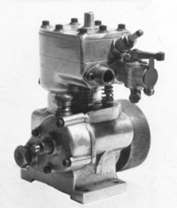 The Whippet is a classic case of an engine that conveys an air of having been well thought out to meet its design objectives, unhindered by any pretension towards style. Perhaps the best way to introduce this engine is to quote from the first part of the construction series text that appeared in the Model Engineer of June 1, 1963. In this, ETW related how the design came about as a result of many discussions with and requests from ME readers:
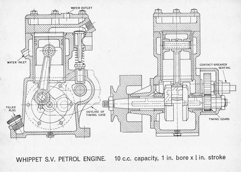
The design selected to meet these requirements is a single cylinder, four-cycle, spark ignition, side-valve, plain bearing, petrol engine of 0.59 cuin displacement. It features a wet sump with "splash" lubrication that can be cooled by a syphon system—no oil or water pumps are required. The crankshaft is a simple over-hung design with a follower that engages the crankpin to drive the timing gears. The permits the use of a simple conrod with solid ends, further simplifying construction and assembly. The cam drive employs an idler gear allowing the required spacing from crankshaft to camshaft to be achieved without the need for an overly large driven gear on the camshaft. This also simplifies crankcase boring operations as the location of the crank and camshaft bore locations are not critical; correct mesh being attained by the subsequent placement of the idler pinion.
ETW admits that the choice of the side valve arrangement restricts the compression ratio and is not generally conducive to high performance. However it does reduce both the component count, completity, and the overall height while facilitating effective water cooling of the head. It also provides flexible and quiet operation. Although the "mono-block" crankcase may at first appear bulky and complex, it actually simplifies construction and provides a very practical mounting base for an engine intended for marine operation. If we consider all the design and construction features, combined with a size that requires no parts akin to "watch-making", we have an engine that can be tackled with confidence by a model engineer having only moderate prior experience in IC or steam engine construction who is prepared to work accurately and methodically.
The Kit and The Disclaimer
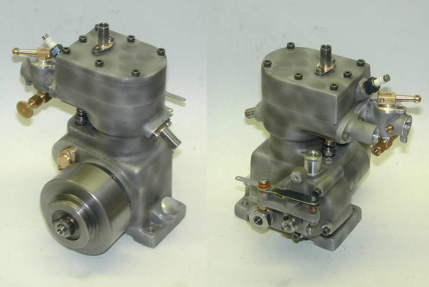
I suppose the crankcase could be hogged from a solid lump, or fabricated. However that is not necessary as Hemingway Kits (England) can supply the castings, or a complete materials kit for this and several other ETW designs. I'm sitting here staring at two of these materials kits, which is why I feel the sudden urge to disclaim. Mention of the kit availability in Model Engine News prompted Kirk Burwell of Hemingway Kits to make an offer I could not refuse: he'd Fedex me two kits; one would be mine and the other would be completed and returned to him so he could display and run it on his stand at UK trade and model engineering shows. Generous graft like this deserves special consideration, but I like to retain some pretense to fearless independence, so I'll call it like I see it in regards to kit quality, but any findings will be fed back to Kirk for attention, allowing me to shamelessly praise and promote Hemingway for all positive responses .
.
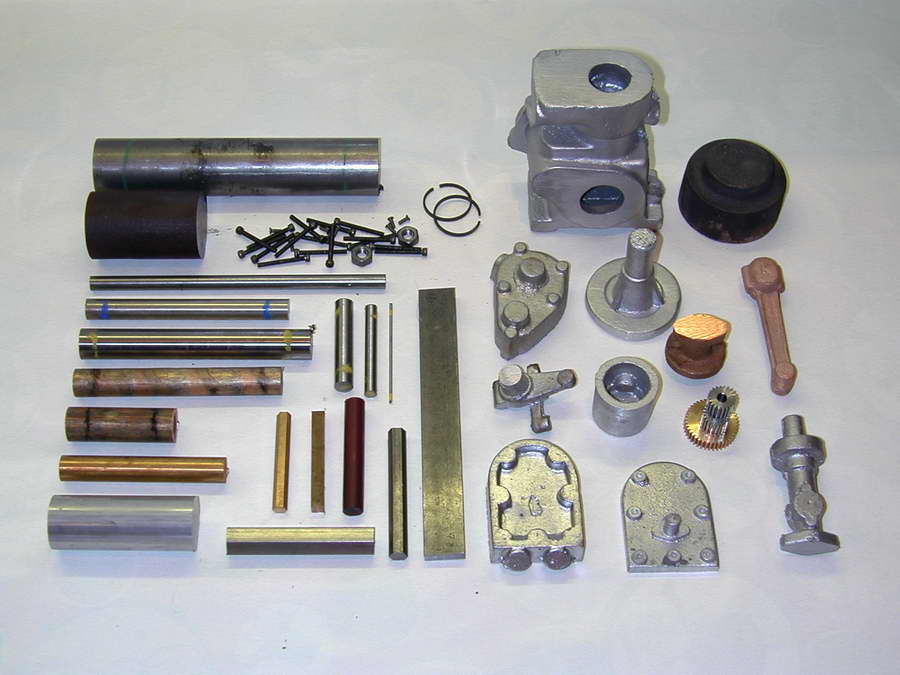
The first step taken by the meticulous kit builder is to inventory the parts and identify the purpose of each. The rest of us do it as we go, then find we've used the wrong item for some part and must now invent some plausable story to make the supplier believe it's their fault and so send a replacement. The materials kit, as received and unpacked, is shown below. It comprises aluminium, gun metal and iron castings, round, hex, and flat stock in the appropriate sizes, to the required meterial specification, and a hardware pack. Special material grades are color coded with a standard Hemingway chart providing identification. The color coding pigment is easily rubbed off, so avoid excessive handling until you are ready to machine the material. Table 1 (below) gives my best guess as to the purpose of the kit parts. The amount supplied seems adequate in all cases except a couple which are generously excessive.
 |
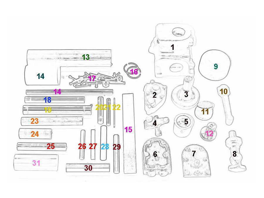 |
| 1 | aluminium sand casting | Crankcase |
| 2 | aluminium sand casting | Gearcase Cover |
| 3 | aluminium sand casting | Front Bearing Housing |
| 4 | aluminium sand casting | Ignition Timer Frame |
| 5 | aluminium sand casting | Piston |
| 6 | aluminium sand casting | Cylinder Head |
| 7 | aluminium sand casting | Cylinder Head Cover |
| 8 | aluminium sand casting | Carburettor |
| 9 | iron sand casting | Flywheel |
| 10 | gun-metal sand casting | Conrod (for Kiwi?) |
| 11 | gun-metal sand casting | Camshaft Bearings |
| 12 | steel and brass | Timing Gears (3) |
| 13 | 1-1/4" high-tensile steel rod | Crankshafts |
| 14 | 35.5mm cast iron rod | Cylinder Liner |
| 14 | 5/16" mild steel rod | Tappets |
| 15 | steel flat | Cam Jig |
| 16 | cast iron | Finished Piston Rings (2) |
| 17 | various | Hardware Pack |
| 18 | 5/16" stainless steel rod | Valves |
| 19 | 5/8" drill rod | Camshaft |
| 20 | 3/8" drill rod | unknown! |
| 21 | 1/4" drill rod | wrist pin and idler pivot |
| 22 | 1/16" drill rod | Needle Valve |
| 23 | .56" leaded phosphor bronze rod | Valve Cage (2) and Camshaft Bushing |
| 24 | .67" leaded phosphor bronze rod | Crankshaft Bushings (3) |
| 25 | 1/2" brass rod | Carburettor Bits, various |
| 26 | 1/4" AF hex brass | Valve Lock-nuts and fuel pipe nuts |
| 27 | 1/4" square brass | Throttle Arm and Carburettor Jet |
| 28 | phenolic rod | Timer Insulators |
| 29 | 5/16" AF hex steel rod | Upper Valve Nuts |
| 30 | 1/2" AF hex steel rod | Gear Retainer Nuts |
| 31 | 1" alloy bar | Anybody's Guess! |
Table 1 - Bill of Materials
The hardware pack includes BA screws, BSF nuts, pre-cut gears, and—most unusual, but most welcome—finished, gapped, piston rings. Although thicker than those made to the Trimble Method, they show no scale indicating that they have been annealed at a temperature below the critical point for cast-iron. This results in a stronger ring than that produced by those of us not blessed with a temperature controlled furnace who must heat to red heat and hope for the best. Valve springs are included too, but were not quite ready when my kits shipped, so they will come later. Kirk has also asked that I document all the fasteners used so he can ensure the kits are absolutely complete to the last nut and bolt.
Explicitly excluded from the kit are materials for the contact breaker points. The plans show a very traditional ETW-style contact breaker assembly with a tungsten tipped 6BA adjusting screw and tungsten tipped rivet. Hemingway can be excused for this exclusion as these are the proverbial rocking-horse droppings these days. Fortunately there are modern alternatives and work-arounds to this problem which I'll discuss when we get to that part of construction. But on the whole, the kit is quite complete with acceptable quality work on the castings.
Plans and instructions are not included as many builders will already have the three Model Engineer issues that detail the design. Specifically, these are Volume 129, Issues 3226, 7, and 8. Note that the last part ends with *To be continued, but as far as is known, it never was! To add to the confusion, the second part ends with a hanging "The" before the TBC line. As the third part does not start with a "The", this suggests either lost text, or sloppy editing. If you don't have them, a photocopy can be ordered from Hemingway, separate to the kit.
The first installment in the ME included an eight page "fold-out" set of plans for the major components with most drawn to twice scale. The magazine had changed from a small size to a much larger one commencing with issue 3224 and introduced the fold-out plan with that issue as part of the new image, the first such plan being the ETW Wyvern OHV, horizontal farm engine. The idea died out after just one more attempt (a live steam loco 3-view), but apparently as a side effect of this format, neither the Wyvern nor the Whippet ever appeared as orderable, complete plans in the ME plans list.
Plans and Error Corrections
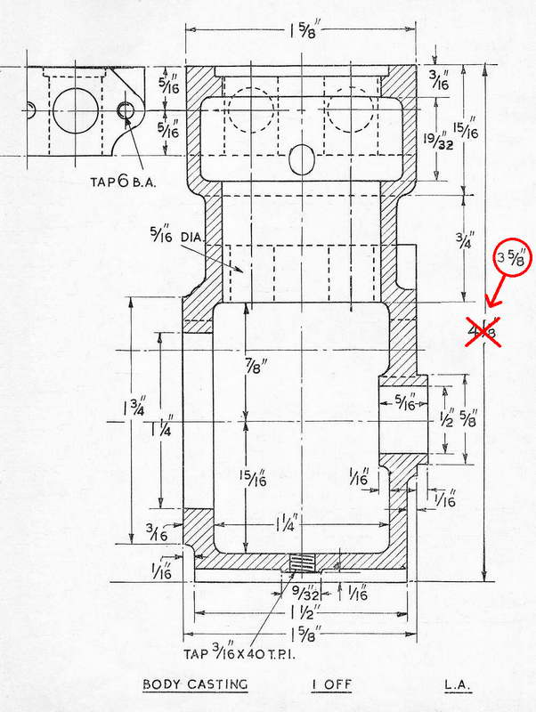
The plan pack option from Hemingway provides a copy of all the series text, plus a nicely composed plan that neatly assembles all the drawings from all the articles onto a single large sheet in 1:1 scale, except for the cylinder liner and flywheel which are in half-scale (they were printed full size on the original twice scale drawings—guess what happened). Close examination of the Hemingway sheet indicated two cases where the dimensioning style indicated that a change had been made. Cross-checking against the original Model Engineer drawings confirmed that the changes were, in fact, error corrections. The first is an incorrect overall height for the machined casting.
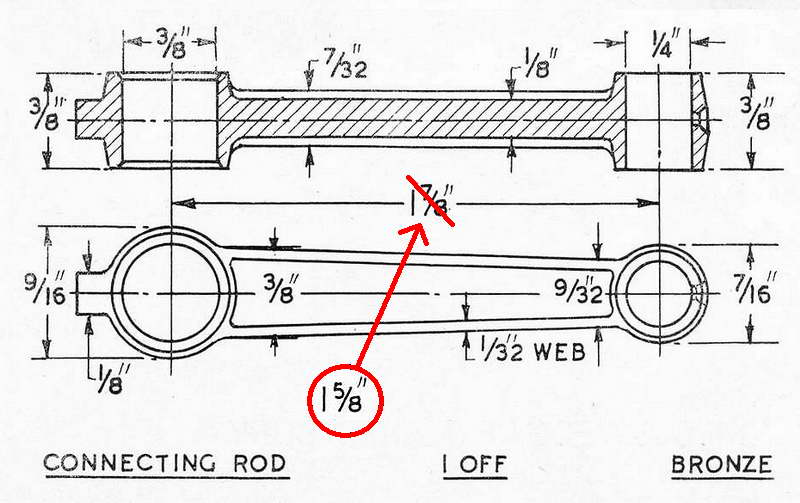 The other is the between centers distance for the conrod that if followed, would ensure that the engine would not actually turn over with the head on! The correct height from machined base to machined cylinder head mounting face should be 3-5/8", not 4-1/4" as shown originally. The correct between centers distance for the conrod is 1-5/8", not 1-3/4".
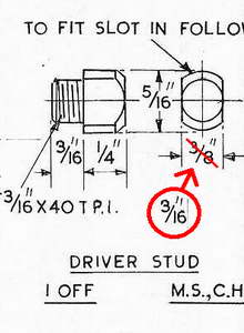
Later on, I discovered another error, uncorrected on the Woking/Hemingway print as received. The slot in the crankshaft follower for the drive pin is 3/16" wide. The pin is dimensioned as being 3/8" wide and is obviously not going to fit in the slot! The part is correctly proportioned though, so it is just a slip of the pen—easy to do in the days before CAD.
 Then there's this one—the distance marked for the middle head bolts relative to the outer ones on the head and head cover disagree by 1/16". This composite shows the problem and the dimension that I believe is the correct one. Sadly, the cast-in bosses on the head have deep drill center dimples which have the incorrect spacing, so if you drill using the correct 7/8" spacing, the holes will appear to be badly off center in the bosses. The water passage holes ("Z") are poorly positioned too. They may nestle neatly either side of the bolt bosses in the drawing, but the size of these bosses as cast is much larger, so they intersect badly. And the one to the left of the bolt hole we were just discussing goes nowhere near the water jacket, making it rather useless. See the page describing the head components for more information on this mess.
Equipment Required
All you really need is a lathe. It will need a swing of at least 3-1/2" (English measure from bed to center line, so in the USA, this would be called a 7" lathe). You will also require three and four jaw chucks and a faceplate with a decent angle plate for machining the crankcase. Any of the Myford 7 series of machines is adequate and doubtless the lathe ETW had in mind as the minimum equipment spectification for the design.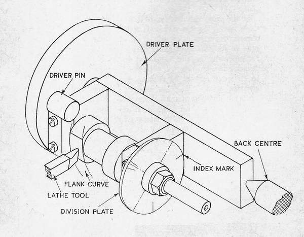 The plans show a jig for machining the cam flanks on the lathe and material for this jig is included with the Hemingway kit. An alternate approach, if you have a mill, is to use a table of tangential lift figures produced by CamCalc. Regardless of the method you use, the cams will require some hand filing and polishing. The ETW jig produces smooth flanks, but you must hand file the nose radius and smooth the base circle. In contrast, the CamCalc cam will have a close to perfect nose radius, a slightly faceted flank radius, and a similar base circle contour. Which you choose comes down to the equipment you have in your shop. If all you have is a lathe, the ETW method is a good solution. If you have a mill and a rotary table, the lift table approach requires less effort (no jig to fabricate) and produces a better job with an accurate nose radius.
The table below shows the input data required by CamCalc with buttons that automatically enter the data for you, then call the PHP version of the program to generate values with 5° spacing. The generated data includes the minimum tappet diameter required to assure tangential contact with the cam at all times. The diameter given for the Whippet tappets is adequate for the exhaust, but slightly too small to maintain tangential contact at all times for the inlet. This will result in a little "slap" as the exhaust opens and closes that is not really worth correcting on a relitively low revving model engine.
| Whippet | Inlet | Exhaust |
| Cam angle (°) | 120 | 130 |
| Lift (inches) | 0.094 | 0.094 |
| Flank radius (inches) | 1.0 | 1.0 |
| Base circle radius (inches) | 0.219 | 0.219 |
(Engine max RPM 6000; increments whatever you like)
ETW's suggestions for machining the parts are, as usual, terse, but he provides valuable insights into why some part was designed the way it was, and how best to hold it for machining. In common to many of his articles, the text contains his somewhat frustrating tendancy to skip lightly over some small detail, such as how to machine the valves, saying he has described it before so many times that it is not worth repeating! I have sympathy for his view, but I also have hyperlinks, so hopefully these pages will fill in the gaps.

Please submit all questions and comments to [email protected]