 |
Westbury Whippet Project:
|
Whippet's timer is a simple, open design that uses a leaf-spring contact that is insulated from the timer body. This is actuated by an insulated push rod bearing against a steel cam which is attached semi-permanently to the end of the camshaft by a taper pin. The timer frame is lightly clamped to the rear camshaft bush that protrudes from the timing gear cover. By adjusting the clamping bolt, sufficient friction is obtained to hold it in position, while allowing advance and retard movement through pressure on the vertical arm cast into the frame. This design, with minor variations, was used by ETW on many of his designs. It was simple and effective in its day, but now suffers from one major drawback: the tungsten tipped points specified are nearly impossible to obtain! I'm lucky to have stockpiled a small supply of these a long time ago, but that is no help to others, so this page will first detail the traditional "per the plans" timer, with tungsten tipped points, then look at replacing this with a thoroughly modern Hall-effect alternative.

Traditional Ignition Timer
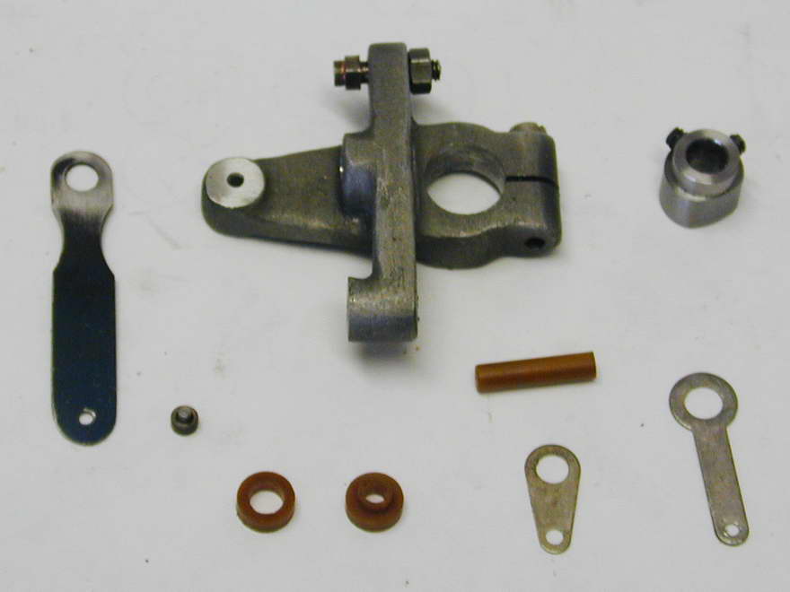
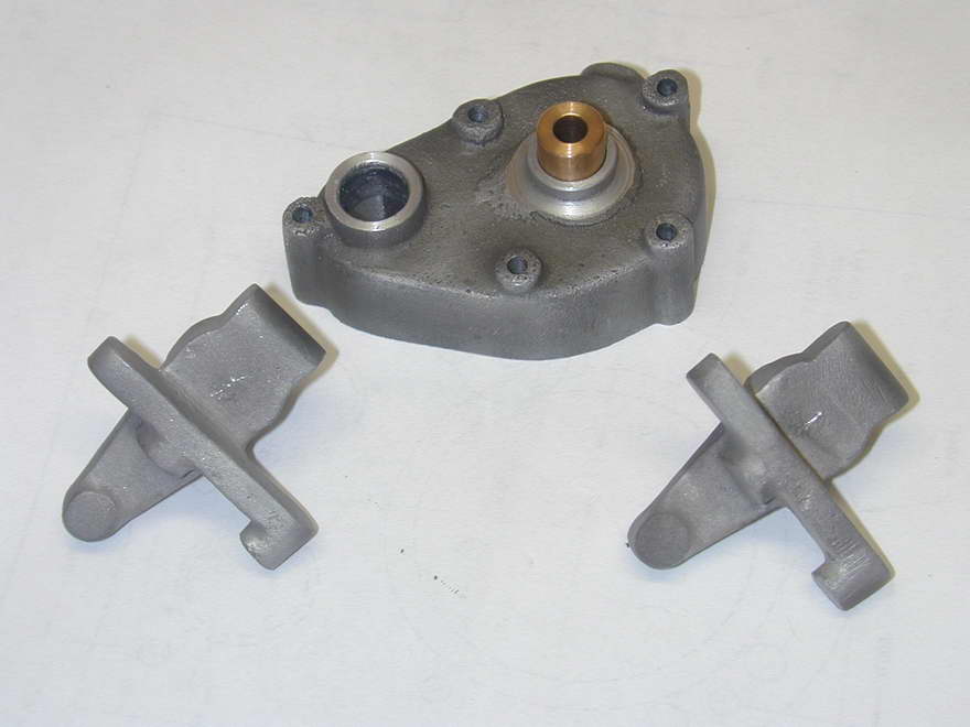 This shot shows the timer casting, marked out, ready for machining, with the gear case cover and cam shaft bush the timer will attach to. The timer castings have been fettled and blasted as described in Page 8 of this series, then marked out for boring. Forget the location of the cast spiggot on the frame (as usual). Measure down from the underside of the horizontal arm, then center-pop equidistant from the sides of the frame in the clamp area.
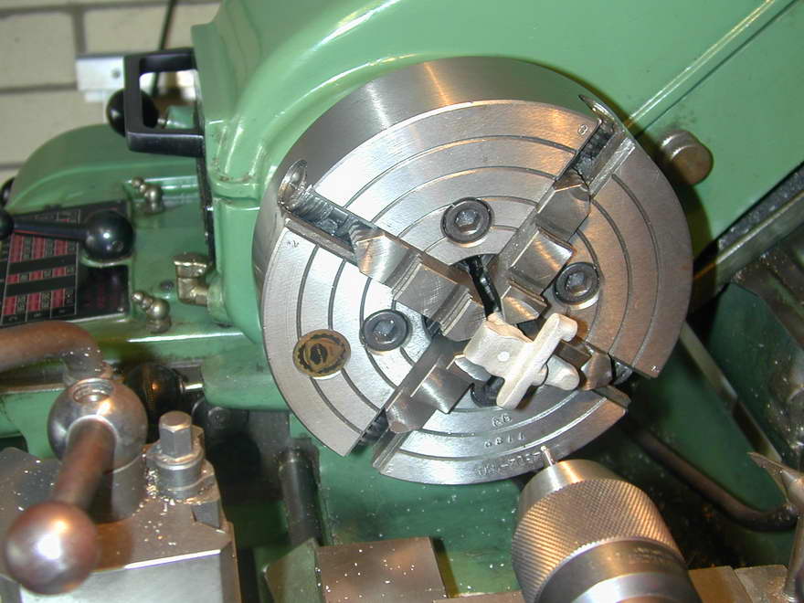 Chuck the casting in the 4-jaw chuck and set the center-pop to run true, bumping the casting around so the cross-arm of the frame that will mount the spring is at right angles to the lathe axis. Drill through, then bore out to a close sliding fit on the cam shaft bearing (it helps not to have glued or pressed this into the gear case cover just yet). Experience has shown me time and again that things always close up when slit, so don't make the fit too tight.
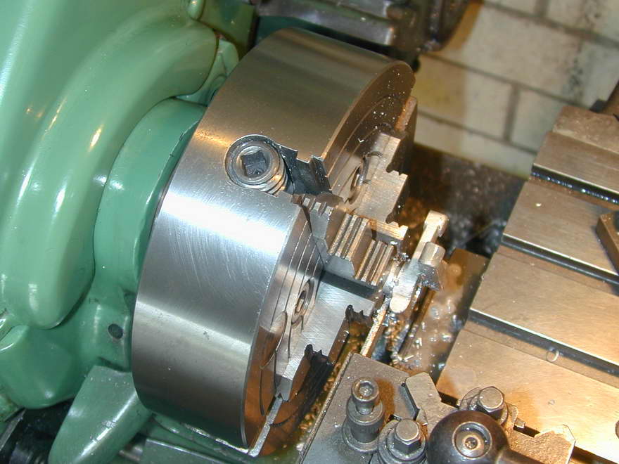 The timer can now be parted from its spiggot. You'll find that the casting is oversize in all dimensions with respect to the drawing, so don't worry about maintaining the stated 1/2" distance. Just part-off where the casting ends and counterbore the side facing the cover later to bring the outer face in line with the end of the cam bush.
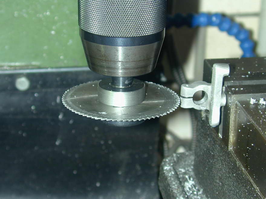 The arm can now be clamped in the mill vice to mill the top of the spring attachment and adjustable point bosses flat. At the same setting, drill and tap the spring and fixed point holes 6BA, spaced 1-1/4" apart. Drill and ream the hole for the actuating rod over the center line of the bored mounting hole. This not because any precision is required, but simply to ensure a smooth, low friction and low wear finish for the fibre actuating rod. Finally the frame is rotated 90° for drilling, counter drilling, and tapping the clamp bolt hole (also 6BA). The frame can then be slit at the bottom to allow the clamping bolt to draw the sides together.
The kit includes a length of insulator rod for making the moving contact insulator bushes and the actuating rod. You'll end up with more swarf than component, but that's life. Make the lifting rod a close sliding fit in the reamed hole and leave it over-length so it can be finished to the precise size required later.
The spring is made from fully tempered spring steel. This is not supplied with the kit so I've used a piece of 0.016" thick stock that was once used as a binding strap on a wooden packing crate. The half-moon cut-outs set the point at which the spring will flex. It is important that the tungsten points meet squarely, the reason being that while it is a hard, refactory metal, resistant to pitting and accidental welding, tungsten is not a very good conductor of electricity. So if the points are mis-aligned, or do not come flatly together when closed, the intersection surface area is reduced and the electrical resistance is more than it could otherwise be. So drill the mounting hole undersize, then open it out with a needle file to take the insulating bush so that you get the best possible registration of the points.
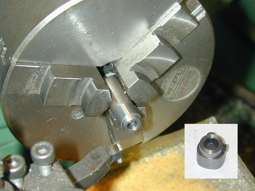
The last job is the contact breaker cam. I really did not like Westbury's taper pin attachment idea; it's just too permanent (and I don't have a stock of taper pins and taper pin reamers, though a model engineer with a live steam background may have). The alternate is to secure the cam with a hex head grub (set) screw. Experience shows that a single set screw will ultimately come loose, even when cinched within an inch of destroying the hex socket, while two such screws positioned at 90° to each other will hold forever with only moderate tightening. The cam flat could be filed, but I've chosen to turn it using the old out-of-phase 3-jaw chuck assembly bodge. This is described in the Sugden crankshaft page and gave the desired result with very little effort.
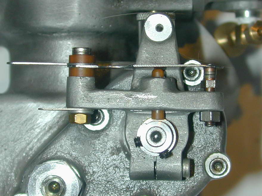
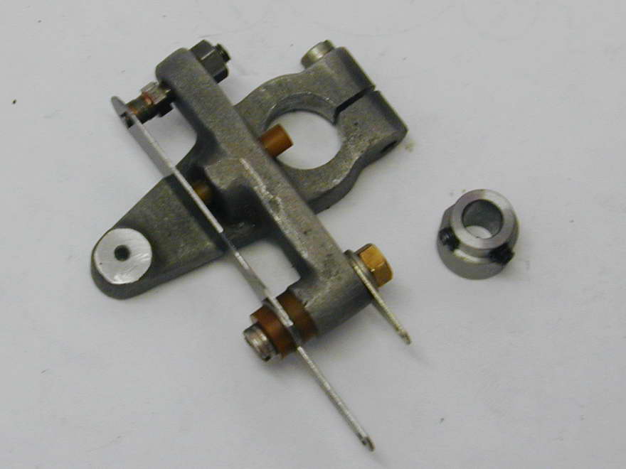
And here's the finished result. I'm no where near as experienced with ignition engines as my Motor Boys colleagues and Ken Croft advises that points like this are best used in the "traditional" way, which is to say, carrying the full primary coil load, not used to drive a transistor assisted switch. The reason being they are relitively high resistance items and exposed to oil contamination which makes things worse. The full primary current load will tend to burn away the oil. A transistor switched circuit will pass only a few milliamps through the contacts, so this "self-cleaning" action does not happen.
If you have no stockpile of tungsten points, substitutes are possible. Contacts cut from tungsten welding rod with a diamond impregnated abrasive disk and brazed to screw heads are practical, if tedious make. I've also read that fully hardened drill rod is not bad when used in conjunction with a transistor switch. This reduces the point current and so reduces arcing and pitting. The points will still oil up, but as drill rod is a much better electrical conductor than tungsten, problem onset is delayed. However, there is another solution, even if it is not quite so in keeping with the spirit of the Whippet design: fully pointless ignition!
Dwell
The points, coil, capacitor, and battery ignition system is known as Kettering Ignition after Charles Franklin Kettering who devised the system that first appeared fitted to the 1910 Cadillac (along with the then traditional magneto). Before going on to the next section, some mention should be made of dwell, named after Fred Dwell who... (joke!  I don't know what came over me). "Dwell" can mean many things, but in this context it refers to the angle of cam rotation during which the ignition points are closed. Obviously, this is the time period during which current flows in the ignition coil primary winding. Equally obviously, for a specific angle, the time period will vary with engine speed and cam diameter (and point gap, but let's ignore that).
The coil needs current to flow in the primary winding for a certain minimum time in order to produce a decent spark when the current is interrupted. Too short a time and the spark will be weak, or non-existant. But extending the time past an optimum value just drains the battery and excessively heats the coil. Selecting the "dwell angle" then becomes a compromise between producing a hot enough spark at maximum revs and not destroying the coil at idle speeds. As the characteristics of coils vary, it is not practical to quote a simple formula. Better to consult the maker's data for the coil (if you can get it) and tailor the dwell period as "so many degrees on a cam of such and such a diameter" for a maximum and minimum rpm of xyz.
Hall-effect Ignition Timer
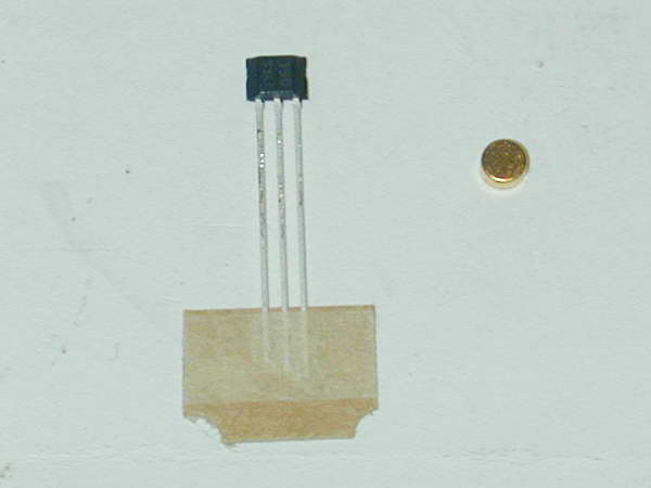 The Hall-effect ignition timer is an extension of the transistor switching mentioned above. Basically, a transistor is a slab of semiconductor material with carefully introduced impurities in strategic locations, to which three wires are attached (I simplify greatly). By applying an electrical potential across two of the connections, the usually non-conductive material passes a small current that is used to control a larger current between another pair of connections. In effect it becomes a current amplifier. This allowed us to reduce the current through the ignition points to a few milliamps, yet still pass the required high current through the primary winding of the ignition coil during the time when the mechanical points were closed. The Hall-effect transistor is a similar device except that switching is effected by a magnetic field instead of an electrical one. This allows us to replace the mechanical contacts and cam with a tiny rotating magnet, hence the term "point-less ignition".
...to be continued...


|
This work is licensed under a
Creative Commons Attribution-Noncommercial-Share Alike 3.0 License. |