Cirrus Construction Log: Pistons and Rings
Created: October 2005
Updated: September 2006

Pistons
 The piston castings are neatly cored with reinforcing bosses around the wrist pin location. As usual, the important thing is to ensure that the wrist pin hole is normal to the axis of the piston and that is located accurately. After reading Eric Whittle's sequence for maching the casting, I decided that there was probably no way of improving it. The photo sequence below shows:
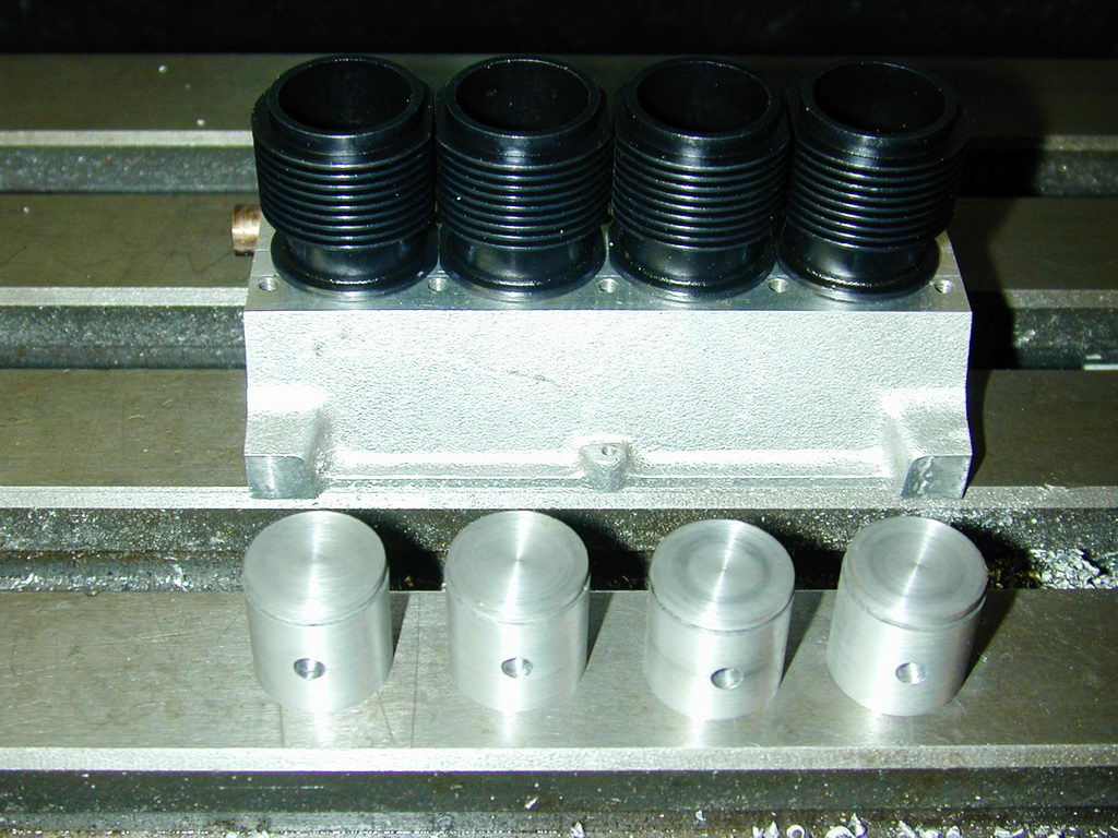
- The rough castings are chucked and the end casting flash turned away. The lower skirt is then opened out to 0.625".
- To ensure all are the same, a plug gauge that will later be used as a mandrel is used to test for a close sliding fit in the end of each piston, up to the start of the wrist pin boss.
- The castings are then reversed and the top faced back to clean up flatly. At this point, the only the base of the piston and the bored ID need to be aligned.
- The mandrel used as a gauge is now chucked and clocked to turn with less than 0.001" of wobble. Each piston is placed over the mandrel and pressed home with a pressure pad held firmly in place by a live tailstock center. The OD is turned to clean up all over, but about 0.020" oversize. If the mandrel is a close fit in the skirt, the OD is now concentric with the counterbore and mandrel.
The pistons can now be gripped in the 3 jaw chuck and the skirt faced away to locate it the correct distance from the inside top of the piston (0.602") with reasonable confidence that the skirt will stay normal to the OD. The pistons could now be faced to final height (0.695"), but I decided to wait as the exta length helped the next step.
- The piston is now clamped to a V block which has been aligned on the mill table to drill and ream for the wrist pin. The arrangement allows the inner wrist pin bosses to be aligned by eye before clamping up. The base of the piston is used as a reference (located by a GHT edge-finder). After locating, the Y axis is wound up to give the pin location of 0.313" above the base. The X location is found by traversing a 2mm slot-drill across the piston to cut a small flat in which a pointer gripped in the drill chuck can be visually centered. Center drill, drill 9/64" and ream 5/32".
- The pistons can now faced back to their final height. They are then returned to the mandrel (again, clocked to run true) to be finish turned to 0.0025" (thereabouts) smaller than the cylinder bores. I'd taken care to make my bores identical within 2 tenths, so all could be the same diameter. But for safety, each piston was stamped inside the crown with the cylinder number it was destined for. Finally a 0.033" wide compression ring grove is cut 0.050" deep so that the lower edge is 0.083" from the piston crown. The land above the ring is then reduced in diameter by 0.020". This assists getting gas pressure behind the ring and allows for some expansion of the piston crown which will be hotter than the material under the ring.
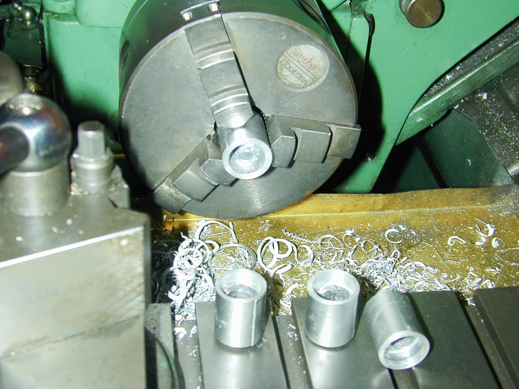 Photo 1 |
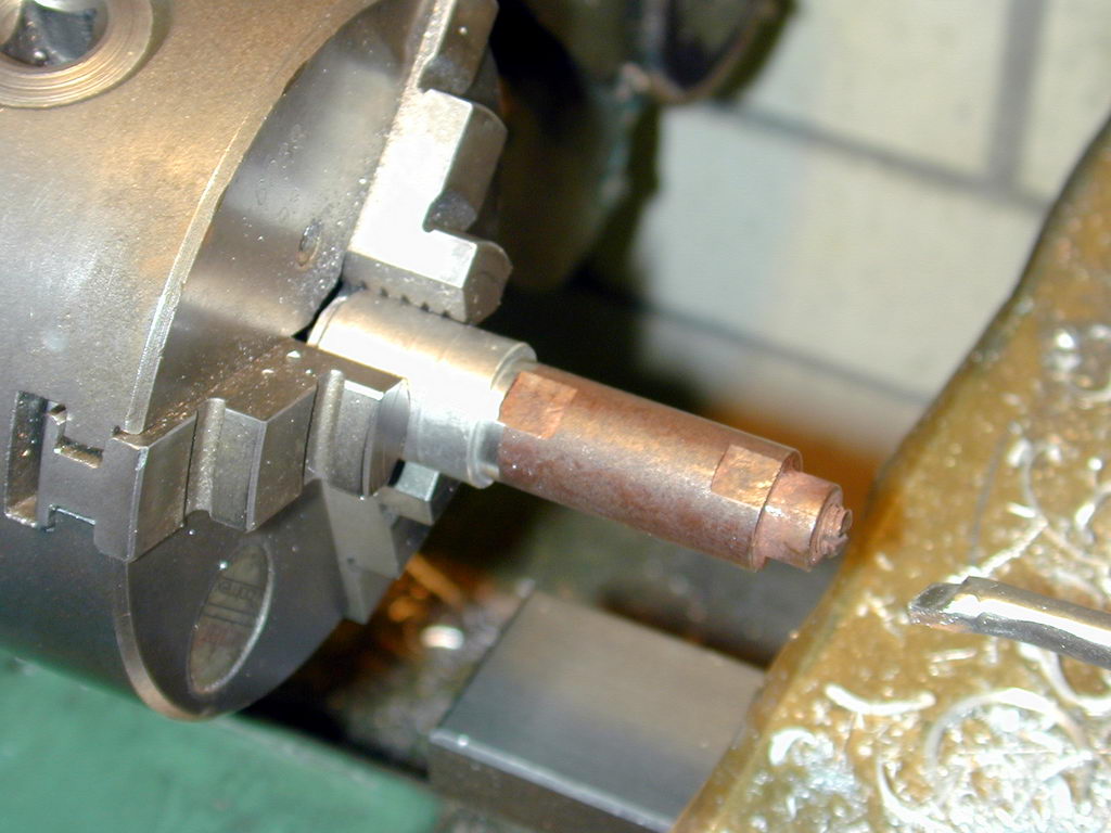 Photo 2 |
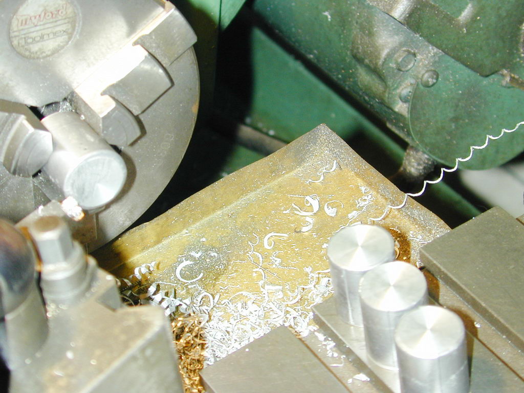 Photo 3 |
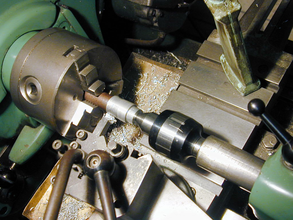 Photo 4 |
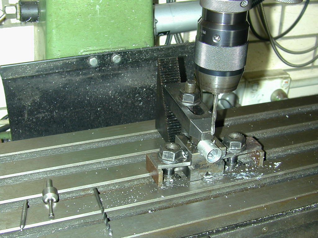 Photo 5 |
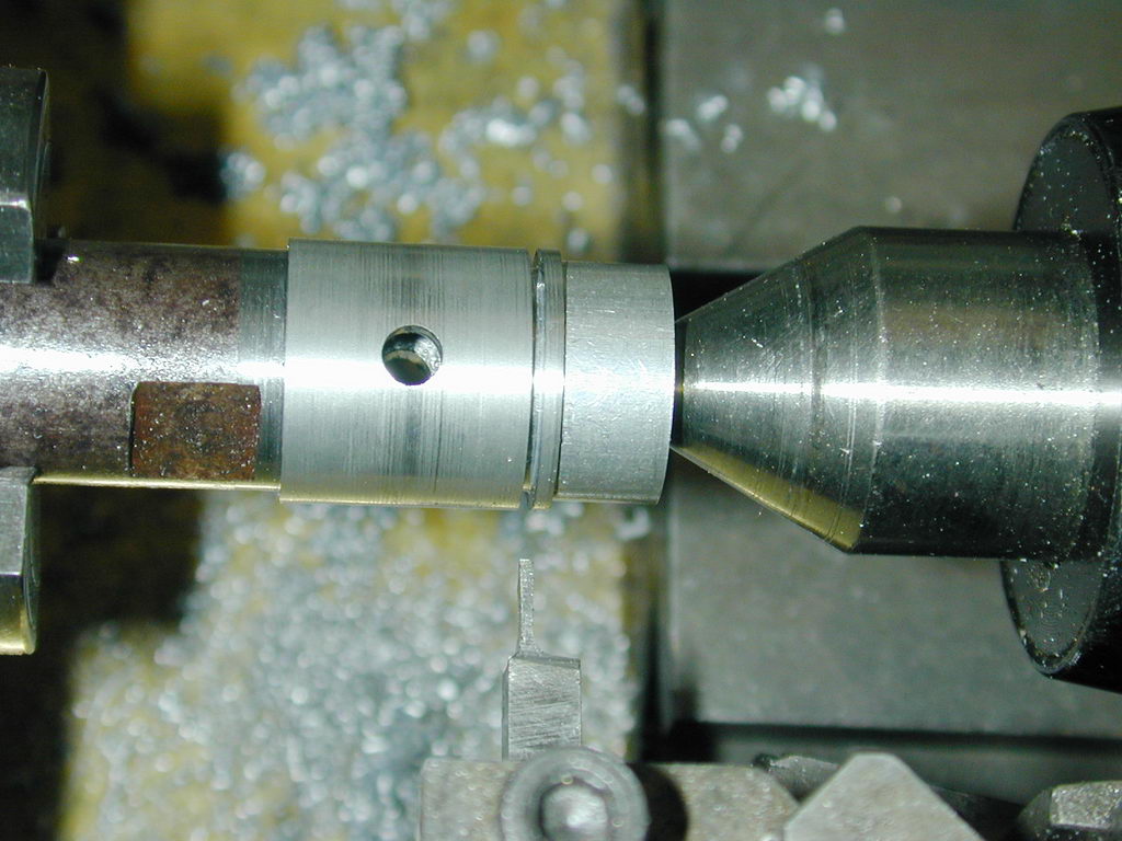 Photo 6 |
This completes work on the pistons. Total time about 5 hours. I did not like turning the pistons to final size over the drilled wrist pin, but it went ok.
Wrist Pins
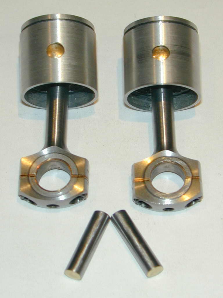 In contrast, the wrist pins did not go quite so well. What should have been a straight forward task ended up being complicated by a cunning plan to shave a bit of time off the construction. Read about it in the Tech-Tip for August, 2006.
Rings
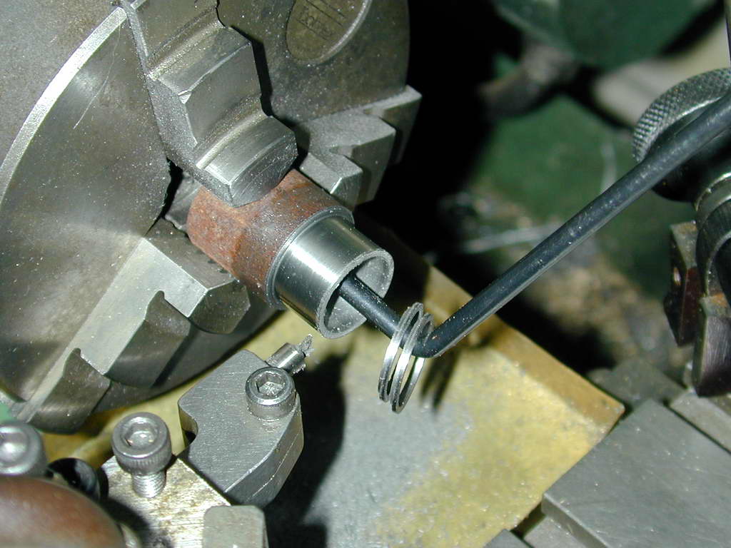 The rings are another straight-forward job. This process, which is based on the "Trimble" method, is described in the Feeney Construction Log, so we'll just hit the highlights here. Recall that I took great pains to hone all cylinders to within a couple of tenths of each other so that one size ring would suit all. Here a length of cast iron has been bored to 0.600" and turned down to 0.692" before polishing to a close sliding fit in the largest cylinder bore. The rings are then parted off 0.001" over size (0.034"). The first two rings parted off are discarded in case the polishing effort produced a taper. This still gives material the four rings plus two spares. Note how the scriber block catches the rings as they are parted off.
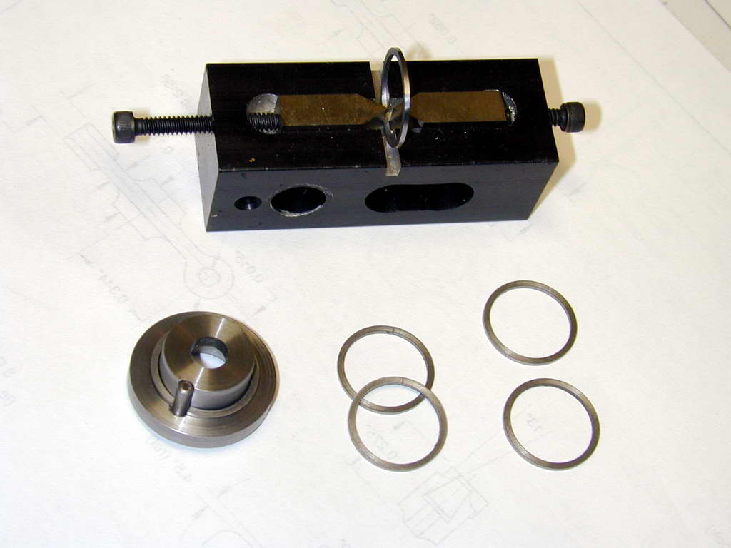 The little Trimble ring clever is used to radially split the rings. In this photo, the two on the right are un-cut; the two in the middle have been split (12 o-clock position in the photo). On the left is the Trimble-style heat treating jig with one ring stretched open. Notice the easily visible space between the inner ring face and the central spigot of the fixture at 90° to the gap pin. This clearly shows how a ring gapped using the Trimble method is not even remotely circular in its relaxed state.
 In a slight departure from the basic Trimble jig, the one shown on the SIC plans by RAW has an extra pin opposite the gap setting pin. This is intended to ensure that the ring stack is correctly pressed against the spigot at the point opposite the gap pin. Unfortunately, the drawing has an error. If drilled as shown, it will not be possible to fit the rings onto the jig as a 0.045" radial ring width will not fit in a 0.015" space! This may have been mentioned in an SIC errata, but the problem was obvious from the dimensions, so no big deal.
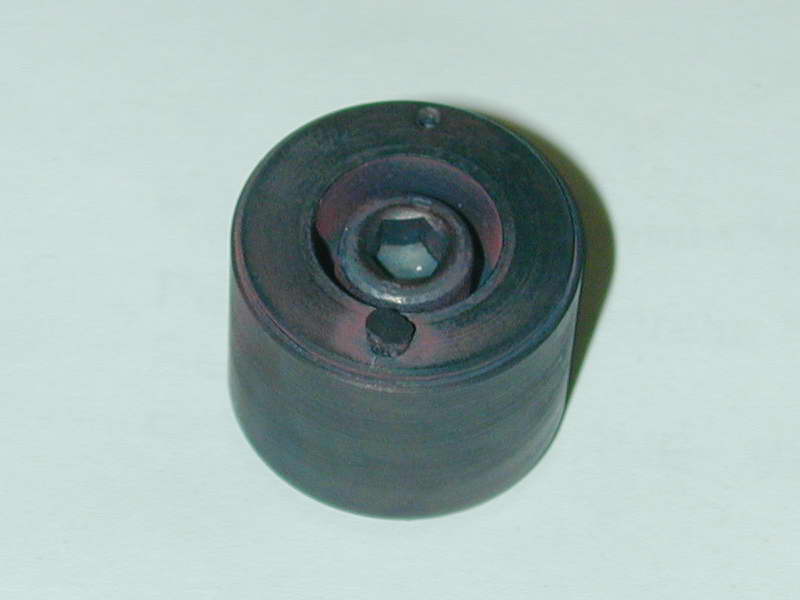 Here we see the annealing crucible after heat treatment and cooling. Note the turned steel cover that fits over the fixture to keep the air out to prevent scaling. This is similar, but not identical to that described by William Schaeffer in MEB issue #7. Naturally, I think my version is better, as explained in the referenced editorial page
  .
.
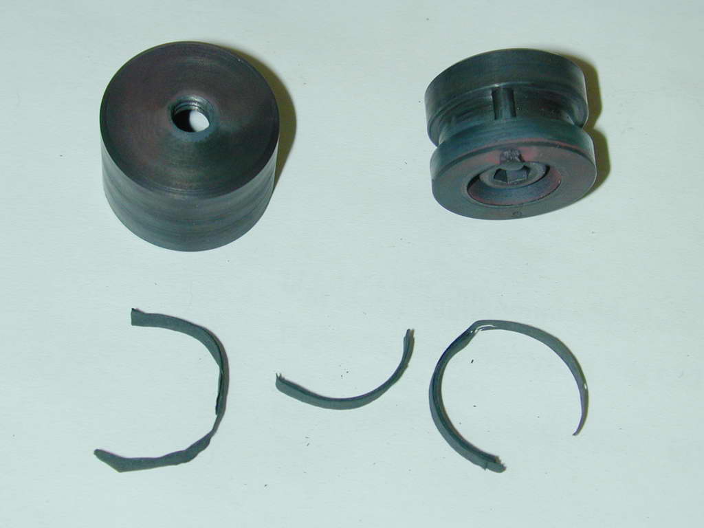 Photo 12 |
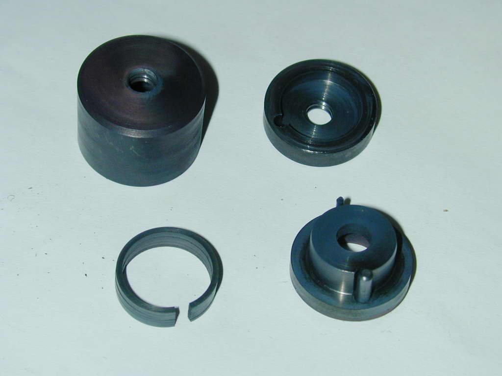 Photo 13 |
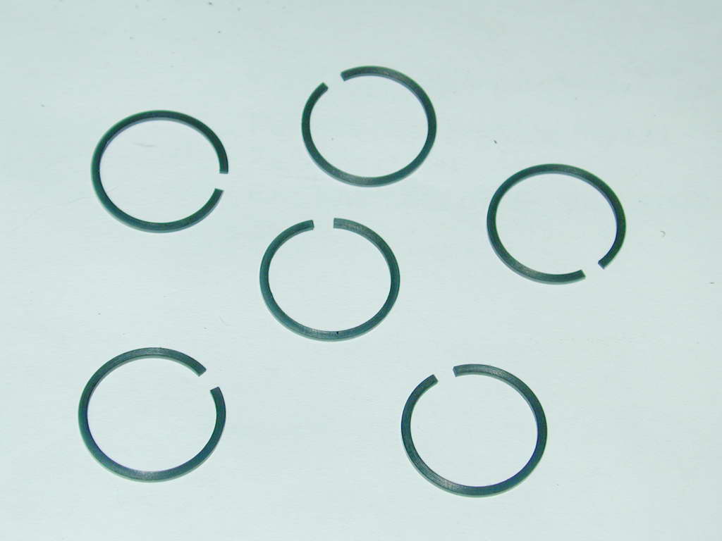 Photo 14 |
Plain brown paper is packed into the free space in the fixture cavity. Its purpose is to consume any remaining oxegen in the fixture as the heat rises. After heating to red and air-cooling, the crucible is opened. The degree to which the air has been excluded is indicated by the brown paper. If it flashed, the fixture leaked. So far, so good (Photo #12). The next indicator is does the spread ring close up then removed from the fixture? As seen in Photo #13, the rings have permanantly taken up their new, optimum shape and can be simply dropped back onto the fixture. Photo #14 shows four rings and two spares. Next, the gap must be filed and the rings polished top and bottom to fit the piston ring grooves.
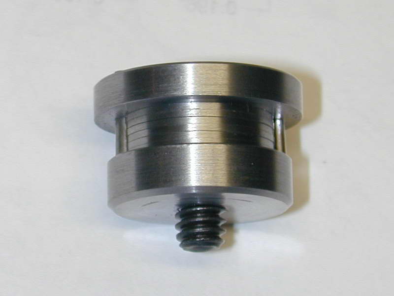
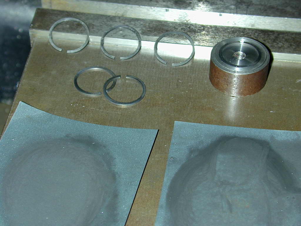
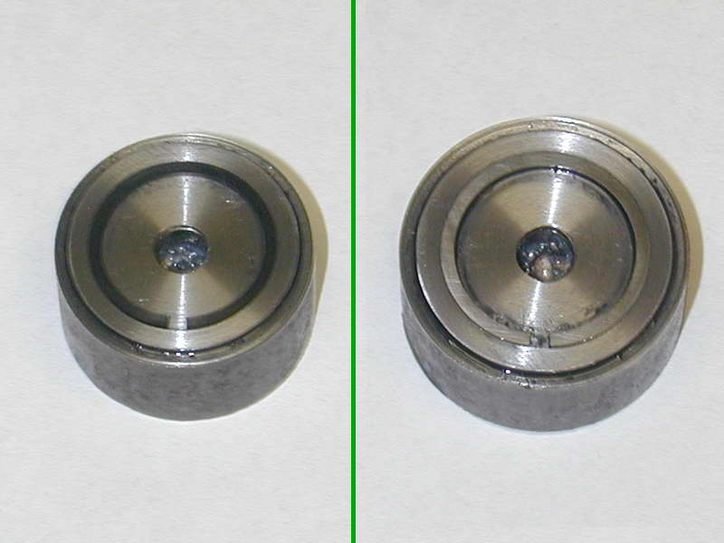 This simple gadget provides the best chance of uniformly polishing the ring faces—necessary to minimise gas leakage, and reduce the ring thickness so that when pushed down onto the lower face of the piston ring groove, there is sufficient space to allow gas pressure to get behind the ring where it can force it out against the cylinder bore. To ensure a uniform ring width is retained during this process, a simple jig is required. It is a simple recess bored in a steel off-cut. I don't believe there is any point fully compressing the ring for this operation, even though this means the ring will contact the bored out cavity at three points at most. The compressed ring is 0.683" in diameter. After annealing, it is about 0.73" across the major axis. the Fixture is bored 0.712" to a depth of 0.32". This photo is a composite showing the before state (left, blue from annealing), and after polishing.
 And what is the correct ring thickness, you ask? The Rule of Thumb for model engines with a bore under 1" is between 0.0035" to 0.0015" smaller than the ring groove for the top ring, and 0.0025" to 0.0010" for any lower rings. The rings are polished and their thickness reduced by rubbing lightly on 800, then 1200 grit glass paper, generously dosed with light oil, using a circular motion. Naturally a very flat surface is required to back-up the glass paper. If the rings were bigger, I'd pull out the surface plate, but for these, the top of the mill vice is adequate.

One important point, clean the jig and ring thoroughly before insertion. Any contamination under the ring will probably result in a wedge-shaped ring. Also, the more material you mush remove, the greater the danger of sanding in a wedge andle. I've found making the rings 0.001" oversize provides enough material to comfortably clean up the faces without having to remove so much material that wedging becomes a danger.
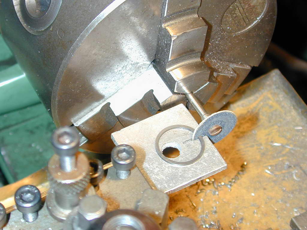 The last operation is to polish the ring end faces and set the gap. The ring will be the hottest part of the engine when it is running, so it will expand. The gap is to accommodate this expansion. There are a number of opinions of what the operating gap should be for model engines. These range from 0.004" per inch of bore, to none at all! Having tried both, I lean towards the latter for bores below 25mm (1"). In actual fact there will be a small gap as we must clean up the rough faces left by splitting the ring. This photo shows a simple set-up to do this using a disk of fine glass paper spun in the lathe. The "table" is just a piece of plate with a saw cut in it (ignore the hole) held horizontal in the tool post. This ensures the ring faces will be vertical, allowing you to concentrate on presenting them flatly to the disk. As the ring was made to be a "piston fit" in the bore, this operation will introduce a slight gap when the ring is fully compressed.


This page designed to look best when using anything but IE!
Please submit all questions and comments to
[email protected]
Copyright (c) Ronald A Chernich, 2004-2005. All rights reserved worldwide.