Editorial
The Cirrus head is finished! And although I had not planned to, a lot of words seem to have been typed regarding how it and the two manifolds for it were made. Must have been all the photos. There are 90 of them, not including the thumb-nails. Or maybe I just got carried away, again.
We also have a lot of other reading for you this month. There are two new David Janson engine reviews and another piece from the ETW archive. I had not planned to prepare two Janson OCR jobs, but one was done early in the month, and a photo arrived from a reader that just begged for the second to be done, so there you go. To those of you out there who have sent me stuff that has not appeared here yet, I truly appreciate it. The filing system is under control now, so please be patient—I'll get around to it.
My "day job" has me writing portable code in C/C++ again for the first time in 10 years and being moderately amazed at what a low-level and error-prone process this is in comparison to Java. It's like having to machine all you own screws and nuts instead of using standard, reliable, off the shelf ones. Oh wait—I've just done exactly that for the Cirrus... Still, regaining lost and forgotten skills is enjoyable.
Can't say the same for the weather Down-under though. The drought here in the Wide Brown Land just goes from worse to worse. There are now entire country towns without water who have to truck it in. The city where I live goes to "level 4" water restrictions starting next month requiring all pool owners in a city of nearly 2 million to fit pool covers to reduce evaporation. You can bet someone will make a bundle out of that, and sadly it won't be me. Orders for the MEN Only CD seem to have dried up as well. I'm considering offering a low-cost, renewable subscription that provides 12 months access to the Members' facilities. CD owners have lifetime access (my life, that is  ). Administration will be a bit of a pain though. Let me know what you think. Now to business...
Cirrus Progress
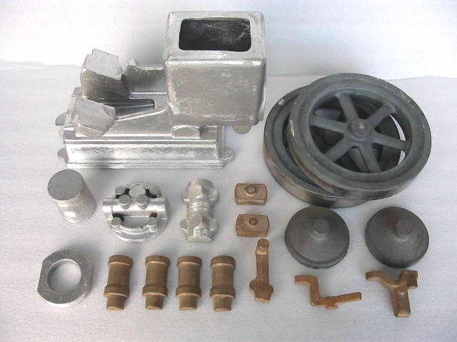
Finished! Well, all the parts have been made with the exception of the valve push-rods. Assembly will take a little longer. My "raw" file contains 156 photos taken while making the head, manifolds, and hold-down studs. These have been winnowed down to a mere 90 and appropriate words added. Because of the volume, the head part of the Cirrus Construction Log has been separated into five pages. I don't know how many read the words and how many just look at the pictures, but any prospective Cirrus builder will find some notes on problems with the drawings that will be of value. There's also a giant boo-boo confession.
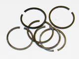 The piston rings are now fully finished and the Cirrus Pistons page has been updated to show the annealing fixture. The fixture I have standardized on for annealing is very similar to that described in the issue #7 of MEB (see this month's Book of the Month). It may come as a surprise, but I humbly assert that my fixture is superior. Read why in this month's Tech Tip.
Next step is to fit the center crankshaft bearing shells, cut some gaskets, assemble the thing, troubleshoot any binding, make a motor mount, run-in the rings, make the plug leads and driver, etc, etc. Hmmmm. Maybe I'm not as "finished" as I thought...
Mills Magic
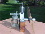
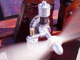
While the screw-top glass jar tank would be more at home on a Genie, or a Thor, the rest is pure Mills Magic: a MkI 1.3 with a MkII venturi assembly. I'm really pleased to see this as it represents the first picture I've been sent of an engine built from my plans that appeared in MEB #1. Click on the picture for the story. And as an aside, the Genie and Thor mentioned were AHC "slag" sparkers. Tim Dannels' Model Engine Encyclopedia tells us that the Genie was a Thor with the cast "streamlined" fines turned circular. Bert Streigler says that "thor" is what your fingers got trying to start them!
Majesco Mite Again
Last month we showed a picture of Les Stone's Majesco Mite under construction. Well, as expected, Les has now completed his replica and has run several tanks through it. He reports that while it's no power-house (no big surprise), it starts easily and handles well. For more pictures of Les' Mite, visit the updated Les Stone Tribute page.
All Steamed Up
Sometimes I get confused regarding what these pages are about. It's information, both old and new, regarding model engines, their design, and the techniques used in their construction by model engineers and commercial manufacturers. In other words, this is not Strictly Internal Combustion and it's ok to occasionally talk about external combustion.
 Last month an email arrived at Enquiries that was not Spam, but a plea, on behalf of the sender's neighbor, for help obtaining plans for an ETW design called the Theseus. Seems his friend had been building one for so long the plan had faded to unreadable. Did I know the plan number and where it could be obtained? The Library supplied the first answer (M.19), along with the issues of the Model Engineer in which it had appeared. For the second answer, I figured that the best plan was contacting TEE to see if they could supply the required back issues of the ME. This they did, and the builder is most happy.
All this took maybe 30 minutes and having done the research for one of ETW's steam designs, it seemed like good future-proofing to collate them all on a page similar to that which lists ETW's IC Engine Designs. So visit the new ETW Steam and Stirling Engine Designs page for a table showing the remarkable diversity of ETW's designs. There are still a few unknowns on the page, so if any reader can help complete it, drop us an email.
The Inside-out Rotary
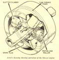
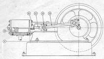
While talking about ETW, one of his writings on unusual internal combustion engines has been added to the ETW Tribute page. This concept seems to surface again and again. The last time it was mentioned, we looked at the Mawen Differential Rotary that snuck an extra bang into each 720° cycle by rotating the cylinders and the crankshaft. This same design resurfaced in SIC Vol 12, Issue 67 of Feb/March 1999 where Australian Colin Clifford's differential radial was described. Patent claims aside, the Mawen and Clifford are virtually identical and both trade off a moving part count reduction against the difficulty of sealing the open rotating cylinder tops against a fixed head ring. In his 1962 article, ETW describes another approach by Mr AC Mercer that solves this problem by inverting the cylinders. The Mercer and the Mawen/Clifford engine are really different beasts though. The latter are master/slave rod radials that happen to be rotaries as well, while the Mercer is piston-ported, 2-stroke, cam-track radial. As you'll read, Mr Mercer had already built a working model in 1962. Although no detailed plans are available, a talented model engineer could build a working one with no great difficulty.
MiniTech Website Upgrade
Australian readers may like to visit the new-look MiniTech web site. They've also added pages for customers' model pictures and a "Forum" page. The gallery is largely steam, although there is one nice freelance hit 'n miss design and another hopper cooled one made from a kit available from MiniTech. I could almost be tempted, but it's a big bugger, 38mm bore and 54mm stroke. I don't have that much room under my bench!
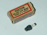
Driving Glow Plugs
As we all should know, the "glow-plug" is a coil of platinum-iridium wire that is initially heated to incandescence by passing a current through it. This, together with compression of the air/fuel mix, is sufficient for ignition to take place. Once the engine has started, the current can be turned off. Continued heating is provided to the plug element in three ways:
- Conducted heat carried over from previous combustion,
- Continuing compression of the fuel/air mixture, and
- Exothermic (heat releasing) catalytic action between the alloy and the methyl alcohol in the fuel.
Over the years, I've heard an astounding amount of rubbish spoken at various model flying fields about the "correct" way to light-up a 'plug. It's just basic Ohm's Law, folks (E=IR). The wire element has a resistance. This may vary slightly from plug to plug, but is kept within a narrow range by the manufacturer. A voltage applied across the element causes a current to flow. The IR loss results in the wire getting hot. Since the resistance (R) of a given plug can be considered to be fixed, more voltage (E) results in more current (I), causing more heat. Too much heat (from too much E, and hence, I) and the wire melts.
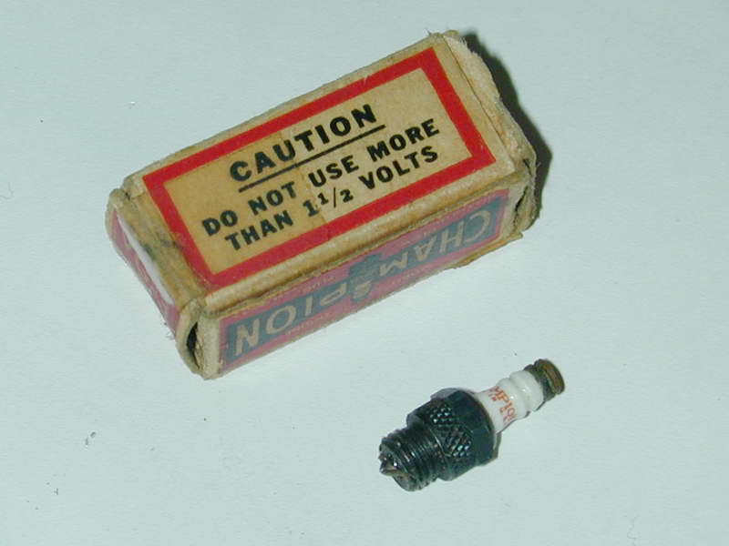
In the old, old days, we used a 1.5 volt "telephone" battery that always seemed to go flat during competitions. Rich kids got themselves rechargeable, 2 volt lead-acid accumulators that could be charged up the night before the comp and leaked sulphuric acid down their back as they peddled to the comps (ask me how I know ). They also used long plug leads to (hopefully) drop the voltage that appeared across the element to a safe level. Then manufacturers introduced "2 volt" plugs and life got complicated.
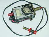
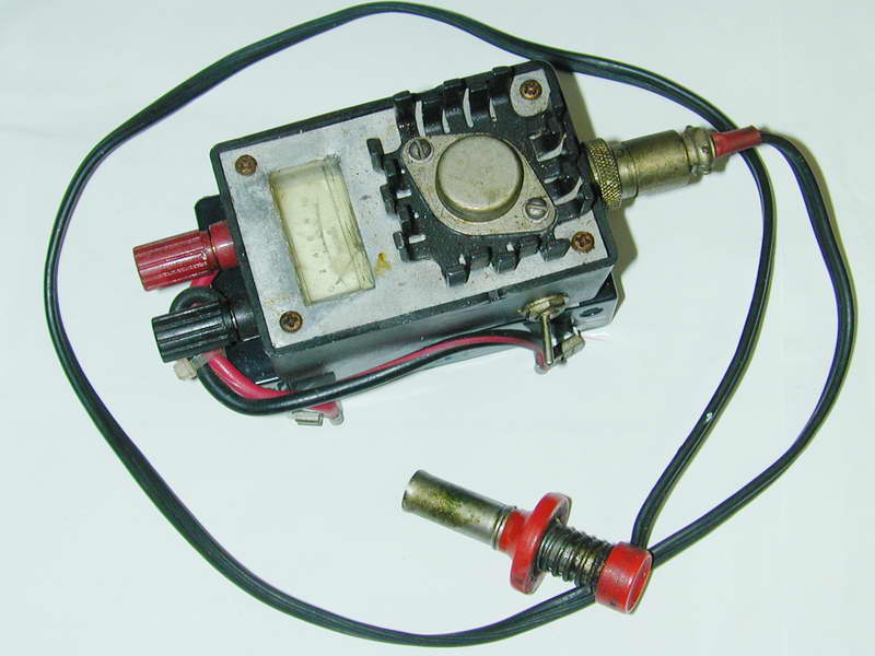
Today, most modelers seem to use a "Glow-driver" gizmo that they've paid an arm and five legs for at the local R/C hobby store. These use a 6 or 12 volt supply and perform some wizardry to effectively do the same IR thing with the plug element that the telephone battery did. Their internals can vary enormously from a DC constant current source, to a pulsed voltage where the combination of the "off" and "on" times results in an average current to satisfy the IR requirement. The circuits involved are relatively simple and the component count is low; why they cost so much, I'll never know. The photo shows the current regulator type I made nearly 20 years ago that has served me well through many battery replacements.
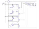 Real Soon Now, I'm going to have to light up four glow-plugs at once for the Currus. I was thinking of a new version of my standard unit with more volts a bigger heat sink when an email arrived from Jerry James, designer of the Hex2 that we looked at earlier this year. Jerry has come up with a rather innovative solution for multi-cylinder glow engines. It's based on the pulsed voltage approach, but introduces a multiplexer that is constantly and sequentially cycling the pulse to the plugs. Only one plug is "on" at any one time, but this does not matter as during the "off" time, a pulse is being applied to the other plugs, round-robin fashion. Jerry has a prototype running and is considering selling units either ready-make, or as a kit of parts. You can contact him through jerry(at)jamesengine.com.
Supper is served, Your Hiness
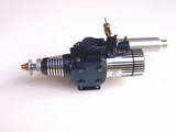
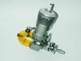
The variety of exotic models that the Hiness Corporation has produced over the years is remarkable. Some time ago, David Owen kindly pulled his Hiness 3 cylinder two-stroke radial apart for us. Last month we saw pictures of some more Hiness engines in a Singapore model shop museum case. This past month, a reader has supplied individual pictures of several of the types glimpsed in the display case, plus several others. These have been added to the Engine Finder. The engine heading this news item is the Hiness Arrow 60, an engine with quite a history to it as explained in David Janson's review. It may even explain the terrible title for this entry!
New Books and Magazines This Month
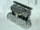
Issue number 7 of Model Engine Builder arrived this month. This issue contains full plans for another of the late Hamilton Upshur stationary engine designs. This is a horizontal opposed twin that uses the built-up crankcase construction featured on many of his other designs. Other articles featured in issue #7 include using a mill and an off-set fixture on a rotary table to machine the flanks of cams for four-stroke engines, some tooling ideas, and articles on outstanding examples of the model engine builder's art. The issue runs to 40 pages (excluding covers), with another 10 large format drawing sheets. Editor Mike Rehmus has decided to abandon his earlier "complete in each issue" policy for construction features, so the Upshur Twin will conclude next issue. For a quarterly journal, the earlier policy was a necessity—who would want to wait three months for the next set of drawings to arrive? But with the new bi-monthly schedule, splitting articles to provide broader content in each issue is acceptable. If you haven't subscribed, you should.
As announced in this issue, the Model Engine Builder web site now has a password protected area for subscribers. This will contain articles that do not suit printed publication. The first is a "virtual rotary table" spreadsheet idea. In addition to the password, there is a click-through agreement page. Nice idea. I'll think about it...
Engine Of The Month: Super Cyclone GR
This month I've wimp'd out again and prepared another page extracted from David Janson's Engine Reviews. I have to admit to a less than burning passion towards sparkies. I'm sure this reflects my childhood experience which was all diesel. But there are a few ignition engines in my collection, this modern Super Cyclone being one of them and David's treatment is better than anything I could put together. So visit the fully expanded Janson Review Index and seek out the active links to OCR'd reviews, which now include the Cyclone.
Tech Tip of the Month
By coincidence, issue #7 of MEB contains a short article by William Schaeffer in which he describes a fixture that is almost the same as how I prepare my ring annealing crucibles, but not quite. To those who have just read that article, I thought it timely to offer a slight variation for your consideration.
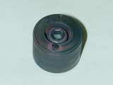 We both use the Trimble fixture, but with a close fitting cover, or shroud over the base and clamp. This keeps the air out during heat treatment. Our reason for doing this is the same too: to avoid the formation of scale during high temperature annealing. The pure Trimble method coats the ring stack with PBC compound that vitrifies under heat and so excludes air as the ring material passes through the critical temperature. William's fixture as illustrated in MEB uses a separate nut to secure the clamp. This is followed by the cover, and another nut. There is nothing really wrong with this approach, but that inner nut means an extra air pocket and the whole purpose of the cover is to exclude air and hence prevent scaling as the rings pass through the critical temperature.
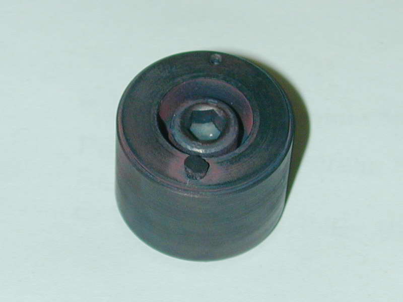
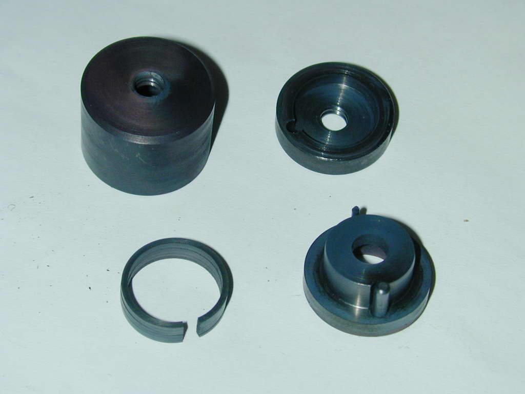
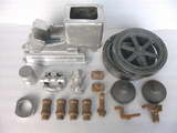
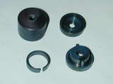 In my version seen disassembled here, the clamp and the cover are both tapped 1/4-20. To assemble, the rings are slid onto the fixture and a cap head screw inserted into the cavity in the central post of the gap-setting component. Next, the clamp is secured down to centralize the rings and press them flat. After packing the space around the rings with brown paper (as described by Trimble and Schaefer), the cover is just screwed down over the whole lot, resting flat against the clamp disk. No nuts, and no extra air pocket.
You might like to plan ahead and machine the recess in the clamp and the length of the cover to accommodate the maximum and minimum number of rings you ever plan to anneal in the fixture. The one here will do 2 to 6 rings.
 Cirrus Progress
 Editorial