Building the Sugden Special
Modified: April 2006
August 2007
Click on images to view them full size.
A builder tacking a project like this should be comfortable with basic techniques, so this page will cover only the more unusual aspects of construction, plus some recommendations regarding worthwhile changes for prospective builders.
 Introduction
Cylinder Liner
Conrod
Crankshaft
Venturi
Pistons
Assembly and Test
Modification and Re-Test
Introduction
Cylinder Liner
Conrod
Crankshaft
Venturi
Pistons
Assembly and Test
Modification and Re-Test
![]()
Introduction
The Sugden Special has been on my list of "must build someday" engines for almost as long as I can remember (which can be as distant as last week, on a good day  ). The full history of the engine is given on the Sugden Special feature page. When writing that page, I searched in vain for a finished Sugden. My pal Eric Offen sent photos of three genuine original, rough as guts castings he's made a start on, and most generously mailed one off to me to complete. The work that Eric had completed was to bore out the case, ream the journals, and turn up a backplate.
I'll classify it as an intermediate level project as it requires thread cutting and some rather precise set-ups when making the cylinder transfer and exhaust ports. And the dual diameter crankshaft journal would be a bit tricky for an absolute beginner. The rest of the machining however, is quite straight forward.
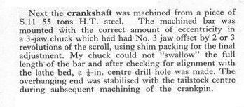
In his original construction series, Dave Sugden described a somewhat unusual way of machining an overhung crankshaft. This was faithfully followed for authenticity and amusement. The approach was mentioned briefly on the Crankshafts How-To page, but having now tried it, I can offer some concrete comment on what I see as the advantages and disadvantages offered.
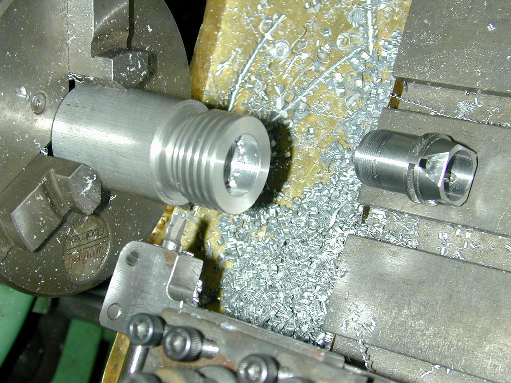
When machining a cylinder liner of this type, the prime consideration should be how can the blank be held so that can be bored from the bottom while permitting seat to be cut at the same setting, without any danger of the chuck clamping forces causing distortion. The upper section of the liner is threaded 40 TPI for the cooling jacket. To facilitate testing the screw fit, the liner will need to face the other way for this operation.
Sometimes cylinders like this require a sacrificial chucking piece. After some thought, it was decided to form the threaded section last. The sequence I decided on for the Sugden avoids the need for a chucking piece, while meeting the other criteria.
Note that all the heavy work was done while the thickness of the blank clamped by the chuck jaws was at a maximum after drilling and boring. Even if the porting operations disturbed the blank slightly, subsequent operations ensure that the bore will be normal to the seat, and that any taper caused by spring-back in the boring bar acts to place it where we want it—ie, narrower at the top. I always make multiple passes of the boring tool at the same cross-slide setting as I approach the finished size. The amount of metal removed with no change never ceases to frighten and amaze me.
Advantages
Disadvantages
Cylinder Liner
The liner for the Sugden drops into the case and is secured by a hold-down ring which presses against an exhaust flange that also provides the primary compression seal.
 The area above the exhaust flange may not be *perfectly* concentric with the bore. But it will be close enough not to be noticeable and it is of no consequence to efficient operation anyway. All it has to do is provide a place for the cooling head to screw onto. When making the cooling head, bore to be a close sliding fit on the cylinder to maximise thermal coupling between the two. You can cut the thread in the jacked a bit "loose" to prevent it binding as it is tightened.
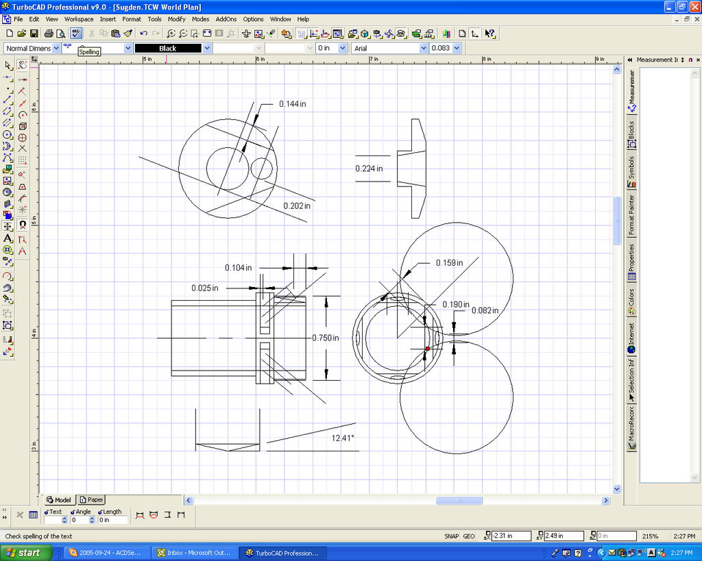 I find a CAD drawing program invaluable for determining reference points and offsets such as the size and position of the step used to locate the transfer port entry point, and the depth a 1" slitting saw will need to be plunged from first contact in order to leave the correct amount of metal between the ports. It could be done other ways, but life's too short.
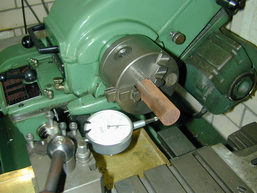
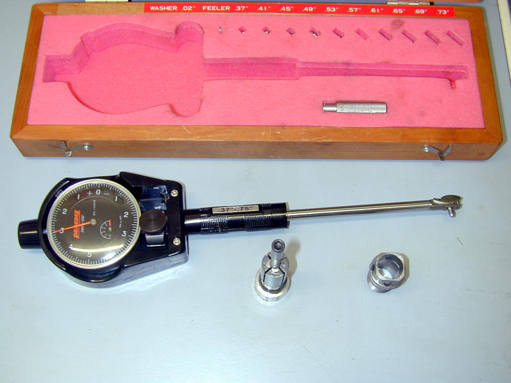 The final job is to lap (or hone; I'can't make up my mind which term is more accurate in this case) the cylinder to a fine, fully circular finish, with a light taper of about 0.0005", narrower at the top. The actual size is not greatly important; just finish, circularity, and taper. This photo shows a bore gauge that I use to measure taper at at least three locations: 1/4 the length from the top and bottom, and just above the exhaust ports. At each position I'll make two readings at right angles to each other to check circularity; maybe more if something looks wrong. Make the bottom (or top) reading first and zero the dial. The gauge then becomes a comparator reading 'tenths' and confirming taper, and uniformity of taper. Hold the liner up to a strong light and look up the bore. It should show no signs of machining. It should also exhibit a uniform finish all over. Look closely at the top and bottom where any bell-mouth turning will show up as an area with a different reflectivity from the honed surface. The bore gauge will make marks in the honed finish, but don't worry; these will disappear quickly when the piston is exercised a couple of times.
Conrod
 As usual, make the conrod before the crankshaft so the crankpin can be finished to a good running fit while it is setup for offset turning. The Sugden rod is made from 1/4" 2024-T3 plate, reduced to 3/16" thick at the big-end, and 1/8" between the ends. The crankcase case volume of the engine is comparatively large (the backplate is miles away from the end of the crankpin), but the wide little-end section of the rod limits fore-aft play preventing the rod big-end from riding off the crankpin.
 The holes are drilled undersize by 1/64", then reamed to size in the 2024-T3 plate using the mill table to traverse the 1.050" between centers distance. They are then sawn roughly to shape before profiling the correct taper to the sides. This is done by putting a 5/32" drill shank in the little end, and a 9/64" one in the big end; resting these on the mill vise jaws, and tightening up on the rod faces. Lower the mill to clean up one side and lock the setting. Flip the rod over and mill the other side. The rod is now symmetrically tapered by 1/32", hopefully oversize. Measure at the little end determine how much needs to come off to bring it to size. Lower the mill by half this and repeat.
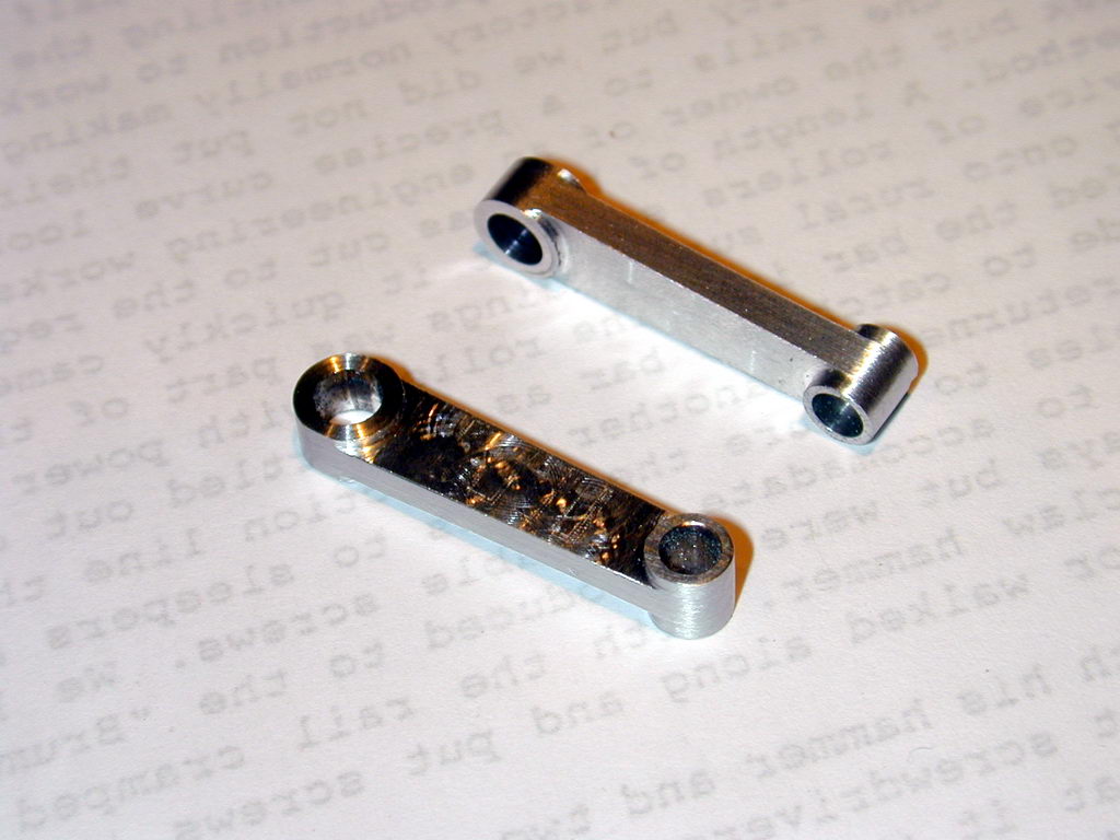
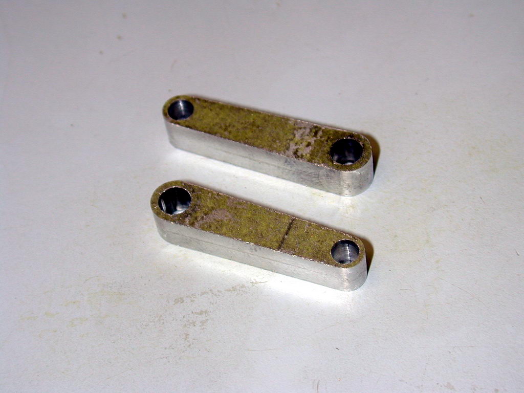 The ends of the rods are radiused using the method shamelessly stolen from observing how Taipan once made rods. This is fully described in the page on conrod making. The photo here shows a pair of rods fully profiled and ready for the next step. The green gunk is zinc chromate primer on my stock of ancient aircraft grade 2024-T3 plate, used to prevent corrosion.
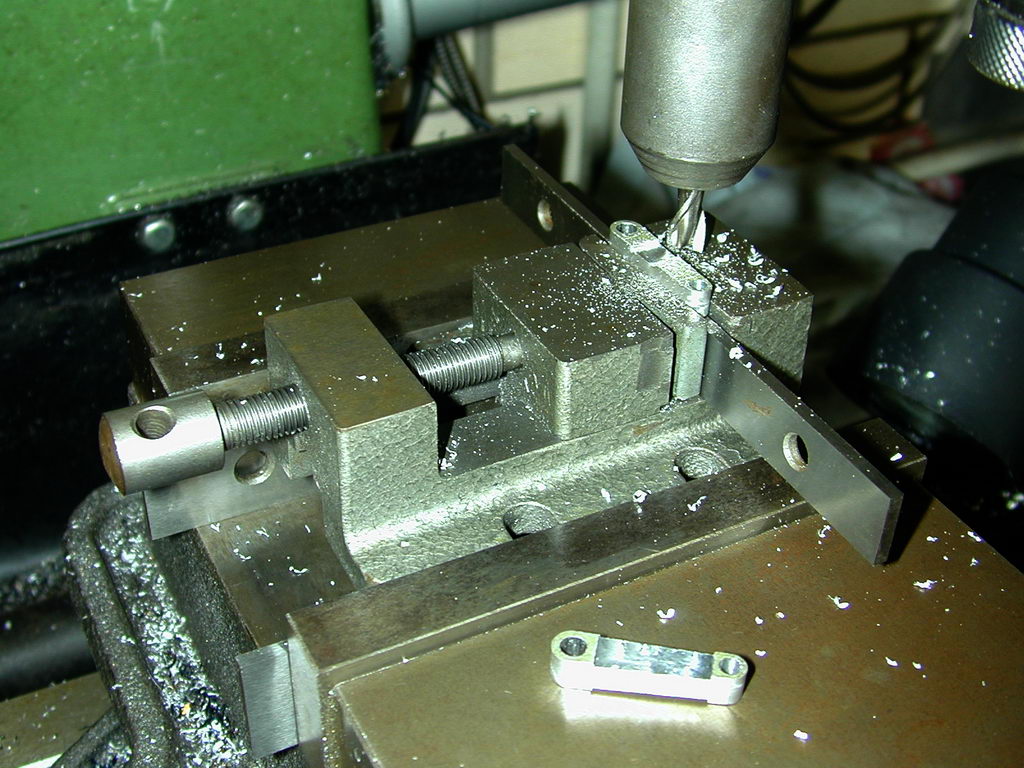 The next step is to thin the center of the rods to 1/8" thick. The photo shows an old Myford vise that has a "rocking jaw". This is clamped on parallels in the standard mill vise (I'm lazy) with the rod blank sat on yet another parallel. Locking the quill and flipping the rod ensures equal amounts are taken from both sides. Although the big-end needs to be reduced in thickness, this is not done now as that would make it hard to align the blank on the parallel after flipping over.
 For the last stage, the rod is wrung onto a tapered mandrel to complete the inner part of the end profile. Tapered mandrels don't taper over their whole length—the are accurate in diameter sufficient to support the part and have a tapered end onto which the part can be pushed to lock it in place for light work like this. This setup also allows the rod thickness of the big-end to be reduced neatly by 1/32" on each side.
Crankshaft
 The Sugden construction article suggested turning a three-jaw self-centering chuck into an offset turning fixture by assembling it so that the #3 jaw was a number of scroll turns behind the other two. This is similar to using a four-jaw independent chuck to offset the work, with a couple of key differences. When using a 4JC for offset to almost the work diameter (as we need for a crankshaft), two jaws grip across the work diameter, but the other two grip across a thin chord. It works, but it's not great (to my untrained mind). The 3JSC chuck may not have the jaws at 120° intervals in this case, but they do provide a better grip. On the down side, the 4JC can be set precisely to the offset needed. You will need to insert shims to achieve this using the reassembled 3JSC trick.
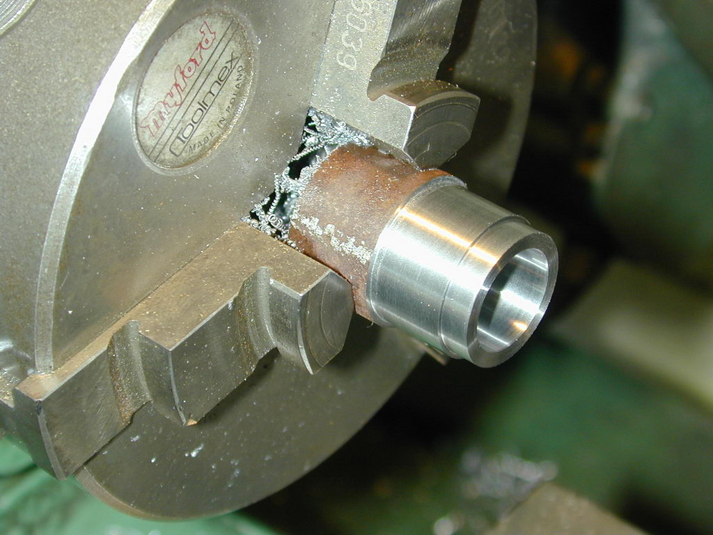
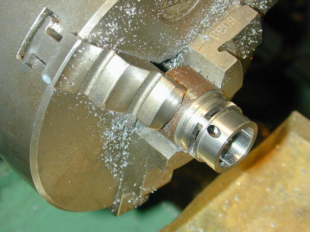
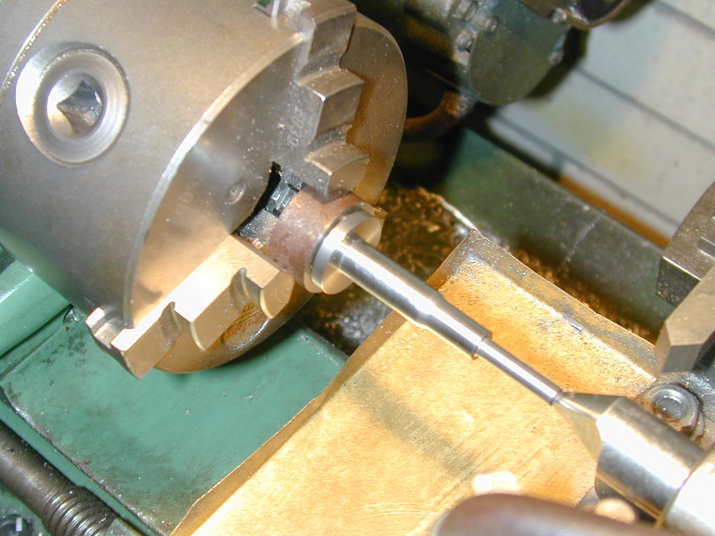
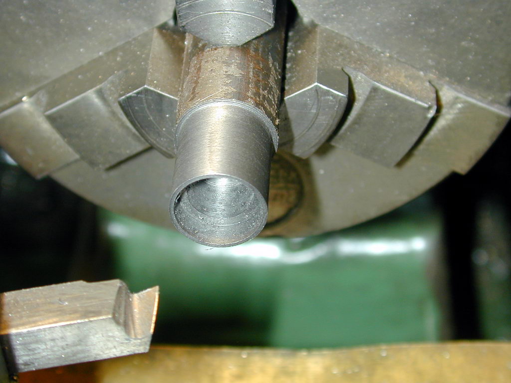
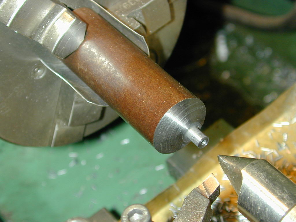 Work on the 7/8" blank starts by fully forming the crankpin. I used a small center to support the end because of the amount of overhang from the chuck jaws. The pin was formed over-length so most of this center could be turned away after the pin was finished. This all went well and painlessly.
 After making the simple carrier as detailed on the Crankshaft Making How-To page, the 3JSC is returned to normal and centers are drilled in both ends of the blank. Think about it. Maybe the axis of the crankpin ran true with the axis of the blank when the pin was turned. Maybe the two centers will actually be on the axis of the blank after it has been removed tightened etc (how good is your 3JSC?) and maybe the blank is clean and regular on the outside. Too many maybes. But then, how big do the errors need to be before we introduce unacceptable friction by having the two axes misaligned? Anyway, the pin will deflect at TDC, so some manufacturers actually introduce a compensating tilt on the pin. Maybe the error will be in the right direction. And maybe I worry too much...
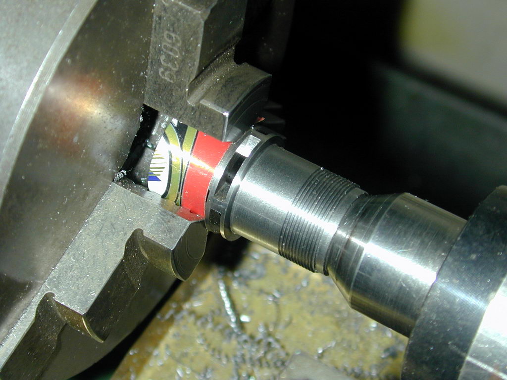
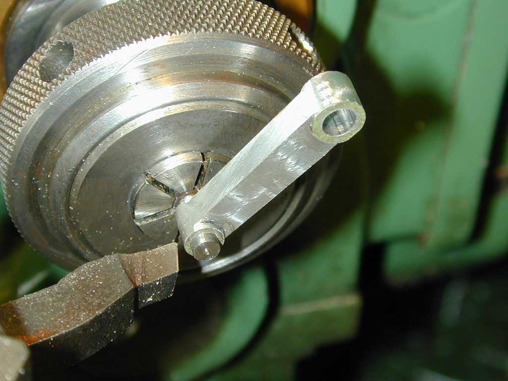
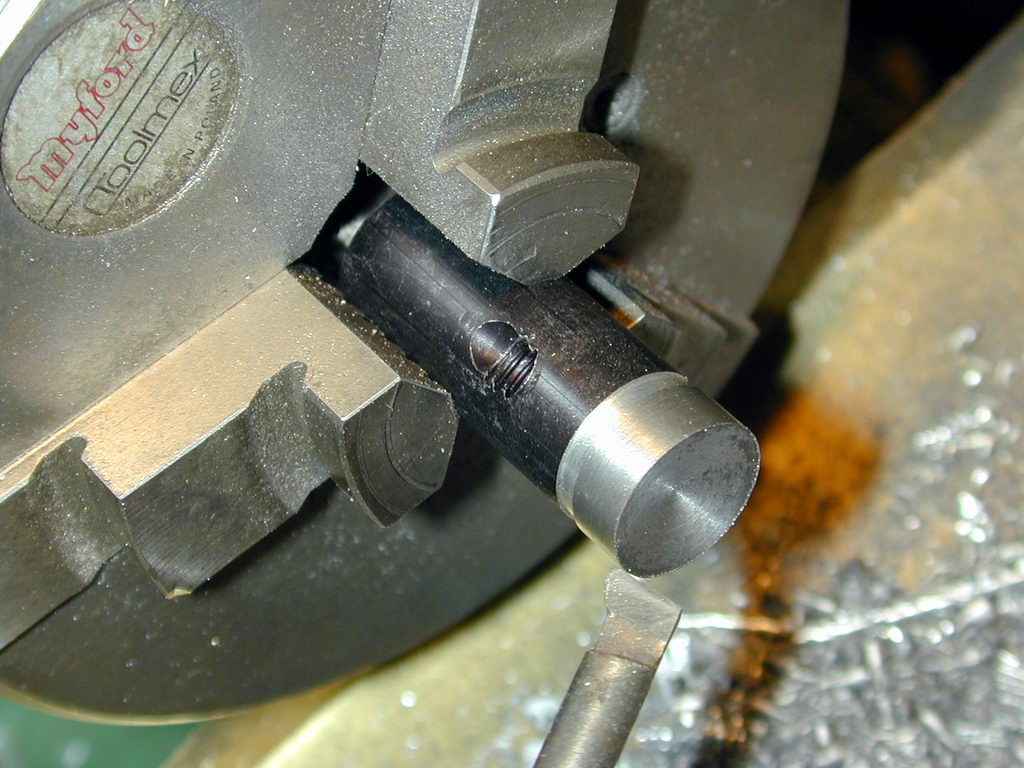
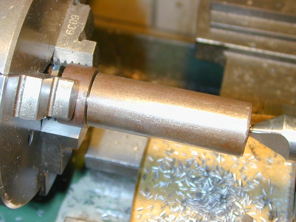 So the blank was center drilled and setup between centers, with a piece of drink can shim protecting the crankpin finish, as seen here. Normally I'd run heavy cuts (heavy for the Myford is 0.2" diameter reduction per pass), but in this case I went easy taking only 0.08" per pass. After all, there's no foreman clocking my productivity. This all went quite well and happily.
 As designed, the Sugden shaft has three concentric diameters: 3/8", 5/16", and 3/16". The two larger diameters must be a close running fit in the crankcase journals. This can only be tested by fully sliding the shaft into the case. Normally, a crankshaft would remain undisturbed in the 3JSC until the journal is finished. The fit being tested by pushing it into the case backwards because there is not enough protruding from the chuck jaws to do it any other way. Clearly this will not work with a stepped shaft like this one. So turning between centers—which allows the work to be easily removed for trial fit, then replaced with 100% repeatability—is the only way to go really.
Some final observations on the crankshaft:
This may all sound a bit Heath-Robinson, and would not serve for any kind of volume production. But for a one-off job, it will produce sufficiently accurate results. The venturi opening can now be used to establish the opening and closing points for the crankshaft inlet port as described above.
With the center located, the edge finder is used again to establish a reference for the piston skirt. The mill table can now be advanced .2656" (17/64) to position the gudgeon pin. The Sugden design uses brass pads on the end of a drilled out, fully floating wrist pin, so center drill, drill through 9/64", then ream through 5/32".
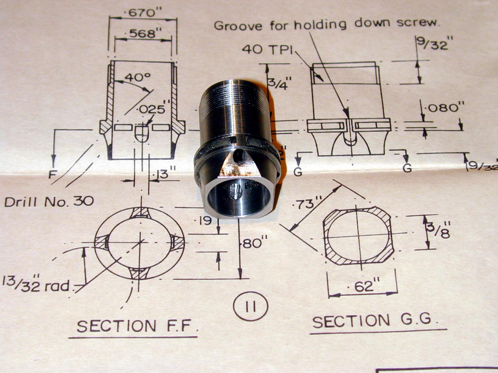
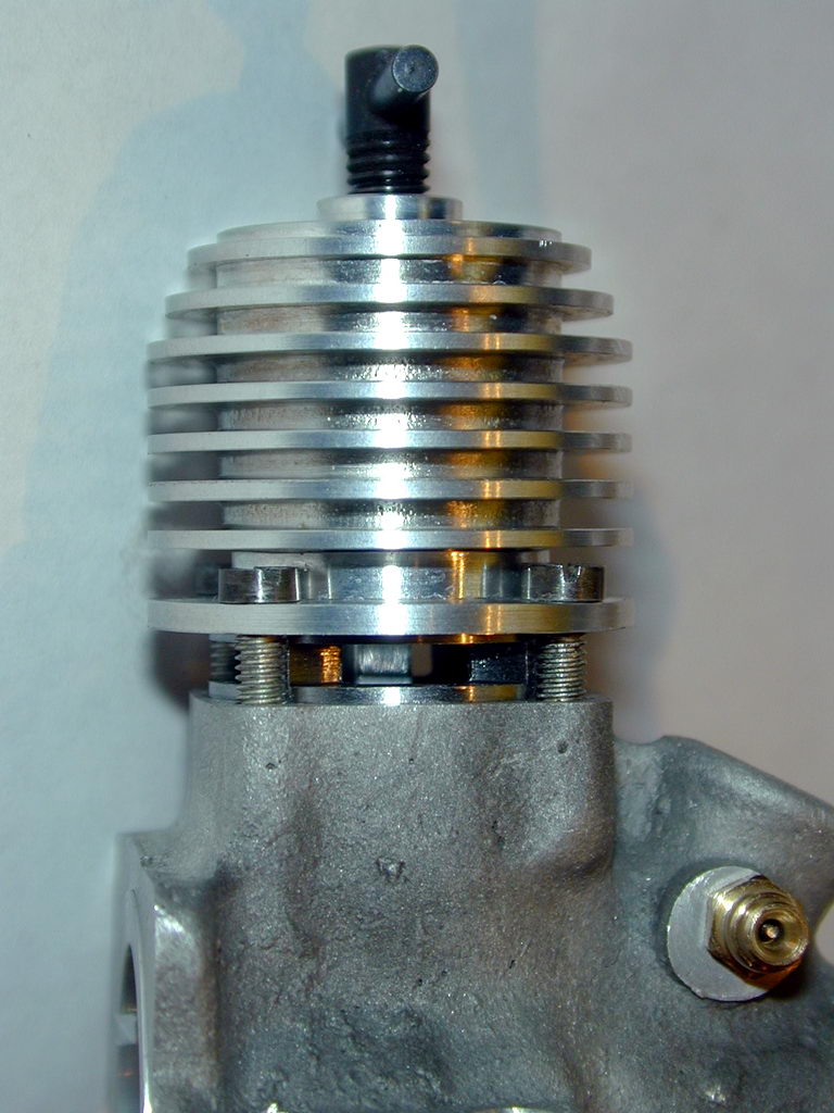
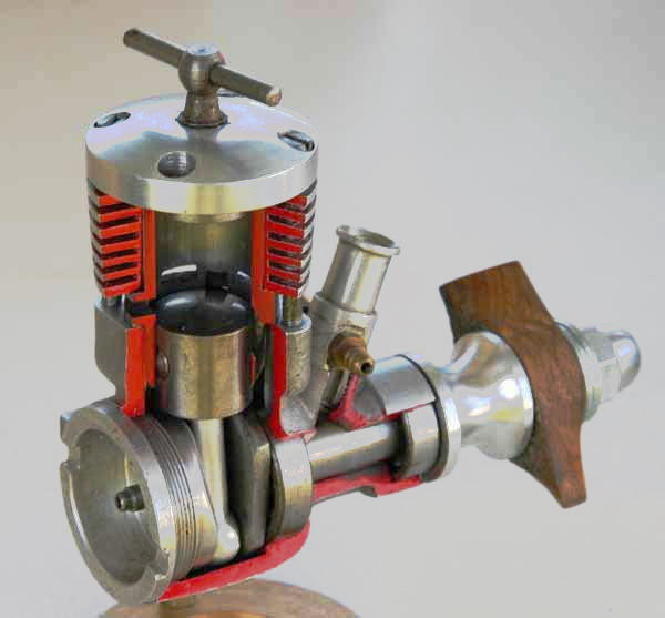
Dave Sugden pruned the excess metal in this engine down to the bone in search of the best possible power to weight ratio. Not only is the contra piston very short (13/64"), the 'run' position for it is very close to being flush with the top of the liner—as indicated by the short length of the compression screw. The result is no excess liner and cooling jacket above the contra, so parasitic weight is saved.
The Sugden is now returning 12K RPM on the 8x6. Looking down the cylinder with CP removed, the piston is uncovering only about 50% of the transfer ports at BDC. I'm quite confident I hit the deck height and conrod span right on the numbers, so I'll have to model the parts in CAD to see what the theoretical positions are. It looks like the liner could be raised by 0.010" or so and still have fully open exhaust at TDC. This would give extra exhaust and transfer duration. Time permitting, I'll also apply the ICE model to the figures and see what it predicts. But regardless, the world is richer to the tune of one genuine 1955 vintage, running Sugden Special (if we measure from the oldest part Ok, that's easy to verify. Make a new rod. Run the engine with the old rod to establish a figure with an APC 8x4, glass-filled nylon prop (so as to facilitate easy comparison with other Sugden builders). Change to the new rod, and re-test on the same fuel, under close to the same operating conditions—ie, perform the rod change-over quickly. I paused to record the distinctive carbon pattern on the piston crown that clearly shows the path taken by the exhaust and transfer gases. The results? Ok, I won't keep you is suspense any longer. Dave Owen's theory would appear to be correct:
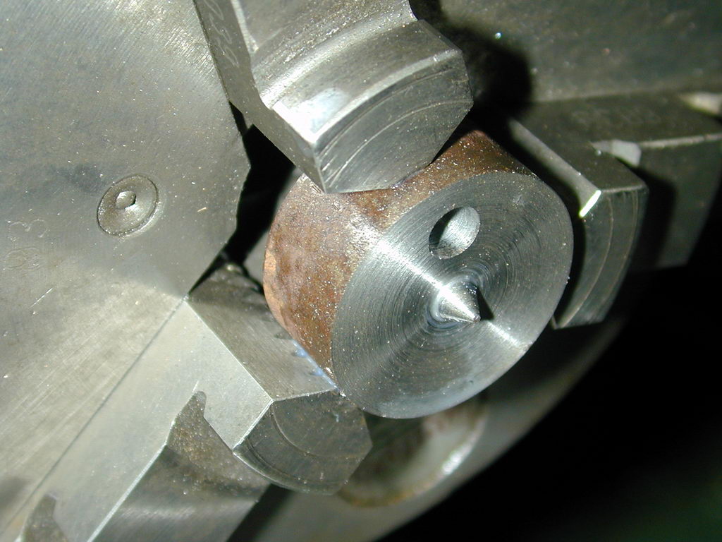
 The crankshaft counterbalance of the Sugden is similar to that of an Oliver Tiger (on which the engine is partially modelled). I performed a little CAD work to determine what drill shank to place under the pin to produce the correct angle for metal removal. The answer could also be derived from some basic trig calculations, or even using a cardboard cutout glued to the web face. To save you the trouble, the answer is #22.
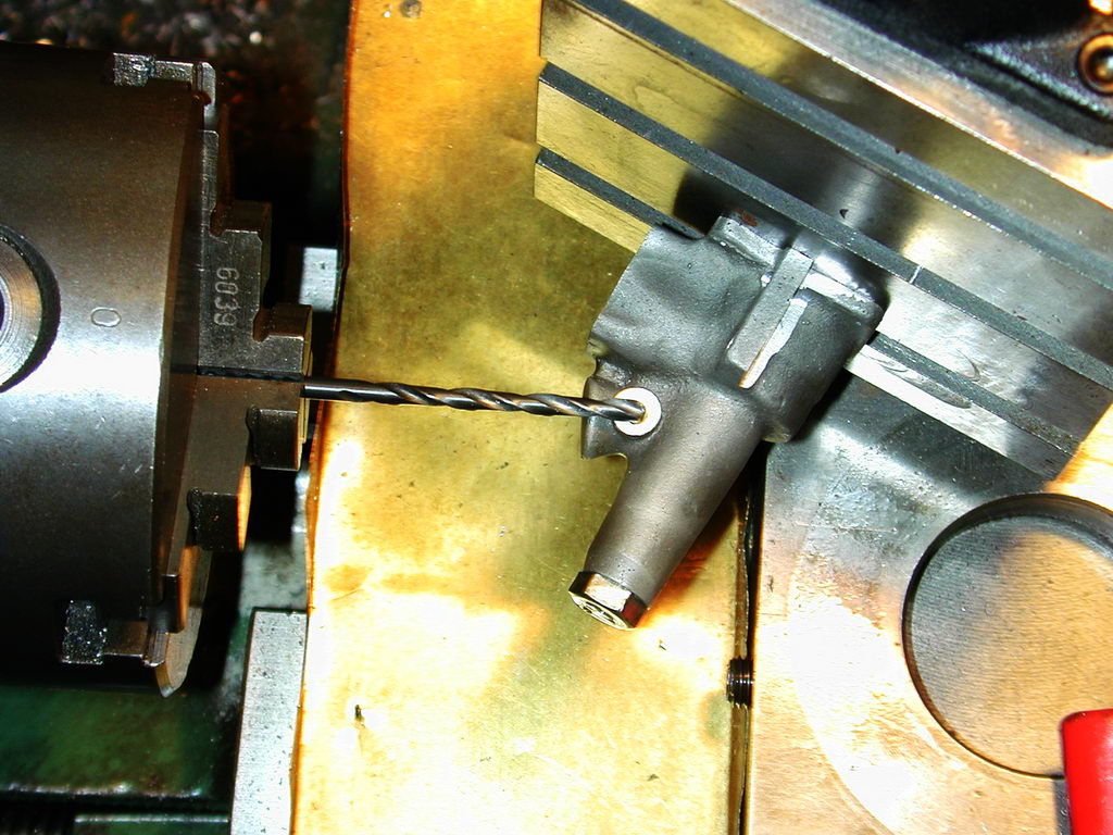
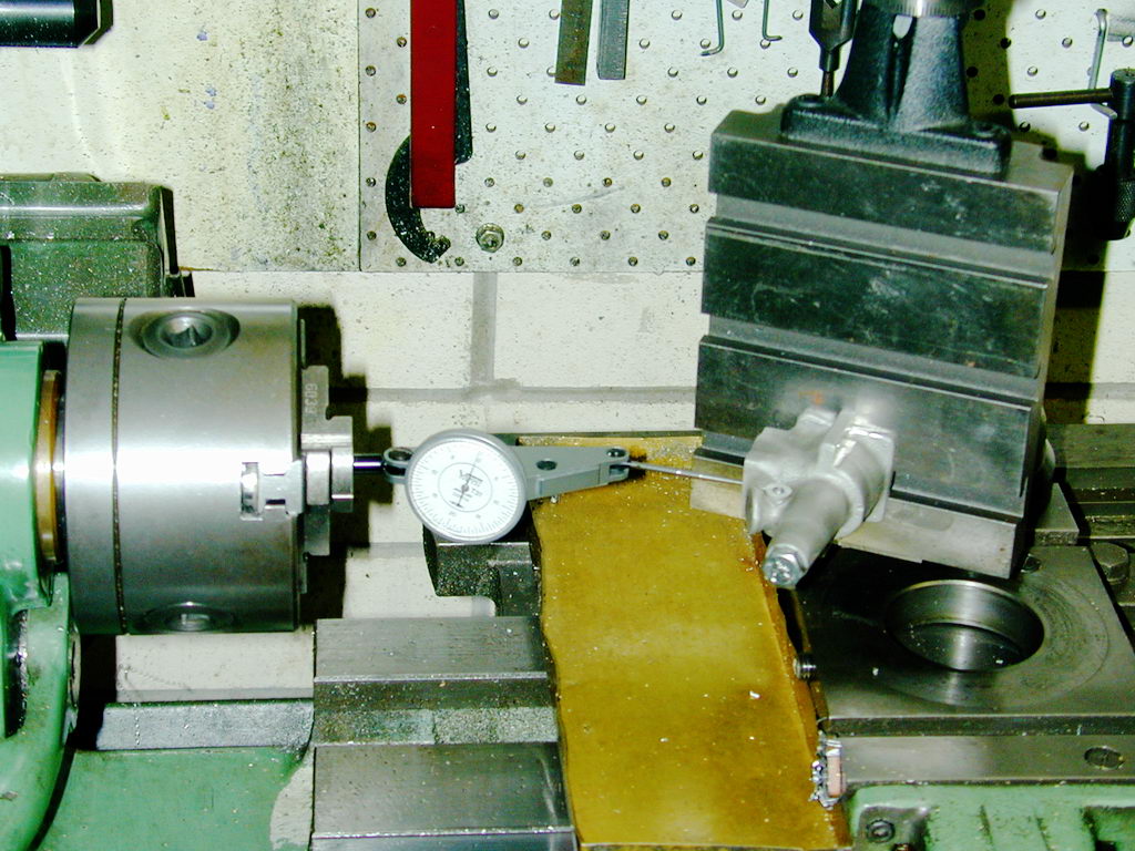
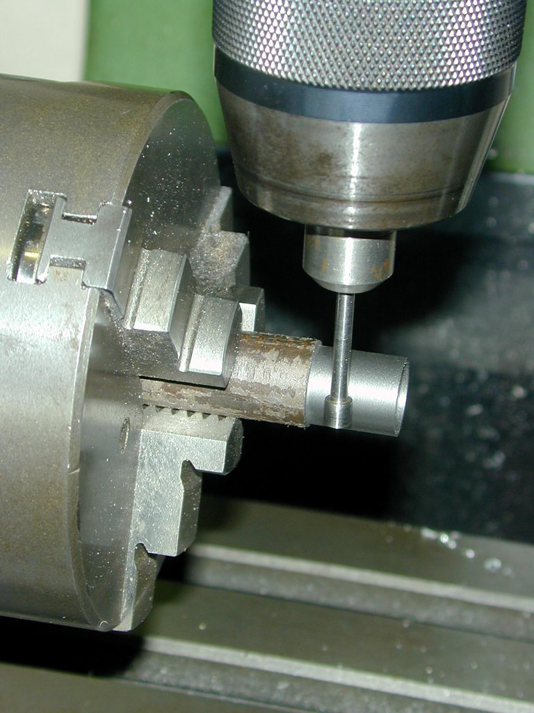
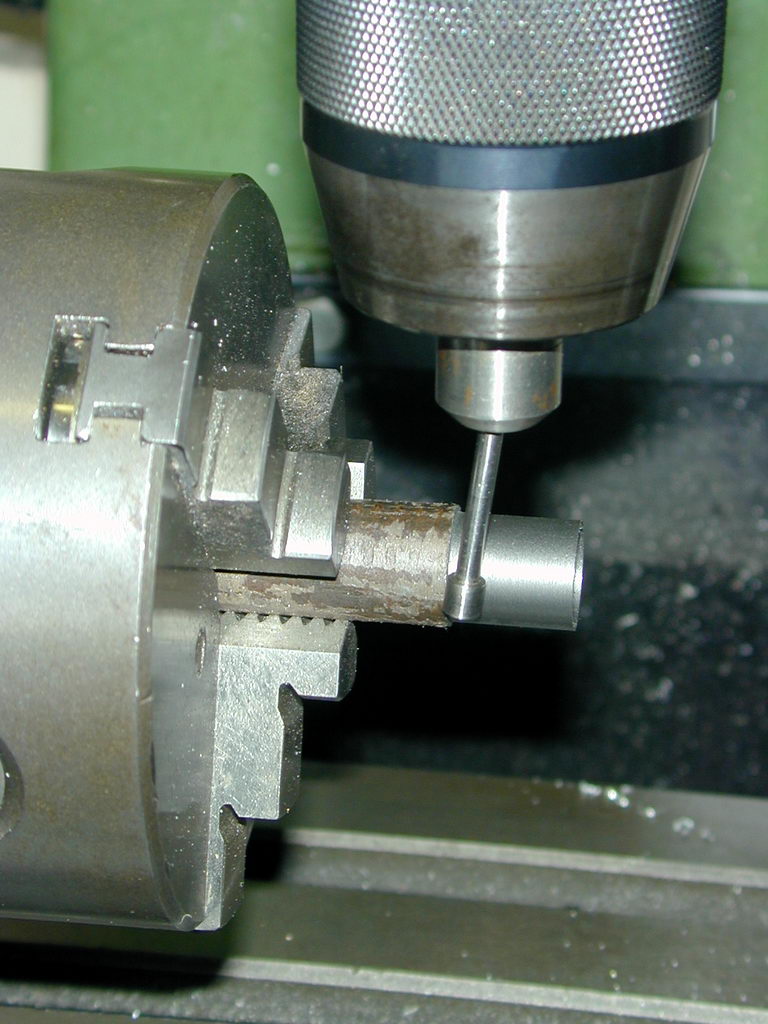
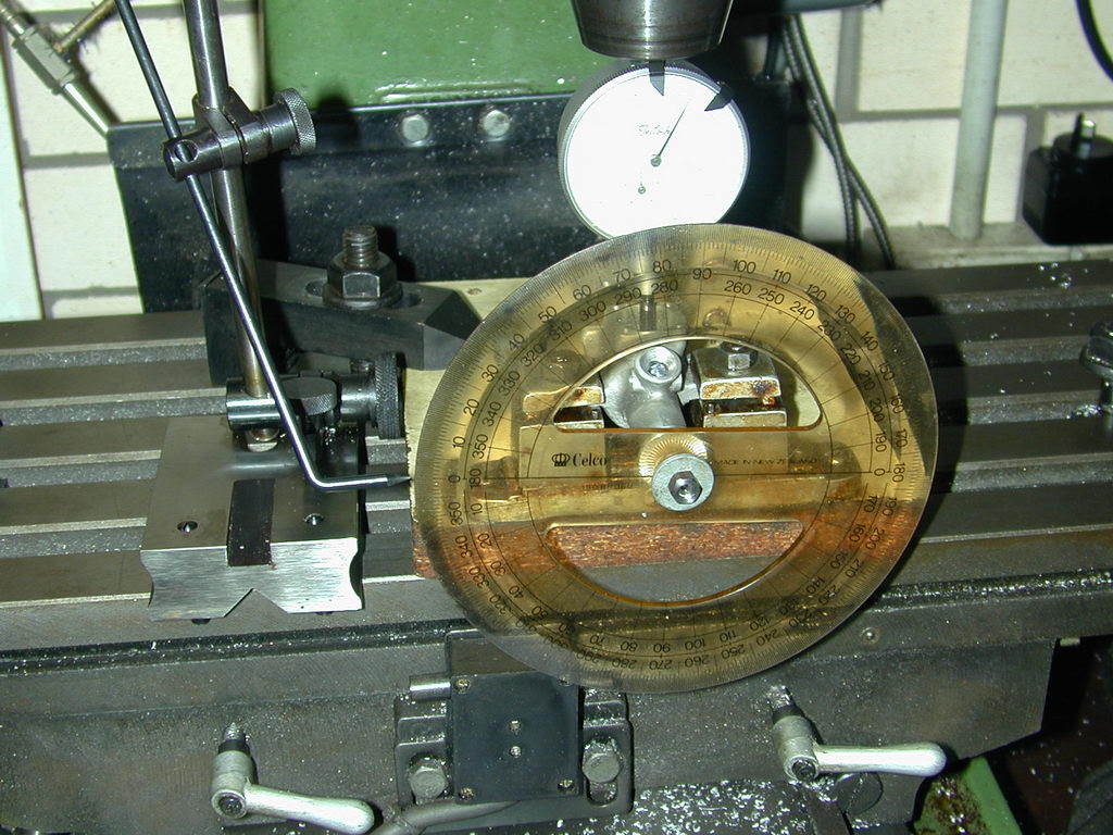 Many plan sets for front rotary valve (FRV) engines specify the inlet port location as being offset so may degrees from the crankpin radial. Not so for the Sugden. The plans simply say Open 55° ABDC; close 45° ATDC and leave how—and the opening shape—up to you. This method of designation is actually not a bad idea. The photo here shows the mark-out set-up. With a drawing protractor attached to the shaft as a degree wheel, a plunger DTI is used to find TDC. The scriber block is then adjusted to point at zero. The wheel is then turned and held to the nominated points and a fine scriber used to mark the shaft at the side edges of the venturi opening (the shaft having been "blued" before setting up).
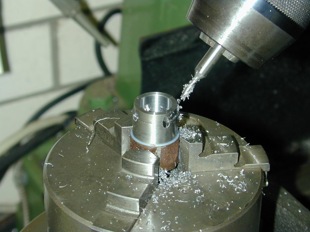
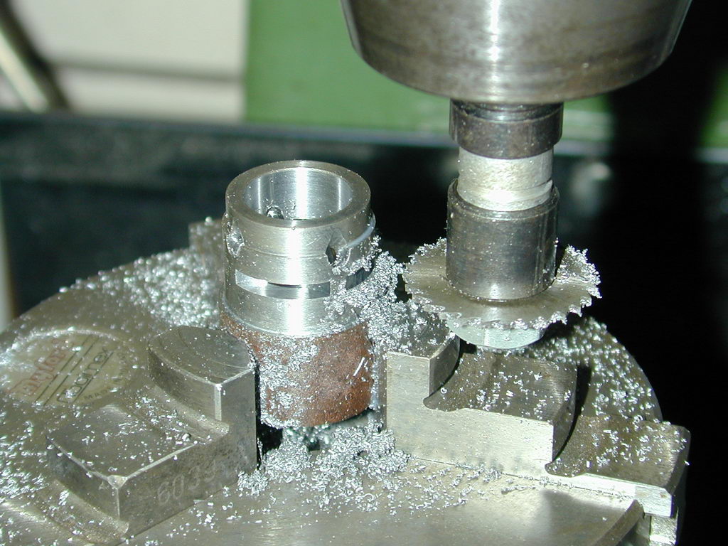
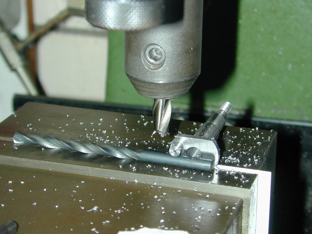
 The port edges are then lightly scribed along the shaft and new scratches made down the venturi opening to pick up the fore-aft port opening limits. This gives a rectangle for removal. This can be done in a V-block, or by gripping the crank web in the mill vise. Don't try to make a single transverse cut touch both opening extents. Angle the shaft so the cut can be made through one, exiting above the other. This allows both to be hit precisely. Then reposition so that the opening will be about vertical and mill out a square-ish opening with a 1/8" ball-end mill, as seen here.
Venturi
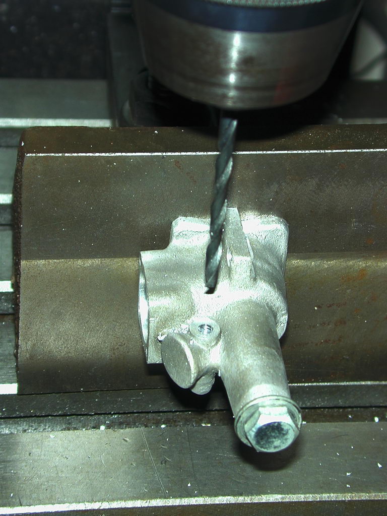
 I'll waste a few words on how I drilled the venturi holes, as a friend visited, looked at the raw case, and asked with some exasperation, "how the devil are you going to drill that out!?" This was an eye-opener to me as I did not view the operation as tricky in the least. The problem is to arrange things so that the venturi axis is on the same plane as the vertical crankshaft diameter, inclined at 25°, with the spraybar cross drilled to intersect it in the middle of the venturi inlet, a specific distance down from the top of the opening.
 Checking the bosses cast into the case for the spraybar showed they did not line up (no surprise given the roughness of the 1950's green sand casting used). I used "Jenny callipers" to locate the one that came closest to being in the right place with relation to the top of the venturi, then mounted the casting on an angle-plate to drill thru, normal to the cylinder axis, to clear a 4BA spray bar. As noted on the Sugden page, this is a deviation from the original design. This called for this hole to be tapped 4BA on one side, preventing the spray bar from being reversed for upright mounting in a control-line model where we want the inlet side to be on the "outside of the circle".
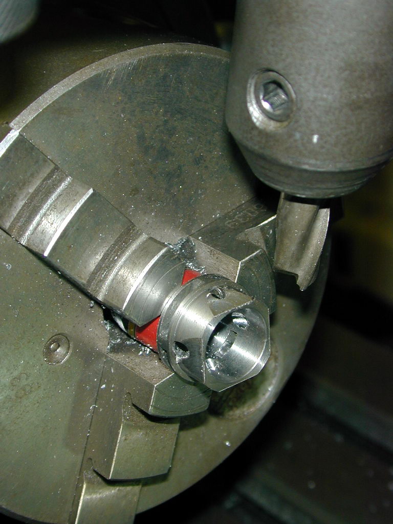
 The venturi is drilled in the lathe using another attachment that does not get much use these days: a Myford vertical slide. This was my only milling capability before I acquired the heap-of-rubbish mill/drill, and it is still occasionally useful for odd jobs like this. The case was trued up so that the cylinder axis was horizontal, then the slide was rotated so the venturi could be drilled at 25° to the cylinder bore. To make the spraybar and venturi axes intersect, the slide was lowered so that a pointer could be placed above the casting to neatly intersect the spraybar hole. In this picture, I'm using the same drill size that was used for the spraybar hole. At this point the cross slide was zeroed, taking note of the backlash direction.
 Having established the longitudinal position, the vertical position was found using a DTI to locate the center of the cylinder liner bore (which is centered over the crankshaft bore) by raising and lowering the vertical slide looking for a minimum reading. The vertical slide was then locked and the cross slide returned to the zero set earlier, being careful to get the backlash direction the same as previously. The venturi was then center drilled and pilot drilled through the bronze bushing. Final drilling was done with a 1/4" slot drill (two flute cutter). These are very rigid and so ensure that the tip does not wander as it breaks through obliquely into the shaft bushing. The venturi opening is finished with a counter sink tool to bell-mouth the inlet side.
Pistons
Making pistons in general is covered in depth in the How-To page for piston/cylinder material selection, but I took some shots that are worth commenting on. The Sugden piston has a conical crown. The contra-piston has a corresponding concavity. The theory is that the transfer charge will be deflected vertically up the cylinder by the slope of the crown, rather than blown out the exhaust port opposite the transfer port.
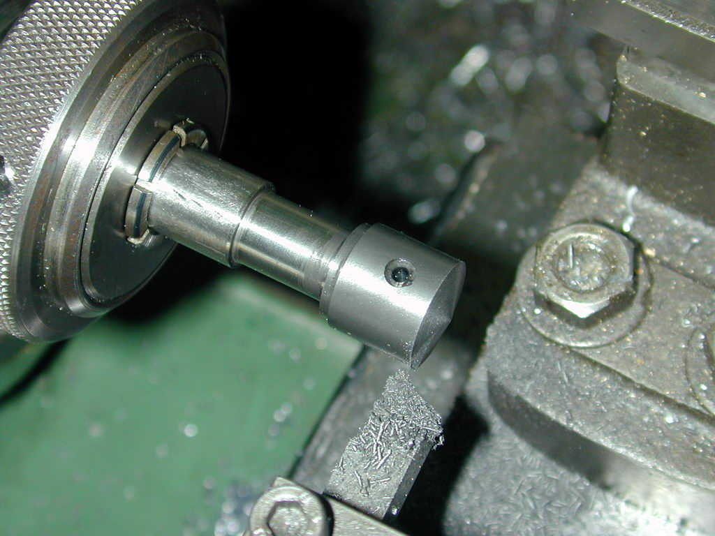
 The shot here shows a piston (I made two—don't ask) turned to about 0.001" larger than the lower opening of the liner. The blind, stepped bore is machined before the OD is finished. I drill and ream for the gudgeon pin (using the British term in deference to the design) before parting off as it is easy for me to transfer chuck and work to the rotary table under the mill. Which leads to the way I favour for centering round things for cross drilling.
 The device being used here is a shop made, GHT style edge-finder, as described in the GHT Workshop Manual. In the left hand shot, the finder is being spun at about 200 rpm with its side roughly centered on the diameter. The work is being very slowly wound out. The GHT finder probe has spring loaded ball on the inside end. While the work is greater that 1/2 the diameter of the tip away from the job, it is just being slowly knocked towards the vertical. But go a few tenths of a thou past center and it suddenly flicks out as seen in the right hand shot. Some math on the work diameter and indicator probe tip diameter then gives the dial setting relative to the axis of the job. Now repeat from the other side. If the dial was set correctly, it will flick at the same reading (provided you take up backlash correctly, or have a DRO fitted as I do).
 After the hole for the gudgeon pin has been drilled and reamed 5/32", the piston blank is parted off over-length and mounted on a fixture for finishing the crown and honing to fit the liner. The plans don't give a cone angle, merely saying that the height of the cone is to be 1/16". Some math (or CAD work) shows that the set-over angle required is 12.41°, but this is secondary. The important dimension is the distance from the gudgeon pin axis to the lip of the crown as this governs exhaust (and transfer) timing. So accurately scribe a mark 0.453" (29/64") from the bottom of this piston (assuming you've got the location of the pin reamed correctly). Set over about 12.5° and turn the cone until the scribe line is reached. If there is a slight flat top to the cone, or the piston looses a few thou of height, this does not matter; the lip location however does.
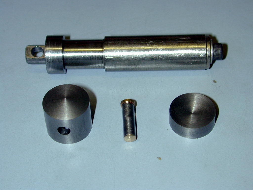 Here's the "universal" piston finishing mandrel, the Sugden piston, the part finished gudgeon pin, and the contra piston. The mandrel is turned from drill rod with two steps. I turn a collar to fit closely over the top step that is a another close fit inside the relief at the base of the piston. This centers the piston on the mandrel. A tapped, cross-drilled rod pulls the piston down onto the collar and mandrel. The hole in the draw-rod for the securing pin is purposely made a few thou oversize just in case the position of the hole in the piston is not precisely on the diameter as this would cause the piston to 'cant' as the draw-screw is tightened up. A wrist pin hole that's a bit off the precise center is not a disaster, but one that is not at 90° to the piston axis is very bad for friction.
 As the CP must have a conical relief to match the piston crown, this does not leave a lot of room to make a DCO type contra piston, but it can be done, barely. Mine was first counter-bored on the top side to a depth of 0.100" with an ID of 0.538". This will give a wall thickness of about 0.015" for the upper section. The CP was then pushed onto a temporary mandrel to turn the 0.5° DCO taper and polish so the thick end just enters the liner top. The concavity can then be turned to the same angle as the piston crown using a pointy boring tool as seen here.
Assembly and Test
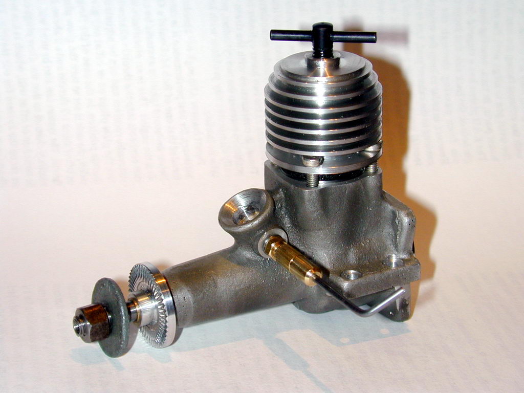
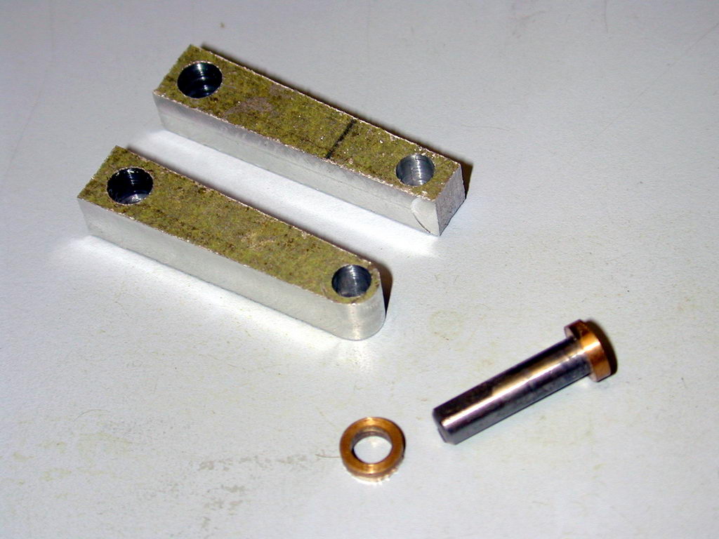
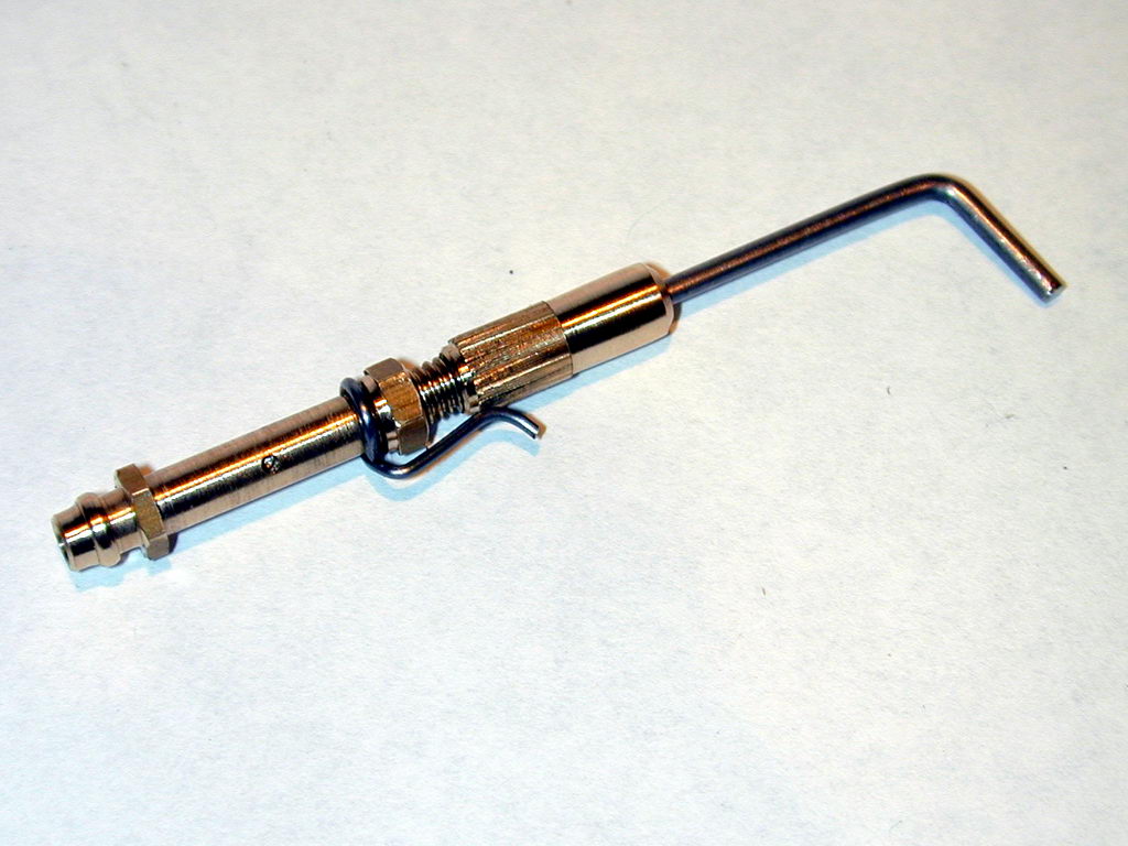
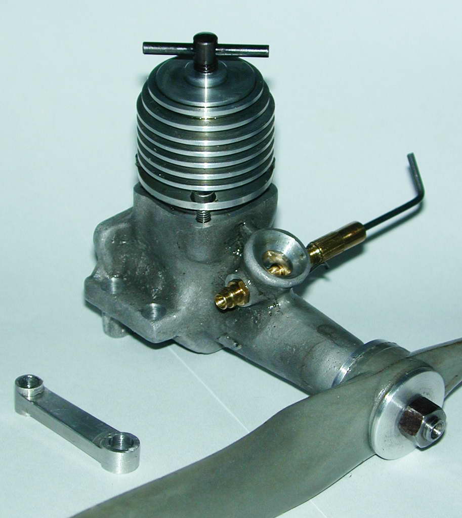
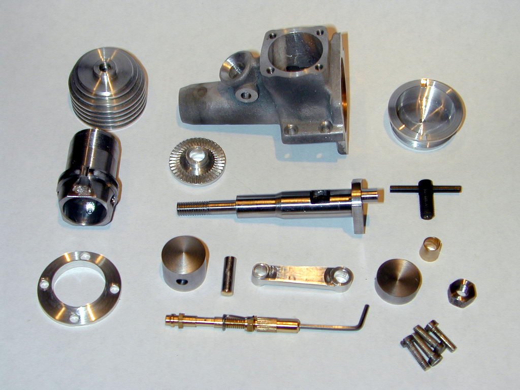 With the exception of a prop washer and the crankshaft bush which had to be fitted prior to drilling the venturi, this photo shows all the parts of the Sugden Special ready to assemble. The deviations from the plans are a comp screw 1/8" longer to account for the DCO type contra piston (the standard one is solid), a more conventional NVA with a needle seat, and a split cone for the prop drive washer. After careful cleaning in an ultrasonic bath, assembly is straight forward. The conrod fits easily over the crankpin (a frequent area of assembly difficulty) as there is a large space between the rear of the crankpin and the front of the backplate. The rod is prevented from riding backwards by the way its upper 1/4" thick boss takes up nearly all end-play on the gudgeon pin, keeping it central in the piston and hence on the crankpin. I'm assuming the low primary compression caused by the large crankcase volume was selected in pursuit of high power (less power loss on the down-stroke).
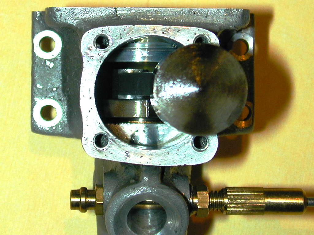
 The big surprise came when the engine was assembled and turned over for the first time. The piston completely opens the exhaust ports on the up-stroke! This is called "sub-piston induction" and is not that uncommon in high speed engines. But I don't think I've ever seen an engine that takes it to this extreme. The Sugden has more SPI than a deep-sea diver—the skirt of the piston actually rises above the exhaust slits. Looking at the photo, with the piston at TDC, all you see is conrod. The idea is the venturi area can be kept down to give good atomization through high inlet velocity and the crankcase vented to the atmosphere at TDC to try get some extra air in now that we have fuel.
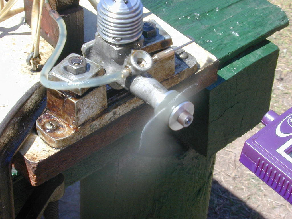 Testing so far has been limited, but is encouraging. First, the Sugden runs hot. Initial runs were made with a 9x4 Kavan nylon prop because I like a little extra flywheel effect while the engine is tight. With this prop, the compression had to be backed off after it warmed up to prevent it dying of over compression. The needle setting was also rather critical. All together, not a happy camper. After a tank or three had been run through it, the prop was changed down to an 8x6 APC and the nature of the engine changed. The needle sensitivity went away, as did the need to reduce the comp after starting. In fact, after a few more tanks, the engine could be hot-started without changing any settings; ideal for a team race engine where quick pit-stops and consistent running win races.
).
Testing so far has been limited, but is encouraging. First, the Sugden runs hot. Initial runs were made with a 9x4 Kavan nylon prop because I like a little extra flywheel effect while the engine is tight. With this prop, the compression had to be backed off after it warmed up to prevent it dying of over compression. The needle setting was also rather critical. All together, not a happy camper. After a tank or three had been run through it, the prop was changed down to an 8x6 APC and the nature of the engine changed. The needle sensitivity went away, as did the need to reduce the comp after starting. In fact, after a few more tanks, the engine could be hot-started without changing any settings; ideal for a team race engine where quick pit-stops and consistent running win races.
).
Modification and Re-Test
 Some six months after the above paragraph was published, the question of raise the moat, or lower the drawbridge popped up again. Motor Boy Vincent Chai, getting ready to machine his own Sugden die cast case, re-raised the very good question of just why does the Sudgen Special have so much sub-piston induction? The piston skirt actually moves above the top of the exhaust port at TDC. The the sub-piston induction period even extends beyond the inlet close event! David Owen was called into the picture and he quickly came to the conclusion that the very high SPI may be due to a drafting error. His reasoning ran thus:
| Rod BC | RPM cold | RPM hot |
| 1.050" | 13,200 | 12,800 |
| 1.000" | 14,600 | 14,400 |
That's a 12.5% increase in hot RPM—significant in anyone's books. Naturally, the fuel consumption increased (as one would expect when the engine is doing more work). The pitch of prop used is less than the Aeromodeller test figure, and we'd have to think that an APC GFN prop is more efficient than a 1955 Frog nylon paint-stirrer, but remember that the Aermodeller test report did note the fuel used was heavily nitrated. Mine was straight 1:1:1 with no additives.
So the question remains: are the plans "wrong", or was the short exhaust period a specific design parameter aimed at trading off power for fuel consumption? Remember, the Sugden Special was intended for use in Team Racing where pit-stops can and do win or loose the race, so outright speed will not always win.
About this time (May, 2006), we tracked down Dave Sugden, now a retired dental surgeon in Canada and frequent member of Canada's world FAI free-flight competition team in years past. He was rather amused that his old engine design was receiving all this attention after so much time, and was able to confirm that there was no mistake in the published plan regarding the conrod length, adding that they really did not know an awful lot about design way back then. So, based on a statistically invalid sample of one, our recommendation is:
- Reduce the conrod BC distance to 1.000"
- Increase the length of the cylinder liner below to flange to 11/32"
- Increase the thickness of the rod to 0.156"
- Increase the height of the contrapiston by 0.050"
- Stand back and cover your ears!
