How To Machine Crankshafts
Updated: Oct 29, 2010
![]()
There are probably more ways of holding an overhung crankshaft to machine the crankpin than there are of inducing involuntary discorporation in cats. Trying to cover them all at once would be a daunting task, so until I feel blessed with excess time and energy, this technique page will constrain itself to the most common sort of shaft a home-shop builder is likely to make: the overhung, single throw shaft, machined from a solid bar. Discussing this topic with The Motor Boys, we concluded that each of us had a favourite technique and all were different in some way, frequently being governed by the different types of equipment we each have, and the content of our respective scrap boxes. Each has merits, and all work. Naturally, I prefer the way I do it, but that has changed 4 times over the years, and may change again. So use this page as a grab-bag of ideas and see what will work for you.
 Turning the Main Journal
Turning the Crankpin
Bert's Variation
Crankshaft Balancing
ETW on Crankshaft Balancing
Turning the Main Journal
Turning the Crankpin
Bert's Variation
Crankshaft Balancing
ETW on Crankshaft Balancing
![]()
Turning the Main Journal
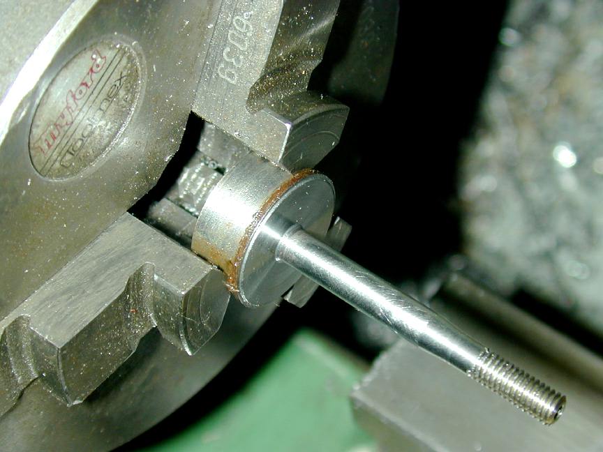
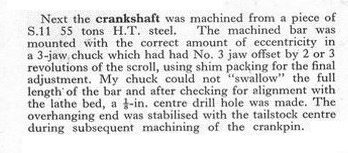
I've read (and used) a number of approaches to producing an overhung 'shaft. That provided by Westbury in his book, Building the Atom Minor Mk III must rank up there with the most time consuming, but "correct" way, involving meticulous marking out, center drilling on opposing blank faces, followed by (in order), turning the crankpin, then the main journal. I actually followed this on my Atom Minor and produced a useless shaft owing to a misreading of the drawing that gave it more throw than there was head room to accommodate. Never again. What this really convinced me of was that I hate marking out! I've long since evolved a process based partially on the sequence described by David Owen in his well thought-out instructions for machining the DIY Mate 2cc Diesel that obviates the need for any marking out whatsoever!First a word on the front section of the shaft—the bit that will carry the prop. Most amateur built engines will be produced from steel and left in the soft condition. Heat-treating causes distortion, requiring that the shaft be finished oversize, then ground to final size and alignment. For 'soft' shafts, the best choice of material is "stressproof" steel, if you can get it. This machines ok with sharp tooling. Good old 12L14 makes machining the shaft a joy, but it's a bit soft, especially for larger engines.
Now since the shaft will be left soft, it is vulnerable to crash damage—generally in the form of a bend at the point where the shaft emerges from the front bearing and reduces in diameter, where the shaft is at it's most vulnerable. I've found that if the diameter here is 3/16" or above, it has acceptable strength. If it's smaller, even stressproof will be a bit on the weak side, so for smaller shafts, I strongly advocate drilling the shaft for a screw-in stud made from a cut-off cap ead screw, or even using a high-tensile bolt if you wish. Many commercial engines used this feature, and for exactly the same reason: it's easier to replace a bent stud than straighten a bent shaft!
Now, onto the markout-less shaft. Cut a blank that is about 1/32" to 1/16" longer than the overall shaft length. Pop in the 3 jaw self-centering chuck (3JSC) and face the ends with a minimal cut. Center drill the second face, then extend the shaft blank so sufficient protrudes from the chuck to form the main journal. With the chuck jaws only lightly tightened, bring up a dead center in the tailstock to align the blank, then tighten the chuck firmly. All chucks have run-out, especially 3 jaw self-centering ones. But even if the 3JSC is not 100% aligned with the axis, the final journal will still be formed correctly provided we don't disturb things as the finishing cuts are made. It's the unmachined web portion that will be out and we can fix that later.
First cuts will be deep ones to remove lots of metal, so angle the tool towards the tailstock so that if it deflects backwards, the depth of cut becomes shallower, not deeper. This will guard against a "positive feedback" situation where a dig-in becomes quickly self-perpetuating. You won't be able to get onto the corner of the web from this setup, but that can be fixed later. Reduce to within 50 thou of the journal size, then reset the tool to cleanup near the web and get ready for the finishing cuts.
I like to arrange my finishing cuts to be three or more passes at no more than .005 deep (0.010" of diameter). The final one I like to be only 2 or 3 thou deep to leave the shaft at 0.0005" to no more than 0.001" above the reamed bush size. Since the shaft actually needs to be less than this size, we have enough metal left for finishing. For this, I use a shop made hone that is a copy of an old Sunnen design. Alas, the source of the casting used for this tool is no longer in business. Alternates are to use a split donut with diamond lapping paste smeared on the inside, or even a piece of 600 grit paper backed up a flat steel ruler and lots of oil. Even though your shaft may look smooth after the finishing cut, it's really a very fine screw and the microscopic helical ridge needs to be removed. Hone and polish until it is a good running fit in the bush—experience will guide you.
If the shaft is to have a threaded, reduced diameter section, turn and finish (but don't thread) this before finishing the main journal. Threading is done last as we need to remove the center for this operation. Regarding centers, I believe "live" (revolving) centers are too inaccurate for finish turning shafts. You can use one while hogging the blank down, but change to a "1/2 dead-center" for finishing. The cut-out in this type of center lets you get the tool tip onto the work as it get smaller.
The diameter of the crank web should now be turned to be concentric with the main journal. Just how concentric depends on how you will form the crankpin. If you've left enough protruding from the jaws, good—do it at the same setup. If not, gripping the shaft on the journal in a collet will be fine and produce very accurate results, provided you have an appropriate collet. In desperation, the shaft can be lightly gripped in the 3JSC with a shim of drink-can aluminium used to protect the finish. This can produce a few thou of eccentricity depending on the state of your chuck. Purists might grip in the 4 jaw independent chuck (4JIC) and clock a short, protruding section of journal true. However if you use the offset jigs described below, a thou or two of eccentricity between the web and journal will not matter at all.
Turning the Crankpin
For this process, a special jig or fixture is required. I've seen some rather bizarre designs appear in magazines for this—not to say that they were impractical, just unusual—I'm sure their designers loved them! However all are designed to do the same basic thing: hold the turned, finished shaft journal parallel to the lathe axis, but offset from it so that the crankpin, when finished, will be perfectly aligned at precisely parallel to the main journal axis.As an aside, some designs, especially ones intended for high performance, don't align these axes parallel! This is because the crank pin on the web of an overhung crank will deflect varying amounts depending on the pressure being exerted on it by the conrod. At the point where the greatest pressure is being exerted, deflection will be greatest, so when the pin goes out of parallel, friction will be maximum. By biasing the pin, designers try to reduce this friction during the power stroke, accepting that friction will be higher when the pin is under less load, but hoping for an overall gain nevertheless. Knowing you've been successful at this game requires some rather sophisticated measuring equipment, and manufacture of several cranks (preferably run in more than one case to account for manufacturing tolerances). We'll aim simply to get the pin as parallel as possible to the crank's axis.
The Keats Plate Fixture
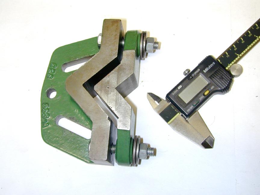 Here's a fixture known as the "Keats Plate" (or angle plate"). I believe the name originates with the English company that first released it as a commercial, catalogue item. It's use should be obvious: the main body is bolted to the lathe faceplate and the shaft clamped into the longitudinal 'V' by the smaller clamp plate. If a centerpunch mark has been made in the face of the end of the blank, offset from the center by precisely one-half the throw required, the Keats plate can adjusted on the faceplate so this mark runs true, and the pin turned.
The plate shown here (with a standard 12" digital calliper shown for size comparison) sits proudly on my shadow board and is almost never used. It was machined (by yours truly) from a set of iron castings imported from England at great expense. What I found is:
- It's a bit large for small cranks, and the clamping 'V' plate can damage the shaft finish if tightened to the point where you are absolutely sure that the shaft is not going to move during an interrupted cut.
- Conversely, for larger shafts, the V can be on the short side (longitudinally), meaning there can be an alarming length of unsupported shaft overhanging the fixture. Add an interrupted cut to this and the potential for permanent deformation exists.
- Finally, there's the problem of arriving at a combination of Keats plate slots and faceplate slots that result in the correct throw.
My final conclusion is that the poor old Keats fixture is 90% useless for the purpose which I made it. It occasionally is the perfect solution (the central shaft section of the Taplin Twin leaps to mind), but overall, there are better, cheaper, more effective ways of doing the job.
Using the 4 Jaw Chuck
We all know that the 4-Jaw chuck is capable of holding stock at any position in relation to the lathe axis within its capacity, so why not use it? Two problems. First is the tendency of the jaws to mark the surface of material being gripped. The impact forces encountered while forming the crankpin due to the interrupted cut are quite high, so the shaft needs to be held very securely. By the time we get to the crankpin, the journal has generally been finish turned and honed, so the possibility that the chuck jaws will damage the surface is high. Second, as the distance away from the center increases—say under the influence of the #1 and 3 jaws, then jaws #2 and 4 move progressively "off center". When the throw is large compared to the journal radius, we can end up with the #2 and 4 jaws not touching the work at all and consequently leaving our shaft virtually unconstrained in one axis.
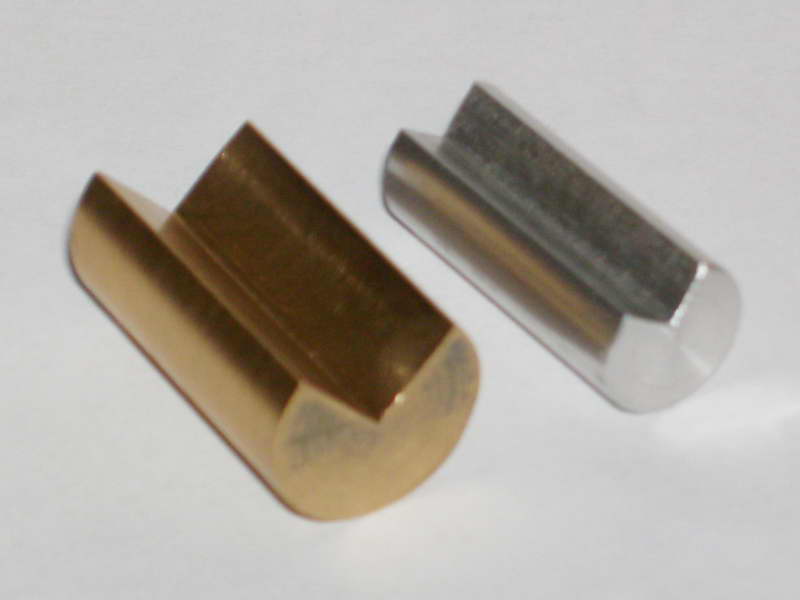
Jim Frew (UK) came up with the answer to this: a set of small V-blocks which effectively provide three-point clamping of the journal (one jaw and two sides of the V), while providing a good, close to center surface for our #2 and 4 jaws to clamp on, thus ensuring the shaft is completely constrained in both axis. Unless you are extremely heavy handed with the chuck key, a thin shim of thin brass or aluminium between the shaft journal and the naked jaw is enough to protect the shaft from clamping pressure damage. Jim's jigs seen here are round, but they could just as easily be made from square stock. The V needs to be very accurate in respect to the "axis" of the block, but that is not hard to achieve given a good set-up in the mill using a slot-drill (2 or 3 flute cutter) to produce both V faces simultaneously.
So after mounting up, you can either center on a marked center-pop on the end of the blank using a wobbler and DTI, or just clock the blank end of the shaft to achieve the desired throw. All you need are a set of blocks sized so that at the required offset, the #2 and 4 jaws fall reasonably centered on the jig block if round (if a square block is used, this becomes far less critical). Simple, and close to a universal solution. The only downsides are the need for precision in manufacture of the V block and the lack of positive constraint against the crank rotating under the pressure of an over-ambitious interrupted cut.
The Offset Jig
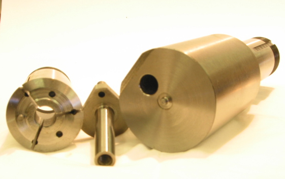
This is a popular and simple jig. A stub of steel (or aluminium, or brass even) is held in the 4JIC so that it is rotating eccentrically by an amount equal to the throw required. The jig is then drilled and reamered to the size of the crank journal. If you wish, the reaming step can be omitted as we don't need a polished finish as the shaft does not rotate in it (hopefully!). However care is required when drilling as the final result will depend on the hole being axial with the jig. If the drill wanders, the shaft will not be held in a line parallel to the lathe axis.After drilling, one of a number of schemes are implemented to hold the shaft in the jig. These are described below and you can take your pick. In use the jig is simply gripped in the 3JSC, automatically offsetting the blank end of the shaft for turning the pin. As we'll see later, Bert Streigler has an innovative alternate that complicates use, but makes the jig "universal", rather than requiring one for each shaft diameter and throw combination.
Once the shaft is gripped, the pin is turned. Always have the conrod on hand before doing this unless you are a master machinist able to make pins to a running fit in a hole that does not exist yet (in which case, you will not be reading this drivel!) There are two basic ways to form the pin: making a number of longitudinal passes, or making an even bigger number of radial passes, followed by some longitudinal finishing passes. The former allows more metal removal, but results in an "interrupted cut" that is hard on tool, tooling, and your nerves. I prefer to make radial passes, removing ten to fifteen thou per pass, stopping when the tool just starts to make a fully circular cut. Yes, this is an interrupted cut too, but somehow it seems kinder on the tool and the nerves. Stop making passes when you are within ten thou of the web, then start making fine, longitudinal passes until the theoretical diameter of the conrod big end is reached. The last pass can be used to 'face' the web.
The crankpin to conrod fit needs to be free, and to allow enough clearance for an oil film. The pin is polished using the traditional 600 grip wet 'n dry, backed up by a steel rule, and plenty of oil. Polish until the (cleaned) pin runs smoothly in the big end without any tightness. By the way, the tool used to finish turn the pin needs a small nose radius (or chamfer) so that there is no stress-inducing sharp transition to the web. Naturally, the conrod needs to be chamfered to accommodate this radius.
Now we'll examine the ways of securely holding the crank in the jig.
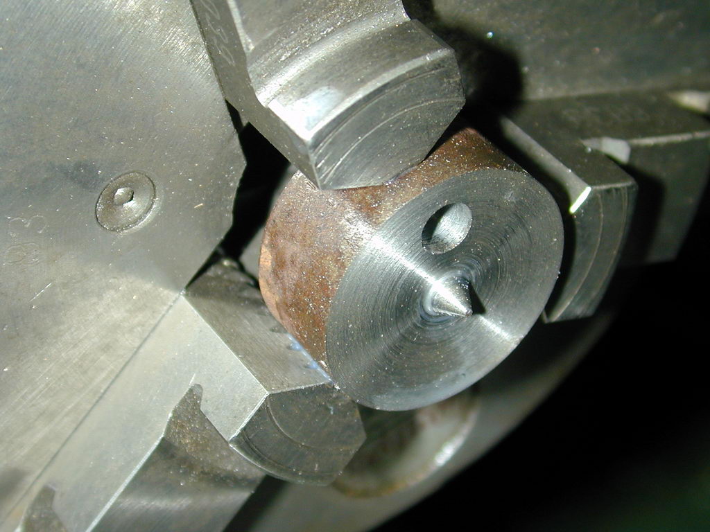
The Grub Screw Method
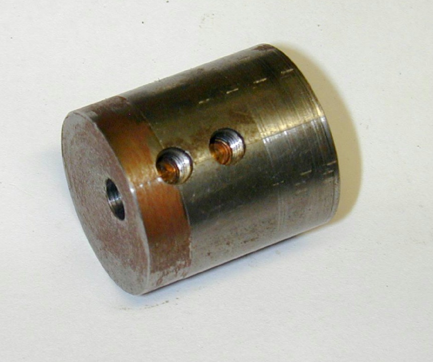 I've always call it the "grub screw", but really, it could use cap head screws, or hex heads come to that (Aside: US readers will most likely know "grub" screws as "set" screws. These are headless screws that can totally enter a tapped hole—hence the 'grub' connection that seems to have come out of England and taken firm root in Australia and New Zealand. End of aside). Two holes are drilled to radially intersect the hole for the shaft in the jig. These are then tapped for two screws that will, when tightened, hold the shaft in place in the jig. To prevent the tips of the screws from marking the shaft, two plugs of copper are turned to just less than the minor diameter of the thread. The shaft is inserted and the pads dropped into the holes. When screws are tightened over the pads, thew will expand slightly and the thread will bite into them, holding them in place when the shaft is later removed. In the Jig seen here, the screws have been taken out so that the slugs are visible (Grubs? Slugs? Sounds like a can of worms to me).
I've never really liked this method. It takes a fair amount of effort to drill and tap the holes, make the copper slugs etc. And the pressure they exert on the shaft is marginal at best when holding it against shifting under the interrupted cut. This method really requires insurance in the form of a pin that engages in the hole (or slot) in the crankweb. I've seen commercial cranks with a little slot in the rim of the web which must have engaged an anti-rotation pin. Others have a hole drilled thru the crank pin. As well as assisting static balance, this is another good locaton for the anti-rotation pin.
On the plus side, because the shaft can be inserted without removing or upsetting the jig in the chuck, it does lend itself to production use of sorts, and allows the hole to be drilled centrally in the jig and offset in the 4JIC using a wobbler in the hole itself. But I'm lazy; if I can avoid that pin and the hole that must line up with it, I will, and do!
The Split Jig
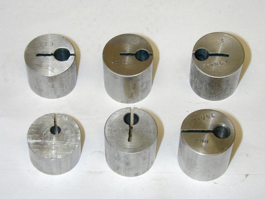 You can let the chuck supply the clamping force by simply sawing partway through the jig, then arranging for the cut to fall half-way between a pair of jaws when tightening up. All the little jigs seen here do that. The clamping force is now distributed over more area, when compared to the two little copper pads described earlier. For small shafts, I've found this is sufficient to prevent unwanted shifting, if you are careful and make relatively fine cuts. Note too that the jigs have been stamped (in most cases) with what they are for. I may never make another, but if I do, at least I'll know hat jig to use!
Referring to the photo above, you will see some variation in the position of the saw cut. After some experimentation, I conclude that the orientation shown is the bottom right (for the ML Midge in the optimum for best clamping—a fact that would be instantly obvious to Blind Freddy and his dog, but it took me a while never the less...
The Simplest Jig Of All
 And lastly we come to my currently preferred jig: once the hole is drilled, we're done—how simple can it get! The jig length is such that the propnut (and a washer, naturally) can be used to draw the shaft very firmly into the jig. For smaller shafts, a cap head screw into the threaded hole for the stud does the same job. This I've found, provides adequate clamping strength to prevent shaft rotation.
If you are of a nervous disposition, the drilled anti-rotation pin hole described earlier (and seen below in Bert's adaptation of this jig) can be used for total peace of mind. Another dodge is to center drill the crankpin location after the jig is mounted and bring up a tailstock half-center as anti-rotation insurance. I have had shafts shift in the "split" jigs, but always due to me taking too deep a cut, or by allowing the tool to dig into the web when using a longitudinal cut under self-act. My own fault entirely. Normally it does not happen. But even then, the shaft can be rotated back so the partially formed pin is somewhere near where it used to be. As long as you are close, any eccentricity will clean up during the finishing passes which will be removing ten thou of diameter at most—and having the work move under that little cutting force is unheard of. In summary, any of the above options, with or without the anti-rotation pin can be used quite successfully. Develop you own technique for making the jigs to where you are comfortable and confident in it. But a Keats plate hanging on the wall is always a good option to have available for the unusual job.
No Jig Of All!
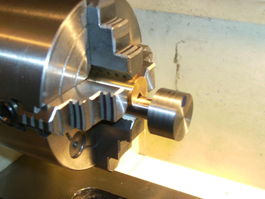
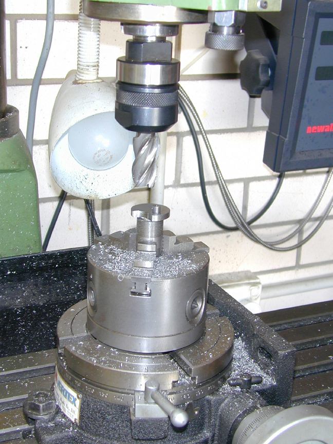
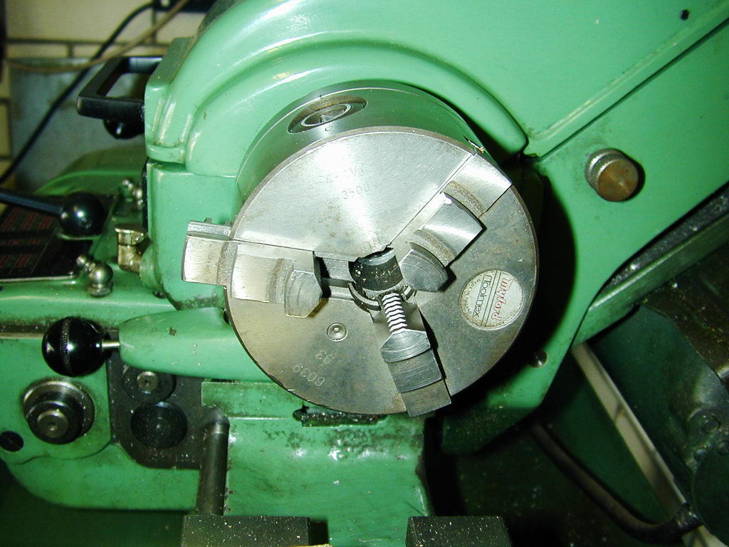 This technique appears in Dave Sugden's 1955 Aeromodeller series on building a high performance 2.5cc diesel engine. So I'm going to call it the Sugden Method even though it turns out to be not an uncommon "dodge" for model engineers for as long as they've had three jaw self-centering chucks. Dave's revelation is that it's possible to assemble the jaws of the chuck so that they don't self-center the work!
Place a finger on each jaw of the chuck, pressing them inwards as you open the chuck with the key. The first jaw to pop out of the scroll will be the #3 jaw. As soon as you feel it ride over the edge of the scroll start, stop and remove the jaw. The trick is to now close the chuck by a number of turns before replacing the #3 jaw. The chuck will now "center" bar stock offset towards the #3 jaw. How much will depend on the pitch of your scroll and where the jaw went back in in relation to the other two.
The Sugden Special itself has a stroke of 0.600". On my chuck, I found that two turns of offset produced a throw of 0.593". Not bad, but a little math shows this would reduce the engine displacement from 2.49cc to 2.46cc. So a piece of 0.004" thick aluminium drink can stock was placed under the #1 and 2 jaws. With everything tightened up, the DTI now showed that the bar was spinning off-center by 0.601". Close enough for jazz, I'd say.
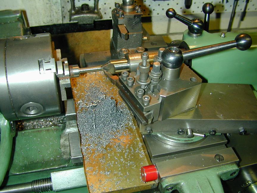
As noted by Dave Sugden, and as can be seen by the photos, the chuck on my Myford can't, as Dave put it, "swallow" the bar, so tailstock support is required while forming the pin. This can be a small center, and if you want, the pin can be made overlength and some or all of the center gently turned away when the pin is complete. If you are working on a small shaft in a large enough chuck, the support will not be necessary.
What we are really seeing here is a variation on using a 4-jaw independent chuck to grip the stock. The down-side is that the pin must be formed before the journal, and workholding for that is going to be just a bit harder, so we end up having to make a little jig after all.
Having turned the pin, but before returning the chuck to normal duty, chuck a stub of the same diameter (or larger) stock using the same shims. Now drill a hole through the stub about 0.010" larger than the crankpin. The hole will be offset from the center by the same throw as we have on the embryonic shaft. The extra diameter is for protective shim, so adjust the size as required by your shim stock.
After making the 3-jaw chuck truly self-centering again, center drill both ends of the crankshaft blank. Then chuck the offset-drilled stub and face it down so that the stub has a 60 degree "center" in its middle. Do not disturb this piece in the chuck until the shaft journal is complete. If you do have to disturb it, skim the 60 degree center again after re-chucking it to ensure the center is perfectly on the lathe axis.
Wrap a piece of the 0.004" drink can shim around the pin to protect it, then mount the shaft blank between centers. It will be driven by the actual crankpin which is adequately protected as long as you don't make any severe roughing cuts. As with any work done between centers, this approach has the advantage that the shaft can be removed from the lathe for testing at any time, and replaced with 100% accuracy.
This method, as some of you will have already observed, is similar to using a 4-jaw independent chuck for offset turning. It has the benefit of easy repeatability (when making the stub), plus not everybody these days has a 4-jaw chuck. Finally, while it feels a bit odd, it works, so add it to your bag of tricks.
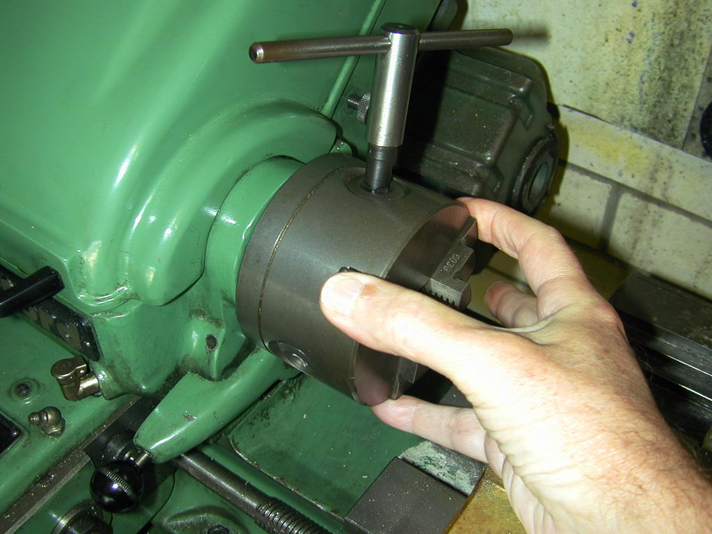
Bert's Variation
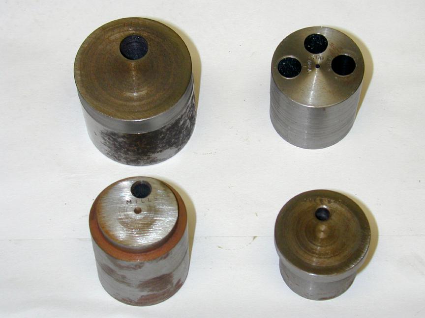
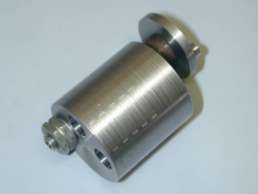
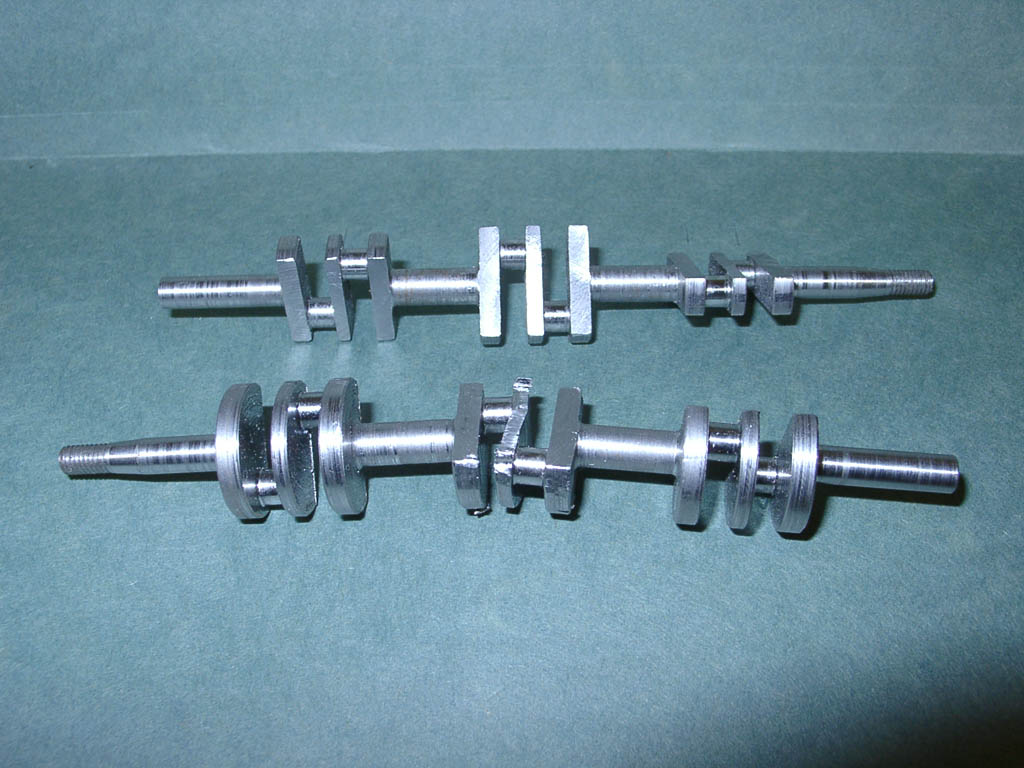
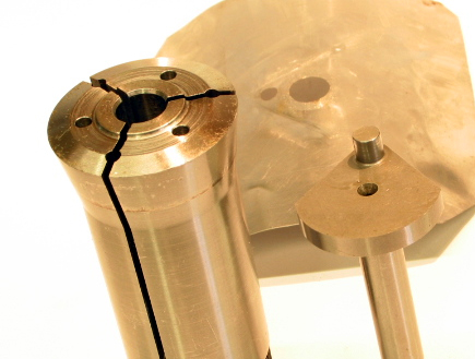
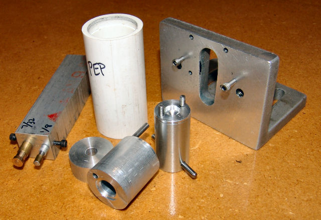 Bert Striegler has added an innovation to the method I've been using that makes a lot of sense and may induce me to change. The photo here shows the jigs and fixtures Bert made while building his Pepperell. The Crankpin turning fixtures are the cylinder with the pin and the thick "washer" seen in the lower left of the shot. First, here's Bert on how it works:
[The crankpin fixtures are] typical of the ones I make from scrap cut-offs. The main body of the crank tool is relieved in the front to accept the shaft thrust area while letting the main web sit flush on the tool. This piece is slightly longer than the bearing area of the shaft and is reamed to the shaft size. There is a 1/8" hole for the length of the fixture and a piece of 1/8" music wire that is the length of the main fixture body plus about another 1/16". It works like this: the music wire is sharpened on one end and the shaft is inserted into the reamed hole and set on a flat surface, then the wire pin is given a good whack with a hammer to put a pop on the inside face of what will become the crank web. The shaft is removed and a 1/8" hole is drilled in the front face of the web at the pop , about 1/16" deep. Now the shaft is reinserted into the fixture and the pin is pushed into the shallow hole, the rear piece that looks like a thick prop washer is slid over the threaded portion of the shaft and the prop nut is tightened firmly on the whole mess, trapping the pin in place. The shaft simply cannot rotate now. The shole fixture is put in the 4-jaw with a proper offset for the stroke and the pin can then be turned. Then the fixture can be put in a collet and collet holder for milling out the counterweight and side reliefs.
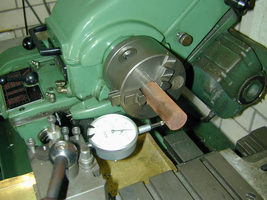
Notice that Bert drills his fixture axially for the shaft as opposed to the ones I've shown above which are drilled offset for the required throw. Bert's method, as he says, means he has a jig that will work for any shaft of the reamed size, and any throw—provided he can drill another 1/8" hole at the crank throw offset, accurate relative to the hole in the middle (not impossible, or all that difficult). The fixture then needs to be setup in the 4 jaw independent chuck so that the axis of the crankpin runs true. This can be achieved by clocking on the outside of the crankweb and un-formed pin blank—provided they have been trued up at the same setup used to turn and finish the main journal. A variation suggested by David Owen is to hold the shaft with set screws (pressing on copper pads to protect the shaft). This allows the 1/8" pin hole to be set to run true in the 4JIC before the shaft is inserted—an impossible task is the shaft is retained in the fixture by its prop nut.
My approach of drilling the hole offset simplifies setup as it merely has to be popped into the 3 jaw self-centering chuck. This greatly simplifies repetition work; an advantage to me as I frequently make more than one of a particular engine. The anti-disaster pin is a good idea too, although I've found that the propnut/screw holds the shaft in the fixture very firmly. And if it does shift, it's generally while you are taking big hogging cuts prior to the final light passes, so the shaft can be repositioned close enough that all will become well again in the final finishing cuts. The down side to my jigs is that they are dedicated to a particular journal size and crank throw, though I have managed to squeak more than one offset hole into the same fixture—suitably stamping each with the engine identifier for later reference. If I forget (and I have!) I end up with an offset drilled jig in the jig box and no idea what it was for.
Balancing
Yet another little task not often looked forward to with any relish is that of cutting the counterbalances into the crankshaft web (con-rod end profiling, 'shaft web cut-outs... is there any task we do look forward to?) I'll offer up my reason for this reluctance. Some parts take a lot of effort to produce, and effort equals time. As the process nears completion, the time investment is large and the opportunity to double the time taken by stuffing up the one in hand reaches a maximum—especially if some final operation requires a less than ideal set-up. Cutting the crank web cut-outs is one of those as it involves an interrupted cut coupled to a problem in workholding.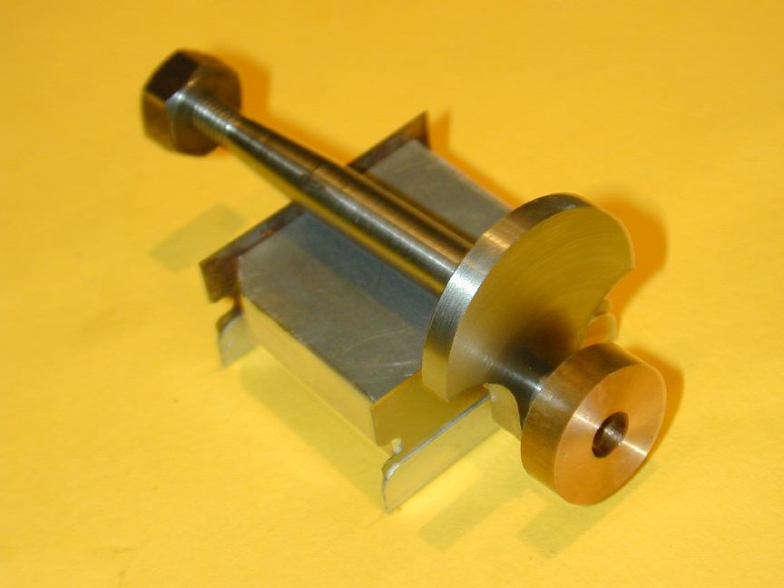 The purpose of cutting a relief in the crankshaft web is to achieve static balance. It is impossible to achieve perfect dynamic balance on single cylinder engines like ours. The best we can expect is a reasonable compromise by attempting to counter-balance one-half of the reciprocating mass of the engine, namely the piston, wrist-pin, and conrod little-end [LCM]. This is generally achieved by removing metal from the web so that the crankpin will sit horizontal when a weight equal to one-half of the reciprocating mass is acting through the axis of the crankpin. The photo here (from the 5cc Sparey Project shows a shaft set on knife-edges with a donut of the correct weight slipped over the crank-pin. Sadly, even with massive cut-outs, the shaft is not within coo-ee of being balanced. At this point, one can try adding lightness to the piston, but then you run the danger of having an easily distortable piston and subsequent loss of compression. I've had compression punch the crown out of one such light weight piston—a most unnerving occurrence!
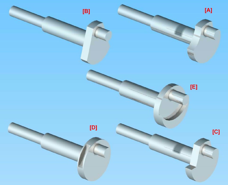
Obviously, the metal must be removed from the half of the crank web that carries the crank-pin. There are a number of ways of doing this; the picture here shows five of the most common approaches. I'll describe these before looking at workholding. The names used are in no way "official". I've made them up to be descriptive (I hope). Note there are other ways. These are merely the most common.
[A] Crescent Cut-outs
A large diameter cutter is used to take a bight out of the web on either side of the crank-pin. The center of the arc is arranged to minimise the amount of metal near the pin, consistent with retaining some strength in the web. The lower extent will be on, or slightly below the diameter of the web. A variant on this scheme is to drill holes in the web either side of the pin. I've even seen old designs that advocate filling these holes with aluminium. The idea being to achieve mass reduction without volume reduction. Another variant is to drill the holes on the opposite side and plug them with lead, tungsten, depleted uranium, or some other easily obtainable heavy metal.[B] Flat Segment Cut-offs
This is similar to [A], but does not require a large diameter cutter and offers some other options for work holding. The key point on this approach, and that of [A], is that the cut-out can extend beyond the diameter line (shown just a trifle exaggerated in the 3D rendering) to improve balance. The reason is that up to a point, the amount of metal being removed by the cut on the "heavy" side is less than the amount being removed on the "light" side, so the ratio heavy to light continues to increase until that critical point.[C] Obtuse Angle Cut-outs
This is a variation on [B], that retains all of the mass on the "heavy" side of the web, so instead of an arc, we have an obtuse angle. The downside is machining is more complex and you need to be careful that the intersection is not so sharp that it induces cracking. The style was used on a lot of old sparkers, and some more recent designs as well. One extreme I saw on an old design reduced the obtuse angle to a right angle![D] Peripheral Crescent Cut-outs
Yet another variation on [A], except the cut-out crescents are made in the edges of the web only. A thin ring is then generally shrunk over the web diameter to seal the edge. The objective is the have the effect of a full web on crankcase volume, while achieving some degree of balance. This approach has been used on commercial engines and high performance engines. It does require a thicker web than usual.[E] Web Thinning
A common "full-size" practice is to bolt (or otherwise secure) a weight onto the web opposite the crank-pin. Model designers frequently achieve the same effect by machining away the web concentric with the crank-pin. The result is more mass where we need it. Some designs supplement this with [A] or [B] type cut-outs. The down side is complication of the conrod profile to avoid having it clobbered by the counter-weight.Now onto workholding for making those cut-outs. This is usually the last operation to be performed on the shaft, so the opportunity for an accident to ruin hours of work is at a maximum. Here's how Bert Streigler setup to make type [B] cut-outs. The shaft in question is a Brown shaft and the cut-out is per this pioneer engine design. Bert says:
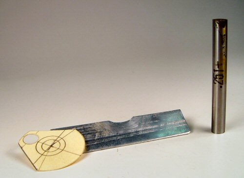
Here is a way I came up with. I don't have much in the way of measuring equipment, so I often resort to graphic set-up methods. One pic shows the little drawing, but I have since reverted to not even using that and simply do a drawing, then measure what pin is needed to get what I want. The three parts used in the set up are shown, and consist of a drawing to determine the pin size, a soft aluminium shield with a rather large cut out to allow the clamping of the crankweb without denting the inevitable radius where the web joins the shaft, and the required spacer pin.
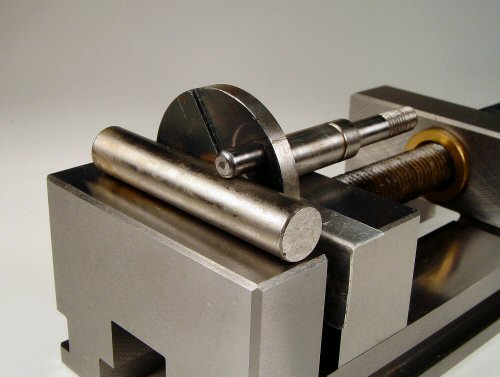
The second pic shows the set up. All I do is press down on the shaft to be sure it is in good contact with the top of the vice jaw, then roll it slightly until it is in good contact with the crankpin and then simply clamp down on it with the vice and machine. For the other side, just loosen the vise jaw slightly, roll the shaft the other way and clamp down again. This gives a perfectly symmetrical cut on both sides. All clamping is done on the web.
Ken Croft used a similar method for the crankshaft of the MS 1.24 (we don't always use the same method):
I don't know how you chaps do it, but when I have to cut slices off a crank disc for balancing, I so far have only a botched method for setting up. This has involved drawing the crank disc in TurboCAD and printing it out. I then cut out the drawing, glue it to the disc and then set it up by eye under the mill. The results is a long way from perfect and I am never satisfied.
So as it is a job I now have to do on the MS 1.2 copy that I am making, I thought about it and realised just how simple the job really is to do perfectly.
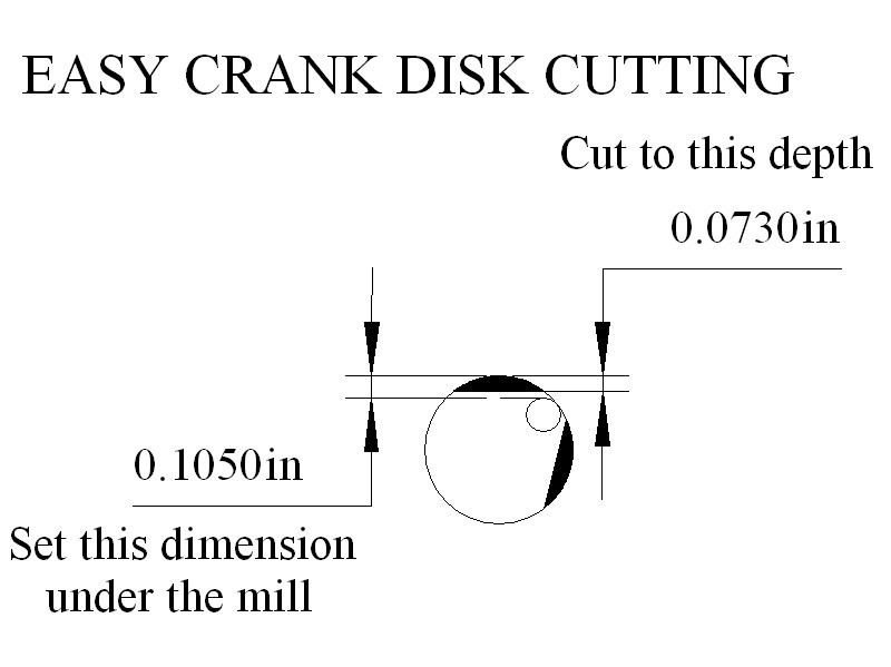
I drew the crank disc in TurboCAD, then used the model to take some measurements. I simply set the vertical pin to disc distance under the mill, using a flat ended probe and the downfeed register [I have a cheapo DRO on the mill].
I then end milled the required amount from the disc. I then rotated the disc and again set the pin to disc dimension the same as before, and removed an identical amount from the disc. The result is a perfectly symmetrical disc to exactly the required dimensions. Why did I not do it this way already?
Now I need to work out a simple method for scalloped cut-outs. That will not be so easy.
Bert and Ken have used two different measurement techniques to assure symmetry, but their basic approach is the same. We all agree that gripping the web in a mill vice is not without risk, especially if the crank is small. What goes unsaid between experienced model engineers is that the cutter should be sharp, the speed high, and the cut made so the teeth are meeting the work offset to one side to produce "conventional" milling (not "climb" milling). Even so accidents can happen to the best of us.
Clamping on the shaft affords the opportunity for a more secure set-up, but requires care not to injure what is probably a finely finished surface. Since cutter and shaft axes will be in-line using this setup, the cutter will be attempting to turn the shaft, opening us to just as much risk as before, unless a positive anti-rotation aide can be employed. Here's how David Owen made the segment cut-offs for the run of GB5's he and Gordon Burford produced.
I generally draw one-offs up on the crankdisc itself as you have done. Then I hold them in a 5c collet in the machine vice. Level them up against the line and register the pin height above the table with my vernier callipers. The actual dimension is meaningless. I trim down to the line as required and set the vertical stop. Then I turn the crank around until the pin is at the same setting on the other side, and cut down to the stop. I have used Bert's holding method but dislike it for the same reasons as your self.
On most cranks where the cut is a straight line diverging from the centre, removing metal below the centreline will result in greater loss above the centre, which is what we want. I've got the maths somewhere for this, showing the limits.
On cranks which have a scallop, or parallel cuts off the flank, the diameter is the limit. On this sort of crank, I mount in the 5c collet again, but with the shaft vertical.

On production shafts I have always drilled an 1/8" hole behind the crankpin as a register. You will see the three 1/8" dowel holes in the attached 5c image, which shows the GB 5cc shaft. The centre hole locates the shaft for roughing out the crankpin from the original full depth disc.
So I end up with a square crankpin about 1mm larger than the finished diameter and with about .25mm to come off the crankdisc face. All shafts are completed to this stage. Then the dowel is moved to a side hole and one flank machined away from each shaft.
The dowel is shifted to the other pin and the second flank is cut. The scruffy looking piece of shim keeps most of the swarf out of the vertical collet. The shafts are then chucked in the large 5c offset fixture in the Hardinge and the crankpin is turned to plus 0.2mm and the face cleaned up at zero. Then the shafts are hardened and finally ground.
The 3C collets used the way David has, are the bees knees for this job. The collet is keyed into the closer, so it can't rotate. Then the shaft is keyed to the collet with a 1/8" pin in shear (maybe hardened), so the shaft is not going to rotate, hence no teeth-clenching required. For one-off shafts, drilling a collet for the pin is probably out, but a correct sized collet exerts tremendous clamping force on the work, so this is still the best approach. By the way, look at the pin in the center of the offset crank turning fixture shown in the second photo. This will also prevent unwanted rotation of the shaft during crank-pin turning. Well worthwhile, especially if you're making 150 of them by hand!

I generally make an offset fixture to hold the shaft for crank-pin turning. This fixture can double-up to hold the shaft while machining away the web (although 3C collets in a substantial holder would be far nicer, if I had any). The photo here shows the fixture made for the AHC Diesel that was re-used for the Sparey 5cc diesel. In this case, the shaft is secured by tightening up the prop nut, but a pin like David used with this 3C fixture would be good insurance. The holding fixture is gripped in the 3 jaw chuck, screwed to the rotary table mounted horizontally under the mill. It could also be held in the mill vice using a V-block.
 The crankdisk is marked for the cut-out using a template like Bert's. In the case of the AHC and Sparey, a 3/4" end-mill was the largest available, so that sets the crescent radius. The cutter is positioned to touch as much of the marked line as possible while stationary and the mill axes zeroed. I then "nibble" away the web from the outside in using the down-feed, moving one mill axis between cuts, and advancing no more than 0.030" at at time, with tightly clenched teeth. When the "zero" point is reached, the quill is locked down, then the sides of the cut are cleaned up by winding along one axis from zero, then back to zero and winding the other handle. A sharp cutter will do this smoothly. A dull one will shudder and bump, and try to snatch the work. Even a sharp cutter will raise a light burr at the edge of the cut. This is dressed off with a small grinding stone in the Dremel hand-tool—taking great case not to cause a run-away that hits the crank-pin (more teeth clenching required).
Examination of a *lot* of engines and drawings in the "sport" class shows that below 2cc (0.15 cuin), most experienced designers do not bother to cut away the web. My own experience supports this. The amount of vibration experienced by small engines is not great, and theory suggests that the lower crankcase volume resulting from a full web will make the engine a better fuel pump—though given the ability of small engines to flood up, this is not often a major concern.
References:
| [LCM] | Mason, LC: Experiments with Small I.C. Engines, Model Engineer Vol 137 No 3430, June 7, 1971, Model and Allied Press, England, p 1152. |
![]()

This page designed to look best when using anything but IE!
Please submit all questions and comments to
[email protected]
Copyright (c) Ronald A Chernich, 2005. All rights reserved worldwide.