Model Internal Combustion Engines
Frequently Asked Questions
From time to time, I get emails from people seeking simple answers to questions that are easy to answer, if you know where to look. While responding to one, I suddenly thought, "why not compile a genuine web-style FAQ (Frequently Asked Questions) page?" Obvious. Should have thought of it years ago...
Now, the disclaimer: the answers provided below come from my personal lack of knowledge and wisdom (unless otherwise stated), and since I'm a professional software engineer, not any kind of trained machinist, nor motive engineer, all are likely to be inaccurate, incomplete, misguided, or even just plain wrong. Believe them at your own peril!
- How do I become a Member of Model Engine News and what does this get me?
- There are a few basic questions I want to ask about the diesel engines, here goes: Do they run on automotive diesel?
- How does the intake on the Weaver work?
- How does the fuel stay in the cylinder [of a two-stroke] while the exhaust is escaping?
- Can I run these [diesel] engines on R/C buggy fuel, Nitro methane / oil mixture?
- Should I replace castor oil with modern synthetic oil?
- I'd like to get started in model engine building. What do I need?
- How do you make press-fit contra-pistons for your diesel engines?
- I read about a lapping tool for finishing pistons. Is this tool one of your designs?
- I've never run a "diesel" engine before. How do you start them?
- I'm new to this—what's the difference between an "End Mill" and a "Slot Drill"?
- Where do I get diesel fuel from in the USA?
- How do I make my new, bright, and shiny brass bits look less new, bright, and shiny?
- What are typical compression ratios for small IC engines? Does it vary between two-stroke and four-stroke engines?
- Where can I buy ether for diesel fuel in the USA?
- Why doesn't the contra piston go up and down with the piston when the engine is not firing? Or does it?
- What is the minimum machinery and tools I need to start making my own model engines?
- How much nitromethane should I use with my engine?
- How does a glow plug work?
- What is a "De Sax engine"?
- What are the main types of metal casting procedures? How does the metal get into the mold or die, and how can I tell one type of casting from another?
- How do I wire up a "Sparkie"?
- I have seen on your site and other sites references to 2 cycle engines running a 4-2-4 pattern. A four cycle, two cycle, four cycle. How does that work? Don't you need a geared camshaft to be able to run 4 cycle? I am obviously missing something here. Any help clearing the fog would be appreciated.
Question:
How do I become a Member of Model Engine News and what does this get me?
Answer:
Dear Dorothy, "Life Membership" is included with purchase of the MEN Only DVD (that's my life we are talking here  ). I want to keep this web site as an Advertising Free Zone. That means that I have to pay for the storage and bandwidth, so it's the sale of the disks that offsets this cost. As a way of saying thanks to the contributors, "Members" get access to restricted pages and twice a year, they get complete, fully detailed, model engine construction plans, absolutely free, for their personal use and/or enjoyment. These plans are also included with the DVD, plus a copy of the Motor Boys Plan Book, another thirteen fully detailed CAD plan sets. The disc will be fully up to date at the month of your order and updates to keep it current are downloadable from the Members' page each month. Registered owners can get an upgrade disk mailed to them anytime for a nominal fee. What's "nominal" you ask? Follow this link to the current prices and easy to use PayPal links.
Question:
There are a few basic questions I want to ask about the diesel engines, here goes: Do they run on automotive diesel?
Answer:
No, not exactly. Model diesels are not real "diesels" in the strict sense of the term. Full size diesels compress air, raising its temperature, then inject a mist of fuel which ignites in the hot air. Model "diesels" are actually "compression ignition" engines. They compress a fuel/air mix with a very low flash point that self ignites. The standard fuel is an equal parts mix of kerosene, castor oil and ethyl ether. It is the latter that provides the low flash point. Ether used to be available over the counter in chemist stores, but as it is now used by back-yard labs to make amphetamines and other "party drugs", obtaining it is becoming very difficult. In days of yore, amyl nitrate was added (with an eye-dropper) as an ignition improver. We used to buy little bottles of that at the local drug store too, but this stuff speeds up the heart like crazy (instant high) so no chance of buying any today! A modern substitute is DII (Diesel Ignition Improver), but it can be hard to find as well. If you can get it, 2% by volume is about optimum to add.
But back to the original question... while kero, castor and ether are the standard mix, I've seen model "diesels" run on the most amazing assortment of brews and I've heard that automotive diesel can be substituted for the kerosene in the standard brew. This may even be better as it is cleaner than home kero used for heating. When I was a kid at primary school, maybe 9, or 10, we all mixed our own fuel. One of our merry band, needing fuel for the next day and having run out of the medicinal castor we used to buy, substituted peanut oil. His engine ran fine, even if it did blow more smoke than normal and smell like a fish 'n chip shop!
While I don't know from squat about fuels, I have a friend who is a certified expert in the subject: Bert Striegler. Here's a little of his wisdom:
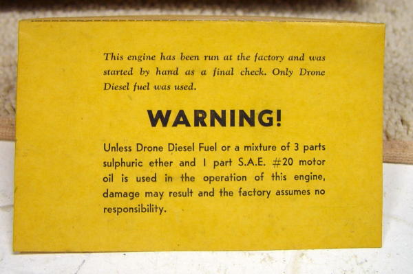
Bert's observations are reinforced by Adrian Duncan's treatise on Operating Fixed Compression Diesels which also explains the logic behind the apparently wild brew specified by the Drone warranty card. You should also read the Marshall page on Miniature Engine Fuels, and QA #9 on operating variable and fixed compression diesels.
Question:
How does the intake on the Weaver work?
Answer:
This question and the next are closely tied. The Weaver belongs to a family known as "side-port" induction engines (or less frequently "three-port" engines). Side-ports use the piston to control the time and duration of the three basic internal combustion gas moving operations: intake, exhaust and transfer. This is done by arranging three openings in the cylinder that are uncovered by the piston top as it moves downwards (exhaust and transfer), and piston bottom as it moves upwards (intake). Because intake and exhaust/transfer are controlled by the piston, their durations are symmetrical around TDC and BDC respectively, hence side-ports will run equally well in either direction (and start backwards when you don't want them to!)
Consider what's going on as this piston rises to Top Dead Center (TDC): since the crankcase is effectively closed, the increasing volume reduces the pressure inside, relative to atmospheric pressure. Just before TDC, the bottom of the piston skirt uncovers the inlet hole causing air to rush in, attempting to equalize that pressure imbalance. From the open end, the inlet pipe tapers to a lower diameter at the point where the spray-bar is positioned. It then increases again forming what is called a "venturi".
What takes place now is rather like how siphon-type spray guns work, or old fashioned, pump-handle fly-sprays, if you've ever heard of such things! Venturi effect reduces pressure at the point of maximum constriction. Since this is the point at which hole in the spray bar is positioned, fuel is drawn from the tank and atomized by the very fine hole to enter the crankcase as a fine mist along with the air. The needle valve provides a fine control over the amount of fuel drawn in during this operation and hence the fuel/air ratio. The descending piston closes off the inlet hole and then compresses the fuel/air mix in the crankcase. This is termed "primary compression".
Question:
How does the fuel stay in the cylinder [of a two-stroke] while the exhaust is escaping?
Answer:
Not all that well! Two stroke engines fire on every revolution, so exhaust and transfer must take place at the same time. Transfer is the process of moving the compressed fuel/air mix in the crankcase to the above the piston. Since this takes place during the period the exhaust is open, it is the design of transfer ports, exhaust and piston that determines the "scavenging efficiency"; ie, how much exhaust and new charge is expelled through the open exhaust port(s) verses how much of the new charge and burnt gas is retained in the cylinder for secondary compression and combustion. This is common to all 2-strokes and is one of the reasons some governments are considering banning the type all together because of their contribution to hydrocarbon pollution.
Typically, a 2-stroke exhaust opens a few degrees before transfer starts. This means that most of the pressure in the cylinder has been relieved by the time the transfer port(s) open. Because the fuel/air mix in the crankcase is compressed, it enters the cylinder at high velocity. Hopefully, most of the new charge is directed up into the top of the cylinder before pressure drops and you start loosing it out the still open exhaust. A desirable, but secondary effect of this to have the new charge assist is pushing burnt gasses remaining in the top of the cylinder down and out.
The Weaver design uses those 5 little channels connected to a "transfer band", the top of which is angled upwards. Hence, when the band is uncovered, a cone of new mix forms in the middle of the cylinder, blowing upwards, displacing any remaining burnt exhaust sideways and down, thus aiding the scavenging efficiency. A similar concept frequently used in British and Australian "diesels" is to form a shallow cone on the top of the piston, again trying to deflect the new charge up, away from the open exhaust ports.
There are many, many other schemes. The most efficient is "Schnurle porting". This comprises (generally) a single exhaust with two transfer ports at 90 degrees, or less, either side of the exhaust and cut so as to direct the new charge to the side opposite the exhaust. A third "boost" transfer port, opposite the exhaust, is timed to open after the primary transfer ports and blow upwards.
Some transfer systems also place a baffle on the piston crown to deflect transfer upwards. This is called "loop scavenging".
Question:
Can I run these [diesel] engines on R/C buggy fuel, Nitro methane / oil mixture?
Answer:
Sorry, no. R/C buggies today use glow plug engines. These run on a mix of methanol and oil, frequently with some percentage of nitro methane added as a go-fast ingredient. The ignition temperature for this fuel is much, much higher than that obtainable in compression ignition engines. You can comfortably place your fingers on the cooling fins of most diesel engines, like the "Deezil" for example, while they are running; you can't do that with any glow motor I know of, not even the teeny-weenie ones. This shows just how much of a lower temperature the "diesel" mix burns at. That said, there have been rare, reported instances of glow engines starting through self-ignition. I was holding a U/C stunter with a Fox .35 in it that started like that accidentally—the battery was not even attached! But this is such a rare event, you could go through several lifetimes and never experience it.
Question:
Should I replace castor oil with modern synthetic oil?
Answer:
Tricky question, and not one I'm in any way qualified to answer. There's a lot of folk-lore and ju-ju thrown about on this topic. Instead of poking my vulnerable neck out, here's some words of real wisdom on castor from the master: Bert Striegler. Read it and decide for yourself!
Back in 1983 there was quite a controversy in Radio Control Modeller magazine about the tests that were necessary to measure the "lubricity" of various oils that might be useful in model engines. Castor oil was used as the benchmark, but it was obvious no one knew why this was so. They apparently got a lot of info on various industry tests of lubricants, but these were really designed for other purposes. This was my answer. I will remind you that I was a lubrication engineer and not a chemist, but I drew my chemical info from Bob Durr, the most experienced lubricant scientist in the labs at Conoco. Bob worked with my group on many product development projects and I can tell you that he is one smart hombre! Small changes were made in the text, but surprisingly very little has really changed since this was originally written. Here goes with the answer:
"I thought I would answer your plea for more information on castor oil and its "film strength", which can be a very misleading term. I have never really seen a satisfactory way to measure the film strength of an oil like castor oil. We routinely use tests like the Falex test, the Timken test or the Shell 4-ball test, but these are primarily designed to measure the effect of chemical extreme pressure agents such as are used in gear oils. These "EP" agents have no function in an IC engine, particularly the two-stroke model engine types.
You really have to go back to the basics of lubrication to get a better handle on what happens in a model engine. For any fluid to act as a lubricant, it must first be "polar" enough to wet the moving surfaces. Next, it must have a high resistance to surface boiling and vaporization at the temperatures encountered. Ideally the fluid should have "oiliness", which is difficult to measure but generally requires a rather large molecular structure. Even water can be a good lubricant under the right conditions.
Castor oil meets these rather simple requirements in an engine, with only one really severe drawback in that it is thermally unstable. This unusual instability is the thing that lets castor oil lubricate at temperatures well beyond those at which most synthetics will work. Castor oil is roughly 87% triglyceride ricinoleic acid, which is unique because there is a double bond in the 9th position and a hydroxyl in the 11th position. As the temperature goes up, it loses one molecule of water and becomes a "drying" oil. Castor oil has excellent storage stability at room temperatures, but it polymerizes rapidly as the temperature goes up. As it polymerizes, it forms ever-heavier "oils" that are rich in esters. These esters do not even begin to decompose until the temperature hits about 650 degrees F. Castor oil forms huge molecular structures at these elevated temperatures - in other words, as the temperature goes up, the castor oil exposed to these temperatures responds by becoming an even better lubricant!
Unfortunately, the end by-product of this process is what we refer to as "varnish." So, you can't have everything, but you can come close by running a mixture of castor oil with polyalkylene glycol like Union Carbide's UCON, or their MA 731. This mixture has some synergistic properties, or better properties than either product had alone. As an interesting sidelight, castor oil can be stabilized to a degree by the addition of Vitamin E (Tocopherol) in small quantities, but if you make it too stable it would no longer offer the unusual high temperature protection that it did before.
Castor oil is not normally soluble in ordinary petroleum oils, but if you polymerize it for several hours at 300 degrees F, the polymerized oil becomes soluble. Hydrogenation achieves somewhat the same effect.
Castor oil has other unique properties. It is highly polar and has a great affinity for metal surfaces. It has a flash point of only 445 degrees F, but its fire point is about 840 degrees F! This is very unusual behavior if you consider that polyalkylene glycols flash at about 350-400 degrees F and have a fire point of only about 550 degrees F, or slightly higher. Nearly all of the common synthetics that we use burn in the combustion chamber if you get off too lean. Castor oil does not, because it is busily forming more and more complex polymers as the temperature goes up. Most synthetics boil on the cylinder walls at temperatures slightly above their flash point. The same activity can take place in the wrist pin area, depending on engine design.
Synthetics also have another interesting feature - they would like to return to the materials from which they were made, usually things like ethylene oxide, complex alcohols, or other less suitable lubricants. This happens very rapidly when a critical temperature is reached. We call this phenomena "unzippering" for obvious reasons. So, you have a choice. Run the engine too lean and it gets too hot. The synthetic burns or simply vaporizes, but castor oil decomposes into a soft varnish and a series of ester groups that still have powerful lubricity. Good reason for a mix of the two lubricants!
In spite of all this, the synthetics are still excellent lubricants if you know their limitations and work within those limits. Used properly, engine life will be good with either product. Cooked on a lean run, castor oil will win every time. A mix of the two can give the best of both worlds. Most glow engines can get by with only a little castor oil in the oil mix, but diesels, with their higher cooling loads and heavier wrist pin pressures, thrive on more castor oil in the mix.
Like most things in this old life, lubricants are always a compromise of good and bad properties. We can and do get away with murder in our glow engines because they are "alcohol cooled" to a large degree. Diesels, though, can really stress the synthetics we use today and do better with a generous amount of castor oil in the lubricant mix. Synthetics yield a clean engine, while castor oil yields a dirty engine, but at least now you know why!"
But wait! There's more (Bert again):
I have been thinking for a while about how to answer your seemingly simple question, "What is the flash and fire points of SAE 70 motor oil?". I was always told that engineers are people who can make something complicated out of something simple, and that is what I am going to have to do!
First of all, there is not now and has never been such a product as an SAE 70 oil. The SAE grading system used to stop at 60, and for all practical purposes, is now limited to 50. It is an arbitrary system based on the viscosity of lighter oils at 0 Degrees F. and heavier oils at 210 degrees F. The reasoning was that 0 degrees was about as low as you could expect to be able to start an engine, and 210 degrees was about as hot as you expected the oil to get in a crankcase. This scale was produced years ago, and today we routinely start gasoline engines at temps of -40 degrees F, and some of our crankcase oil testing is done in engines at oil temps of 330 degrees F and higher.
We used to make Conoco 70 oil, and it was basically a blend of bright stock and a little bit of 800 pale oil. These are the two products I will use as an example of why I cannot answer your question straightforwardly. Oil base stocks are usually produced in a vacuum distillation tower after all the lighter ends of the crudes are driven off. This is a process carried out under a 2MM vacuum. Our 5295 bright stock first starts boiling off in this tower at about 500F. 5% is boiled off at 560, 20% at 600, and finally 50% at 650, at which point the oil begins to "crack" into lighter and heavier products. The point is that, unlike synthetics, we are dealing here with a product that boils off in varying degrees in a range of temperatures from roughly 500F to 650F and then cracks. 800 pale oil is a lighter product which starts boiling at about 375F and finally starts cracking at about 630F. From the distillation curve, I would estimate the flash of bright stock at about 560 and 800 pale at about 475F. A blend of the two would flash closer to the 800 pale number that to the bright stock number. Different folks made 70 oils in different blending fashion, so no two brands would yield the same flash or fire points. We never used "dumbbell" blends at Conoco. By that I mean a blend of very heavy oil and very light oil to get a medium oil viscosity. We used to see a lot of this type blending and it is not good.
With petroleum oils, the fire point is usually 60 to 80 F above the flash point, very close to the cracking temperature. What does all this mean? Practically nothing, because in practice we don't usually reach these kind of temperatures EXCEPT where the oil is mixed into the fuels. Oil carried into the combustion chamber can be exposed to cracking temperatures. Have you ever had a really black exhaust with an ignition engine using petroleum oil lubes? I have, and it is even more common in diesels. What that tells you is that the oil is cracking, that burning of the oil is incomplete and the black is plain ole carbon. So, petroleum oil is a little bit like castor in that it comes apart over a wide range of temperature. Synthetics, on the other hand, boil, flash and then burn in a very narrow range but when they do burn, they normally burn completely with a clear and clean exhaust. That's why they leave less oil on the airplane.
Everything I just told you is in regards to paraffinic base oils, but there are also naphthenic base oils around. They produce less carbon, have a lower wax content and thin out more quickly with a rise in temperature than the paraffinic stocks. Naphthenic stocks are preferred in large gas engines and other operations that are sensitive to carbon buildup over a long period of time, but these stocks are more sensitive to oxidation and have a lower flash and fire point. Paraffinic oils are better lubricants in most operations. Paraffinic oils used to be called "bright" oils or "green" oils because in sunlight, a clear bottle filled with paraffinic oil had a bright green "bloom" when looked at with the light coming through it. Naphthenic stocks have a pale blue "bloom" and used to be sold as cheap engine oils in years past. I don't think a naphthenic based motor oil would be able to pass our modern engine tests and they are rarely seen anymore.
In a nutshell, you are not really going to burn a 70 oil in the combustion chamber and flash and fire points are a non-issue. I quit using 70 oils a long time ago because of the carbon problem. Modern outboard motor oils are SAE 40 oils with ashless additives and are diluted 20% with a high grade kerosene to assure easy mixing. One of the tests that they have to pass is a wide-open throttle test in a 100 HP outboard pulling about 60HP on the dyno using a 300 to 1 mix of the diluted oil in gasoline! This is a 100 hour test, or was when I was involved. The engines looked really good and all parts were measured before and after the testing was done. That is not a mistake, 300/1! Some of these oils are synthetic, blends with synthetic and petroleum oils, and straight petroleum oils. All have an elaborate, ashless additive system.
For our purposes, castor is still the best. The heavier petroleum oils share a wide distillation range so they offer some lean run protection like castor. The synthetics perform well in our engines unless you reach their boiling point, at which point you are dead meat. A good rule of thumb is "The messier the airplane, the better the lube is working." There is really nothing wrong with burning the synthetics in the combustion chamber. The only caution is that if the engine gets off too hot and the cylinder walls reach the boiling point of the lube, then all is lost. That is not likely to ever happen with petroleum or castor oils in the SAE 40 range of viscosity.
Question:
I'd like to get started in model engine building. What do I need?
Answer:
Deep pockets!  Well, maybe not; depending on what sort of equipment you already have, or can get access to. Roger Schroeder wrote extensively on this topic some time ago and you can read his recommendations here. Some builders are immensely talented and tenacious. They are the sort who decide to build 9 cylinder, sleeve-valve radials as their first project, and succeed! The rest of us should pick something simple, not too small and not too large. A 2cc diesel is a good choice for your first project.
Question:
How do you make press-fit contra-pistons for your diesel engines?
Answer:
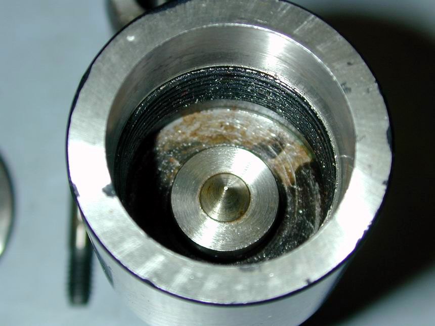
Getting the correct fit for the contra-piston in a conventional diesel, or more correctly, compression ignition engine, is critical. It needs to be tight enough to maintain a gas-tight fit over its operating travel, yet loose enough to move easily with the small amount of mechanical advantage available from your typical compression screw "tommy-bar". US manufacturers like OK and McCoy solved this problem by using a high temperature "O" ring seal. Purists cry that this destroys the "feel" of the engine, and the "O" ring will deteriorate, over time. I tend to agree, preferring the British and Australian diesels with their carefully fitted, cast iron contra-pistons (CP's).
The problem is compounded by the fact that the bore on "diesel" engines should have a light taper, narrower at the top opening. To a degree this is counteracted by the tendency for the opening to bell-mouth when lapped using our common home-made finishing techniques, as opposed to the ground bores on commercial engines. What to do?
Initially, I was making CP's by tapping an over-size blank, fitting this to a threaded mandrel, then turning it a few thou oversize and lapping (or honing) to a trial fit. Using a mandrel allows the CP to be offered up to the bore in the correct orientation while still in the lathe. If the fit was too tight, the CP could be knocked out, re-fitted to the mandrel and another half a milli-qoumpth removed. Too much and the CP went into a little bag of CPs that reminds me not to be so impatient. Then David Owen told me how to make perfect CPs, every time, with little effort and no lapping/honing. Basically, the CP is made with a slight taper (set you top-slide over by about 0.5°, or less) and very thin walls about 0.5mm thick (say 20 to 25 thou). The taper allows you to gauge when the piston is almost turned to the right size for final lapping. The thin walls will compress to give a perfect seal and feel over the operating length. How this is achieved is explained, with pictures, in Part 6 of the Weaver story.
One last word on making CPs. A steel CP in a steel liner will work well enough, but will "freeze" up soon after the engine starts, so you need to make any adjustments quickly. Best results are obtained using cast iron CPs in a steel liner. I'm guessing that the different thermal expansion coefficients have something to do with this, but the lubricating properties of the graphite in cast iron could have an impact too. In one instance, I've used an aluminium CP that worked extremely well. You can read about that in the Vivell 09 article.
Question:
I've ordered the casting kit for the ED Baby from Roger. In getting the material and tooling together to make this engine, I read about a lapping tool for the piston. Is this tool one of your designs? If it is, would you consider parting with some information and sketches, so I could make one? Making one tool to lap many sizes of pistons make much more sense than making a dedicated lap for each and every size piston.
Answer:
The little tool I use appeared in the English magazine Model Engineers Workshop of Jun/Jul, 1997. It was made from a kit available from Bruce Engineering in the UK, but you don't need this article to make the kit. Bruce have now been absorbed in to Polly Engineering who can supply the kits and hone stones.
Design wise, their tool is a close copy of the small Delipina External Hone. I've used it to hone pistons for engines in the range 0.5cc up to 6cc, though it could go smaller and larger. The tool can be seen in use in the pages that detail the piston and cylinder finishing of the Weaver construction. It's use is not limited to pistons either. Mine is also used to finish crankshafts to a highly polished running fit in their bearing.
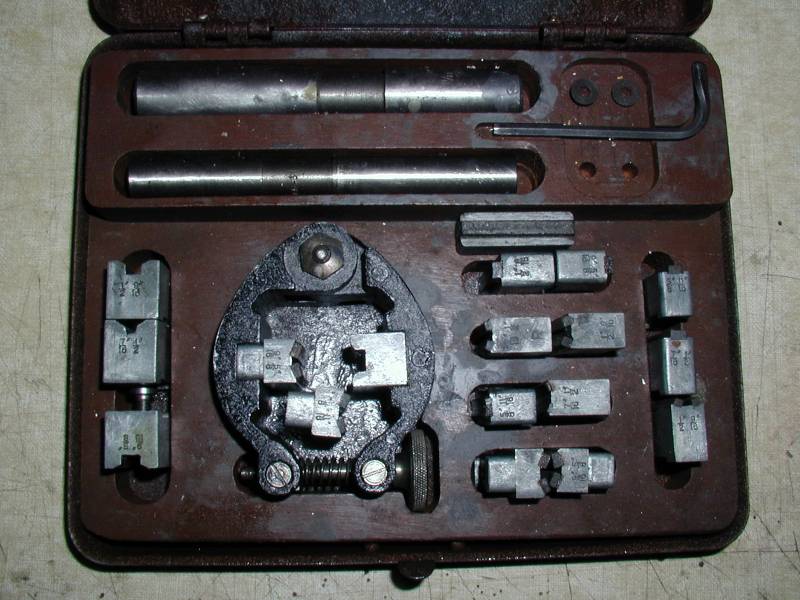
Dave Owen also swears by them (he has an original Delipina in wooden box, with a range stones and spacers as pictured earlier). Dave strongly recommends that you keep a couple of "truing bars" with your hone. This is just a longish bar of steel, or cast iron that you take a few passes over before starting in on the piston. I think the theory is that a piston will be shorter than the stone, so in time, the stone will wear more in the middle. A few passes over a long round bar before each job will keep you stones from making barrel shaped pistons.
The other way to go is to make an adjustable lap for every piston. Such purpose made external laps are easy to make, but a bit tiresome. There's a picture of one in the tooling photo on the Deezil page. This sort is made to the piston diameter, plus a thou or two from something soft like aluminium or brass. It is "charged" with diamond past by rubbing the paste into the inner surface using something very hard like a piece of round high speed steel (HSS). It is adjusted by placing it in the lath chuck and tightening it! You also have to make a carrier for the piston to stroke it in and out of the lap (with lots of oil).
Regardless of how you do it, after the honing (or lapping) operation is complete, be sure to remove the sharp edge at the top and bottom of the piston. If you don't, the piston is going to make a very good oil scraper and remove the oil from where it is needed most. I do this using a fine stone like an "Arkansas" honing stone, hand held at about 10 degrees from the horizontal. A few seconds of this top and bottom will produce a small bevel that will act to hold the oil film on place rather than scraping it away. After a few runs, tear down the engine and examine the piston. If the wear band goes right to the crown, or skirt, it is probably running close to un-lubricated. Finally, the piston and liner need to be cleaned very thoroughly to get all abrasive residue off them before assembly. A small ultrasonic bath is ideal if you can spare the expense. These are available from jewelers' supply stores.
Question:
I've never run a diesel engine before. How do you start them?
Answer:
Yes, this can be a bit of a mystery the first time, especially if it is an engine you've just built and don't know if it will run at all! The engines we call "diesels" are really compression ignition engines as the fuel arrives in the cylinder ready mixed with air where it is compressed until it reaches the Self-Ignition Temperature (SIT). Real diesels inject a mist of atomized fuel into an compressed—hence heated—volume of air where it commences to burn. But diesel is easier to say than compression ignition and modelers have been using that name for over 60 years, so let's adopt it here, knowing what we really mean.
Diesels come in two flavors: variable and fixed compression. Fixed compression diesels today are unheard of outside of vintage engine collections and never really were all that common. The operating technique and fuel for both is subtly different. The standard brew for a variable compression diesel is covered above (see QA #1), which also mentions the rather strangely different mix recommended for fixed compression diesels.
In general, diesels are relatively hi-torque compared to glow engines, especially long stroke side port types. So a 2cc like the Deezil, or the AHC will swing a 12" prop, a 1cc like the Weaver an 8". A 5cc like the Nova, Delong, or Sparey will happily swing a 16". For those accustomed to glow engines, go a bit over the size of prop you'd usually fit to get some extra flywheel effect. A side benefit to this is a reduction in the tendency to backfire, especially if not flicked over smartly, which will bite you on the fingers, every time.
And never, never, never, repeat three times and say after me, never use an electric starter on a diesel. High compression ratio plus flooded engine and electric starter equals bent rod, or broken crankshaft. You have been warned. As for the actual starting technique, have a look at these two pages:
Question:
I'm new to this—what's the difference between an "End Mill" and a "Slot Drill"?
Answer:
Ho ho, you asked for it! By strange coincidence, the Aug/Sep 2002 edition of Model Engineers Workshop magazine (British) starts a series on milling for beginners and addresses this exact question. I also have to reiterate that I am no kind of trained machinist, so the information below is my poor interpretation gleaned from several sources and should be taken with at least one grain of salt!
In the small sizes (3/32" to 3/4", and 2 to 20mm), we see 3 basic kinds of milling cutters with two kinds of shanks. These are available in metric and imperial sizes. The most common types are the 4 flute "end-mill" and the 2 flute "slot drill". The most obvious difference, apart from number of flutes, is evident looking end on: a slot-drill's flutes meet in the middle, so it can be used do form a flat bottomed hole, or slot. The end-mill will have relief ground into the area where it's teeth meet. Larger ones even have a center drilled in there, so it will (1) not drill a flat bottomed hole—there will be a cone formed in the center that will limit how deep it can go, and (2), if you try to mill a slot with it, it will leave a snail-trail in the middle.
However, with 4 teeth per rev, you'd think an end-mill would be able to remove metal faster. Strangely this turns out not to be the case. The Rule for maximum cut (for any cutter of diameter "D") is:
Slot-drill:
  max depth per pass = D/2
  (so volume of metal removed = D^2/2)
End-mill:
  max cut depth = D, with max width = D/4
  (so volume removed = D^2/4, half that of the slot drill)
End-mills should only be used for profiling—it is impossible to mill a straight slot with one due to the way the teeth will engage with the work and act to pull the tool towards one side (the descending cut side I think, but I'd have to check a reference — George Thomas' "Model Engineer's Manual" which I believe is a must-have work for amateurs, especially those with a certain well-known, funny English Lathe). A slot drill however, will cut a straight slot, but it will also be over-size. Only way to get around this (if it really matters), is use a slot drill 1/32" or 1/16" smaller, then take climbing mill cuts on each side to the desired width. Because they can be "plunged" in, slot-drills can also be used to machine blind slots.
- [Aside] a "climbing cut" is one where the tooth first contacts the job at a shallow depth (zero actually, after the cut is established), and is pushed deeper into the material by the traverse as it climbs up the slope and out of the surface. In effect, it is trying, but failing, to push the work away. The opposite, a descending cut, has the tooth first contact the work at the maximum depth on the surface and cut progressively shallower as it descends. But in so doing, it is trying to snatch the work into the descending tooth. This gives an uneven surface to the cut. Generally, all profile milling should be done using only climbing cuts. [End of Aside].
The 3 flute cutter is called a "mini-mill" and seems to be a bit rare. The teeth meet in the middle, but I've never used one, nor seen one for that matter. The MEW article does no more than mention them either. The shank size of both end-mills and slot-drills is standardized to 4 sizes in imperial and metric. There are 2 different shank styles called "plain" (which is actually threaded) and "throw-away", or "disposable" which is actually plain!
|
|
|
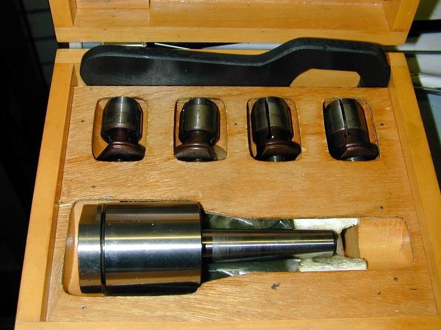
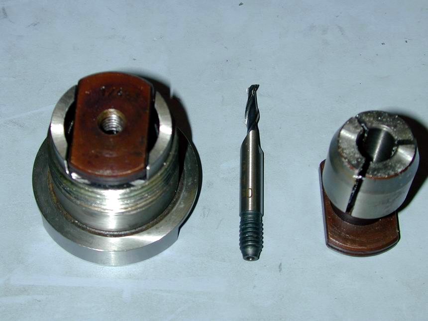
The Brits (and through Cultural Imperialism, Australians and New Zealanders) seem to favour the screwed shank type cutters. These must be used with a collet style holder known as an "Auto-Lock" holder. The one in the photo has a #2 Morse taper shank and 4 imperial collets that cover all the cutter sizes available. As we shall see, the giant spanner in the box is used to remove the cap, not to tighten it. Each collet is internally threaded below the slit portion for the corresponding cutter. Cutters have a female center in their base which mates with a male center in the holder body. The collet is closed by a mating taper in the screw-on holder cap. When load is first applied to the cutter, if it can rotate at all, its right hand thread will screw it into the holder until it is stopped by the center. If it can still rotate, it now acts like a jack screw and forces the collet up into the cap, firmly closing the collet—hence the term "auto-lock", and the need for the giant cap-removal spanner! The advantage of this style lies in the cutter being locked absolutely rigid in the holder, with any variation in cutter shank diameter, allowed by the manufacturer's tolerance, being taken up by the collet.
The disposable type (popular in the US) have straight shanks with a milled flat for a grub screw that will prevent rotation. It will also prevent the cutter being pulled out of the holder, but it does allow some initial longitudinal movement as load is first applied. You will also strike the odd cutter that is loose, or tight in the holder due to permissible tolerance of the shank. Cutters that won't go all the way into the holder are a pain—and I have several! Obviously these are cheaper to manufacture, hence the "throw-away" approbation, I guess. Personally, I prefer this type, and not because they are cheap (well, not only, anyway). The auto-lock holders by necessity, are large beasts, while the holders for disposable cutters are not that much larger in diameter than the cutters themselves and have tapered noses. Model engineers frequently have to machine into very confined areas and it seems that just as often as not, I can't get a "plain" shank cutter down to the work without that damn auto-lock holder fouling on something.
Some beginners think they can put a milling cutter in a drill, or lathe chuck (I know I did). They are in for an unpleasant surprise—and one I remember well. The flutes and cutting forces will tend to pull the cutter out of the chuck, making it cut deeper and deeper, unless the chuck is over-tightened. I've been told that if you ever use a Jacobs (or keyless) drill chuck to do a spot of milling, never expect it to drill a true hole again! Which is not to say you can't use a slot drill in a drill chuck to counter-bore a hole, or even finish a drilled hole to size (which a slot drill will do much, much better than a twist drill). Just don't be tempted to move that chuck in any direction other than up and down.
And a final point: the edges of all types must be allowed to cut! They must not rub, or the cutter will dull very fast. The rule of thumb from the Model Engineer's Handbook, 3rd edition, is never take a cut of less than 0.006". This source and others suggest stoning a light 45 degree chamfer for about 0.005" on the tips of new cutters to prolong their life and if you want, keep a sharp cornered one that is only used for final cuts when the corner must be sharp for some reason. If you use the disposable type, you may like to get the double ended style available from Enco, MSC, and others. Stone the tips on one end, but leave the other end sharp and place a dob of red paint in the flutes so you know which is which.
Question:
Where do I get diesel fuel from in the USA?
Answer:
Well, you could mix it yourself (as mentioned earlier), but there is a company in California called Aero Dyne who sells pre mixed diesel in small, or large quantities for a very reasonable price—and how I wish I could buy their fuel here :-(
Question:
How do I make my new, bright, and shiny brass bits look less new, bright, and shiny?
Answer:
Even though your first reaction may be something like "why would you want to?", its a valid question for restorations. A new needle and spraybar on an old engine, even one that has been cleaned, will stand out until time works its magic and the brass work assumes a respectable patina. Not that I'm advocating this as a fraudulent activity, it's purely for aesthetic reasons, 'understand? Anyway, the process was arrived at by Bert Streigler and here's how he described it:
Ron, Don's old book on making jewelry says that, "Butter of antimony may be applied to brass and allowed to dry. This will oxidize brass very well." Now, you will say just what is butter of antimony but I don't have any idea what it is. This same little book has all sorts of info on how to color metals. The book was first printed in 1948, so as I count time that is not too long ago. To assuage my ignorance, I googled butter of antimony and found that it is simply antimony trichloride. It is dangerous to handle, but then so are most of the other things we use in modelling. It is soluble in alcohol. Another thing I learned is that this material is a favorite of modern "alchemists" who are apparently still trying to make gold out of lead and stuff like that. Jeeze!
Bert
Well, that seems a bit extreme—anything with "chloride" in the answer is to be approached with caution, especially when prefixed by "tri", or worse, "tetra". Still, it was obviously the answer I was after, but I was wondering who in the chem faculty could be blackmailed into slipping me a slab of antimony butter, Bert announced that he'd conducted his own exhaustive tests and had a far simpler solution (ouch):
Ron, once again science and technology has come to the rescue. You don't really need any exotic chemicals to age brass! Through a series of elaborate and carefully controlled tests, I have come up with ways to etch brass, make it look like bronze, blacken it with a high gloss and age it to look old.
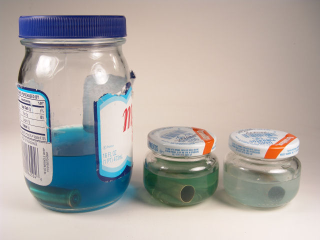
The first step is to be sure to use carefully cleaned laboratory glassware as shown in one of the attached pictures. The next picture, titled "test coupons" shows the results of an overnight soak at room temperature (64.57 degrees F) in a very concentrated solution of the special chemistry that was tested. The last picture shows the two winning coupons.
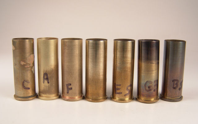
The cupons are spent 44 magnum shell cases, so such a test is likely not possible in the UK or OZ, but it is entirely possible on my ranch. The "control" coupon is polished about halfway up to the neck with #1 steel wool. The test cupons were prepared in the same fashion. All coupons were immersed in the test fluid.
Now, lets look at the results: I will proceed from left to right and each cupon is coded except for the test control one in the middle
- C: The household Chlorox cupon was slightly darkened and severely corroded. Bad.
- A: Parsons Household Ammonia left a finely etched, very attractive surface but does not look aged.
- F: Miracle Grow fertilizer, 10-30-10, and left a slightly darkened, very lightly etched surface. Still not a winner.
- (Middle) Control Coupon - all the test coupons looked like this in the beginning.
- ES: Epsom Salts solution slightly darkened the brass to a bronze-like finish, but still no winner.
- GB: Birchwood Casey Products instant gun blue. This resulted in a beautiful, glossy black transparent finish, even though the bottle warns that it will not work on non ferrous metals. It's active ingredient is selenium dioxide.
- BS: Produced the clear winner in the race. This involves some very special chemistry and I am thinking of patenting this development with exclusive sales rights, and the cost will be - awwww, I can't go through with this!!! It is just common baking soda mixed in about parts with water. Most of the soda will not dissolve, but be sure to use enough soda to cover the part.
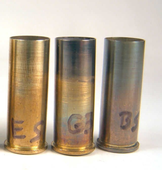
The last picture shows the two most interesting coupons, GB and BS. I don't think the camera does justice to the beautiful black instant finish that is accomplished by swabbing the part with a little of the Birchwood Casey instant gun blue (GB). This finish took about 10 seconds to develop and then I simply washed it off with water. It also works very well on steel, which is actually what it was made for. Handy stuff to have around and it does a lovely job on cylinders, etc. The winner, though, for ageing brass is the baking soda (BS) solution of about equal volumes of baking soda and water. Baking soda is not totally soluble in water at this concentration, but the trick is to have enough soda to cover the part after the soda has settled out in the solution. The end result is a uniform, lovely brown brass look, just right when compared to old brass. It is a good thing, too, as this was the last coupon I tried. That about covered my exotic chemical storehouse. I was going to try a sulfur solution next but there does not seem to be a need to do this. All of the samples were soaked overnight except for the test cupon and the gun bluing cupon.
So that is it. Instead of polishing brass we can now age it.
Bert
Thanks Bert. Gotta get me some of that thar gun blue, provided it don't attract unwelcome attention from the boys in blue...
Question:
What are typical compression ratios for small IC engines? Does it vary between two-stroke and four-stroke engines?
Answer:
This one opens a can of worms. First let's dispose of the 4-stroke versus 2-stroke part; the answer being "not at all, sort of". The "not at all" bit is because the compression ratio required is related to the fuel used, not how it is inducted, burnt, and exhausted. The "sort of" is because some folk, having thought about all the holes in a two-stroke cylinder, perceive that a difference in compression ratio must exist between the two types of engine. With both valves closed, a four-stroke will begin compressing the mixture as soon as the piston rises from BDC. With a two-stroke, actual compression won't start until the exhaust port closes, which can be as late as 70 degrees ABDC. So what's the deal?
Well, as it turns out, engine designers and reviewers, when dealing with two-strokes, generally qualify "compression ratio", saying "Effective Compression Ratio" when they are taking port closure into account. Plain Old Compression Ratio is the same as measured for four-strokes, and that is the geometric compression ratio, calculated as:
| Geometric Compression Ratio = | Swept Volume + Head Volume |
| Head Volume |
Swept Volume is the piston area times the stroke (the "displacement")
Head Volume is the volume of the combustion chamber with the piston at TDC.
Aside: As if this were not confusing enough already, people often refer to the "Capacity" of an engine when they mean the "displacement"—and respected engine reviewers are as much to blame as any for this confusion. The value on top of the dividing line in the equation above is the "Capacity". IE, the total volume above the piston when it is at BDC. The figure quoted by engine manufacturers and builders however is always the "Displacement". IE, the volume described by the moving piston (Pi times the piston radius squared, times the stroke). See? I said it was a can of worms! End of Aside.
So back to compression ratios. Using the geometric compression ratio—which I'll just call compression ratio (C/R) from now on—makes the calculation relatively simple. You can ignore where the exhaust post closes on a two stroke, or where the inlet valve closes on a four-stroke, and just use a bit of math. Providing, that is, that the head shape is flat, which it seldom is! If the head shape is not flat, life gets more difficult. Engine reviewers of any worth measure this using a tiny, calibrated burette which they use to fill the head with low viscosity fluid through the (removed) plug. With the piston at TDC, the amount released from the burette into the head represents the head volume to a reasonable approximation (imagine the problem posed by slanted plugs, air pockets, etc). Or, you can use some simple math to guesstimate the volume, because as we shall see, we've got a fair latitude in this area.
As to the C/R, it all comes down to fuel. First, let's consider "gas" engines. These were made with the C/R as low as 5:1 and as high as 7:1. That was for the old leaded gasoline, but substitution of unleaded does not seem to make much difference. For methanol based fuel (glow plug engines), the typical value is 7.5:1, rising to 10:1 at the absolute extreme. A 1955 analysis in Air Trails indicates that the average is about 8:1 and I have no reason to believe this has changed. Compression ignition engines (aka "diesel") are generally variable—right down to the point where piston and contra-piston clap hands, although practicality generally intrudes first! A rule of thumb says that the typical diesel mix (see Q&A #1) will go bang at a C/R of around 18:1.
For several reasons, C/R is one of those parameters where more is not necessarily a good thing. First, the work done compressing the cylinder content requires power, so as little as you can get away with might seem a good thing. Next, the fuel/air mix needs to begin burning before the piston reaches TDC. But we don't want the pressure build-up to be too great before the piston reaches TDC (more power loss). Then there's ignition enhancers to think about. Glow engine fuel generally contains some nitro-methane (apart from "FAI" fuel which cannot contain nitro). This advances the point at which the mix begins to burn. Dave Gierke's book on two-strokes relates a tale of how he was running mid-field at an R/C pylon race, when he accidentally tanked with FAI fuel and suddenly blitzed the opposition, setting a top score for the meet to that point (the others were running the "regulated" nitro fuel). Reasoning that this was because the nitro-less FAI fuel was better suited to his engine C/R, he reduced the C/R by adding a head shim, then set an even faster top score using the regulated nitro fuel. See? Matching the C/R to optimize the ignition point to the fuel is more important than achieving a high C/R.
Increasing the compression ratio, or the nitro content, has the effect of advancing ignition. In the extreme, the mix will burn too fast and too early. However, because of the inertia of the crankshaft, the expanding gasses will still be compressed, robbing you of power and stressing the drive train. In the extreme, the mix will detonate. This results in forces that force the lubricating film out of the rod ends, producing a "click" as the metal bits come together. The piston crown is also subjected to extreme heat and pressure. On the other side of the curve, too little compression will result in a retarded combustion (if you can get it running at all). This means that the charge is still burning as the exhaust opens, so you loose power and have a very hot exhaust.
To summarize the answer to the initial question, the figure quoted is the geometric C/R which ignores porting and lets us design our 2 and 4 strokes to get the C/R in the ball park for the fuel/ignition type. On average, two-stroke glow engines run a C/R of about 8:1. Ignition engines operating on gasoline will be lower, say 6:1, and compression ignition engines will need to get up in the region of 18:1.
Question:
Where can I buy ether for diesel fuel in the USA?
Answer:
For all the good and bad reasons mentioned above, buying ether over the counter from chemical suppliers is no longer an option. But pressure pack cans containing a mixture of ether and acetone (plus some green-house friendly propellant gas) are available from trucking and tractor supply outlets such as John Deere. If you have an account with them, Grainger also has such a product. The hard part is decanting the can contents. Now I stress that I have not done this, but pass on the following for what it is worth. Remember ether was once used as a medical anesthetic and tended to produce rather unpleasant side effects. Taking sensible precautions is YOUR responsibility—I prefer to go through the hoops of obtaining liquid ether from friendly pharmacists!
Go outdoors, invert the can, point it down-wind, and vent off all the propellant. The liquid that remains in the can after is stops going hisss is what you are after. Now take a manual can opener to the can base and carefully pierce the can, partially removing the base until you have an opening you can use to pour out the content to a glass, stoppered bottle. Read the can to determine the percentage of ether by volume in the fluid and allow for this when mixing your fuel so the ether content is up to where is should be. Don't worry about the acetone. It s not a good "dope" for diesel fuel, but at least it does no harm (see FCB Marshall's article for details on dopes).
Question:
Why doesn't the contra piston go up and down with the piston when the engine is not firing? Or does it?
Answer:
Experienced "diesel" operators may think this is a lame question, but it really is a good one that must have puzzled more than one person, new to model compression ignition engines. First, the contra piston is lapped to be a firm press fit in the bore so that it forms a gas-tight seal to contain the combustion pressure. But, I hear you argue, the piston is not a press fit and it obviously provides a gas-tight seal too, or we'd not get any compression in the first place! This is correct, but remember that the piston is generally moving all the time, so the period for which it is at required to hold back maximum pressure is very small. If you slowly turn the engine to bring the piston to top dead center (TDC) and leave it there, compression will gradually die away. How long this takes varies and can be viewed as a measure of how good the piston/liner fit is. An early British manufacturer once boasted that their engines would maintain TDC compression overnight, or they'd give you your money back! This is actually a bit extreme and engines where the compression bubbles away in a few seconds can still be strong runners.
That said, I have seen (and repaired) an engine where the contra-piston happily slid up and down with the piston. The owner had "lapped" it because he found it was too tight and so was hard to adjust with the leverage available from the compression screw. This unfortunate condition is rare, but not unknown and his fix was correct—he just went a bit too far, which is easy to do when making parallel sided contras. Although I did not test it, he reported that amazingly, the engine still ran, though badly.
The fix was a new contra, made to the "DCO method". The good/useless margin on the diameter of a parallel sided contra-piston is under five tenths of a thou (about 0.01mm), so it does not take much effort to go from too big on one trial fit, to too small on the next! In contrast, the DCO contra with its very slight taper provides considerable latitude in achieving a workable result as you are sneaking up on the fit with plenty of indication as to how the lapping is progressing. The thin walls compress to provide an adequate length of contact area, with no leakage. If you spot oil emerging around the compression screw thread when the engine is running, you know that your CP is leaking.
Back to the original question. As a rather obvious side effect of being a press-fit, the contra-piston won't move unless pushed hard. The comp screw pushes it down, and pressure of the compression pushes it up. Frequently, the fit will be so tight that merely compressing air will not provide enough force to move the contra up when the compression screw has been backed off. While air is compressible, fluids are not, so some fuel added to the cylinder may increase the effective pressure enough to move it with that satisfying snap of metal to metal movement. Sometimes even that is not enough and an actual bang of ignition is needed. Then there are diesels where the contra tightens up after the engine starts to the point where not even the pressure of ignition will push the contra back up if the screw is loosened. This is genuinely too tight and a spot of additional, judicious lapping is called for, but be careful—this is a job best tackled by engine builders, not mere owners.
I can't leave this topic without mentioning the divergent paths in contra-piston design followed by a few of the US engine manufacturers (notably McCoy and OK) in the use of a high-temperature "O-ring" as the means of achieving the required gas-tight seal, while ensuring easy movement of the component without the need for precision lapping, or selective matching of contra-piston to individual cylinders. On the other side of the Atlantic, this was frowned upon, perhaps through the Not Invented Here syndrome, although one British manufacturer (FROG) did give it a go, if only briefly. There is actually not a lot wrong with this idea, although purists will say such engines "lack feel", and point out that O-rings degenerate and the owner will be forced to replace the ring a couple of times during the next hundred years, with the potential problem of obtaining a suitable replacement. I have to confess to being firmly in this camp myself. I know from experience that engines, or glow to diesel conversion heads made using this method are quite sound and effective, but to me, they just don't feel right.
Question:
What is the minimum machinery and tools I need to start making my own model engines?
Answer:
My good friend and mentor, the late Roger Schroeder covered some of this ground in his paper, Building A Model Airplane Engine that Runs. I don't disagree with anything Roger says, but times and circumstances change and since Roger is no longer with us to update his work, also read Kitting Up To Make Model IC Engines, Part 1 in the Design Section.
Question:
How much nitromethane should I use in my glow plug engine fuel?
Answer:
This is a case where more is not always better. In fact, "none" might be the right answer (see Dave Gierke's story)! Glow plug engines run on a mixture of oil and methanol (see the How do glow plugs work FAQ for why methanol and glow plugs go together like peas and pods). Nitromethane is added to effectively advance the ignition point, just like moving the points did on old spark ignition engines. There is an optimum point for starting the cylinder mixture burning, such that as the piston reaches top dead center (TDC), we are achieving close to the full combustion, resulting in maximum effective pressure pushing the piston down on the power stroke. If ignition occurs too late, the mixture will still be expanding when the exhaust opens and so we are robbed of potential return from the burn. If it ignites and burns too early, some of the pressure will try to turn the engine backwards. This probably won't happen due to the flywheel effect of the prop, but again we loose potential power, and may cause damage to the engine.
The point at which the mixture starts to burn, and how quickly it burns depend on the compression ratio of the engine, the characteristics of the fuel, the shape of the combustion chamber, the angle of the dangle, etc, etc. Compressing the mixture in the engine cylinder does add heat, but takes work which subtracts from the power output. So a low compression ratio might be good, except lowering the compression effectively retards ignition, and as we saw above, late (retarded) ignition means we are not getting the most from combustion.
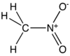
If you look at the chemical formula, or molecular diagram for nitromethane, you see lots of hydrogen and oxygen. Nitromethane itself has a rather low calorific value; about half that of methanol. That's one reason I smile (as a way to hide my grinding of teeth) when I see the Great Uninformed advertising "Nitro Engines". I guess they equate nitromethane to nitroglycerine and think it must be potent stuff. It's not. It just releases components which help advance the timing and so make an engine with a low compression ratio start ignition at a more optimum crank angle.
As to just how much is right, the late Duke Fox published a test in his "duke's mixture" info-mercial column that appeared in Model Airplane News in the late 1980's. With the sole proviso that the glow plug used should be new, or in good condition, we recommend Duke's method for optimizing the nitromethane content of glow fuel. For the adventurous, if your test suggests that NO nitro is the right amount and head shims allow you decrease the compression ratio, try that and see if the engine now wants some nitro, and if this results in more static RPM on the same prop.
Question:
How do glow plugs work?
Answer:
Glow plug engines have been called "semi-diesels". This is because compression of the air in the inducted fuel/air mix causes heating which raises the mixture towards its flash point. In rare cases, glow plug engines will achieve self-ignition through this effect, but that's thankfully rare and in normal cases, we need to apply an external source of heat to make the mix go bang. This is achieved by passing when an electric current through the glow plug coil. Just like a toaster, or electric bar heater, the resistance of the coil causes it to heat up and that ignites the fuel/air mixture. Then we take the battery (current source) away, and magically, it all keeps running. Why, you might ask.
The simplistic reasoning is that the heat from combustion is retained by the coil and that the coil, despite being sprayed with a rather cold mix of new fuel/air mix, remains hot enough to start the new charge burning. As usual, every question has a simple explanation which is almost inevitably wrong!
Yes, retained heat in the coil is a factor. So is the heating of the fuel/air mixture due to compression as already mentioned. But so is the catalytic action of alcohol in gasious form and the element, platinum. The wire used for the coils of glow plugs is a rather special platinum alloy. Older folk (we are dwindling fast) may remember the "majik gas lighter" used to ignite natural gas on cook-tops. This was just a wire wand with a wooden handle and a little coil at the end, which when placed in a gas stream, leapt to red heat and ignited the gas. No battery, nor any source of electrical current was needed. That's the catalytic effect in action, and that is also taking place in our glow engines.
Saying which of the three effects is most important in keeping our glow engines running after the current is removed is difficult, and a bit controversial. I know from actual experience that heat caused by compression alone can do it as I once hald a mode with a Fox 35 stunt engine that started from a casual flip without any battery attached. But's that's the exception and the compression ratio of a glow engine is about half that found in a "diesel" (more correctly, a "compression ignition engine").
Retained heat is important too. It's retained heat that can cause an engine to "go lean". It's like this: something demands more power from the engine, perhaps a sudden flight load. As it makes more power, it generates more heat. When it makes more heat, the plug element gets hotter and the ignition starts occurring sooner. if the motor has a little extra heat added because if being new and creating friction, or because the weather is hot, or because the fuel has too much nitro, or because the glow plug retains too much heat, the motor can come up to a critical point at which the ignition starts too soon. The common description is "it's gone lean on me", and the trigger is retained heat.
Then there's the coil alloy and the exothermic (heat releasing) catalytic action. Take my word for it, a glow plug with a coil containing no platinum will not do the job. As to how important calatyc action is, consider a "bad" plug—one where the element has been compressed up into the recess. This reduces the effective area of the coil exposed to the fuel/air mix, and to catalytic action. Such a woeful excuse for a plug might start an engine, but when the current is removed, the engine will sag, and may stop altogether. On the other side of the coin, a glow plug can break in flight and provided the coil is not injested, the engine will continue to run at full power. Starting it again though, is impossible.
As I said, it's hard to rank the three factors which keep a glow plug motor running after removal of the current. Which is the greater contributing factor, I'm not about to make a call on. I've been wrong once before in a long life and don't want to take the chance of being so again!
Question:
What is a "De Sax engine"?
Answer:
Before going into the technicalities, let's clear up the common misconception that the funny name must be the surname of a French inventor! The correct term is desaxé (one word, no Capital, accent optional) and while it is French, it means "unbalanced". As applied to engines (IC and steam), it means that the axis of the cylinder is offset from that of the crankshaft. While this makes balancing the engine rather difficult, it can have a number of beneficial effects. For more detail, see the Tech Tip in the August 2004 issue of MEN.
Question:
What are the main types of metal casting procedures? How does the metal get into the mold or die, and how can I tell one type of casting from another?
Answer:
What, if any, is the difference between die casting and permold casting? And while we are at it, how do die casting and gravity die casting differ, if at all? Then what about sand casting? Some are terrible and some are fantastic. What's going on here? Australian engine maker, David Owen, knows a thing or two about the subject, having worked on a number of proejcts with the late Gordon Burford—a master of the gravity die casting process—so we'll hand over to him for the explanation.
CASTING QUESTIONS
There are many forms and ways of casting metals. However, all rely on one of two means of getting the molten metal into the die or mold.
- Gravity.
- External pressure. This could be provided by air in the case of a casting done in a porous or vented die; it could be provided by steam; it could be provided by the molten metal itself, forced into the cavity by mechanical means.
The common forms of die or mold casting and the means of introducing the molten metal (melt) are:
SAND CASTING
A pattern of the part to be cast is encased in a casting box filled with sand, then removed to leave a cavity.
The resulting mold is porous and the melt is generally poured in and flows into the cavity under the influence of gravity. Some sand casting is undertaken under vacuum, or external pressure.
Sand castings are generally recognisable by their stippled surface and lack of sharp definition. However, modern sand-casting techniques, using specialised oily sands and bonded sand, furane or foam cores can be very accurate and well-defined.
Earlier engines, such as the Australian Whirlwind had simple sand-cast iron cylinders, whilst much later OPS and Rossi engines used very sophisticated sand-casting techniques. The original Fox 59 (AMA Museum) and a few of the specialist rear-exhaust Schneurle 29/36 Foxes from the '70s were sand-cast. The 35 Stunt was not.
GRAVITY DIE or
PERMANENT MOLD/PERMOLD (USA)
This is a metal cavity die, machined from cast iron generally, but could be brass or even aluminium. Precise metal cores are used in most cases to result in a hollow (cored) casting. Generally, gravity and less frequently, external pressure (steam or air) could be used to introduce the melt.
Gravity die castings can have good definition and generally have a much smoother external finish than sand castings. The early Fox 29/35 Stunt engines were gravity die-cast, as were all production Burford engines, with the exception of the Taipan 40. All PAW engines were and are still gravity die cast. It is not easy to cast thin sections such as fins by this method. Gordon Burford's gravity castings were exceptional.The 2.5 and 3.5 Goldhead Taipan glows were probably some of the finest examples of gravity die-casting .
The term permanent mold, or permold, comes from the USA and is related to the fact that the existence and assets of a corporate entity are vested primarily in its tooling and specifically in any dies or molds used to produce a saleable product. In order to close down a corporate entity, either voluntarily or as a result of forced closure through bankruptcy, these items must be destroyed. Hence the term permanent mold. In other words, as long as the tooling/dies exist, the corporate entity exists. Some items might escape, but basically this is the reason we don't hear of people in possession of the original dies for many older American engines. I don't know whether this regulation still applies in the USA.
PRESSURE DIE-CASTING
Obviously this term could really be applied to some sand casting and gravity die casting procedures, but pressure die casting generally refers to the introduction of the melt under mechanical pressure into a large metal die, which may contain multiple cavities. These dies are machined from pre-hardened steels and are capable of producing many thousands of castings. The die is opened and closed mechanically, the castings are ejected by force and generally have very precise definition and extensive detail.
The dies are very expensive to make, often requiring extensive hand finishing. Once set-up and running in a large die-casting machine, the production of castings is very rapid. As a result, pressure die casting is only suited to very high production requirements. The casting itself, whilst accurate, does not possess the same physical strength as sand and gravity casting, particularly when those methods are followed up with specialised heat treatment.
With the exception of the Fox engines previously mentioned, all Foxes are from pressure die castings. ED, FROG, and Davies Charlton engines, the Taipan 40, Forster, most K&B and all Johnson etc are from pressure die castings.
HOW DO YOU TELL THE DIFFERENCE BETWEEN GRAVITY AND PRESSURE DIE-CASTINGS
The latter will always have crisper definition than the former. There is often evidence of die removal pins, such as that exaggerated in the Deezil. They seems to have a smoother, hard appearance to the surface. Unless tumbled or otherwise polished, the colour is duller. Finally, any flash is much thinner and sharper.
The reason for the flash being sharper is that any leakage from poor gravity die closure is not of great importance, but where high casting pressures are involved leakage and subsequent flash must be absolutely minimised as the casting will look awful and the extra work to remove the flash becomes onerous with the production volume involved.
INVESTMENT CASTING
This is an extremely old technique, originally called 'cire perdue', or lost wax. This method was originally used thousands of years ago to cast bronzes, typically statuary. A sacrificial wax pattern was encased in an outer matrix, the investment, then removed either by burning or steaming. The melt was cast into the resulting cavity.
Modern techniques involve the use of wax or foam patterns, usually encased in a matrix of specialised material made from cristabolite and gypsum. When mixed with water, this hardens and becomes a pozzelanic substance. Concrete is a pozzelanic substance too and both, when hardened maintain the original water content.
The investment can be applied to the wax in a number of ways, the most common being sprayed on the wax in multiple coats to build up a sufficiently strong layer of material. In the case of jewellery and model engine parts, the waxes are often immersed in a special flask containing the investment. When hardened, the coatings or flasks containing the wax patterns are placed in a burn-out furnace, which initially melts out the wax and drives out all water as steam, then carbonises any remaining vestiges of the wax. The end result is a porous mold containing a cavity conforming precisely to the original wax. It is this porosity which facilitates the flow of molten metal .
The melt is poured into the mold and flows into all extremities either under the influence of gravity, or air pressure as the result of an applied vacuum.
The metal casting thus formed in the mold is allowed to solidify, after which the mold matrix is broken away by thermal shock or abrasion (sand or grit blasting). So precise is the mold, that the finest detail can be reproduced. In the case of model engine crankcases, this could even extend to tapping-size holes. Complex coring can minimise subsequent machining operations.
Investment casting can be a slow, multi-faceted process and in the case of model engines is generally confined to small production replica engines, where the duplication of complex original details is desired, and cannot be otherwise achieved without the prohibitive cost of pressure die casting. Irvine were one of the few larger manufacturers to use investment-cast crankcases and both Irvine and the earlier ETA engines used investment-cast cylinder sleeves.
Aluminium investment castings tend to have a light, oxided finish as cast. This is often removed with subsequent glass-bead blasting, which imparts a soft natural finish at the risk of slight loss of definition.
Depending on the specification of the alloy being cast, sand-cast, gravity and investment-cast aluminium castings respond well to subsequent heat treatment. This can raise the tensile strength considerably and improve the surface finish during machining.
David Owen, Wollongong, NSW Australia. 14th Feb 2013.
Question:
How do I wire up a "sparkie"?
Answer:
Once upon a time, every modeller know this just about as well as they know their own name, even if they'd never done it. Even better, you could cycle to your local model store and but all the bits required over the counter, and get free advice into the bargain, not to mention that ready advice existed on every flying field. Today, it has become a bit of a mystery, and making a spark ignition engine run the way nature intended is a bit of a chore, and a thrill. For details of ways old and new, visit our How To Wire Up a Sparkie page.
Question:
I have seen on your site and other sites references to 2 cycle engines running a 4-2-4 pattern. A four cycle, two cycle, four cycle. How does that work? Don't you need a geared camshaft to be able to run 4 cycle? I am obviously missing something here. Any help clearing the fog would be appreciated.
Answer:
Easy to see how the "4-2-4 break" can be confusing to the uninitiated. In this case, we mean 4-2-4 CYCLE, not stroke, although the terms "stroke" and "cycle" are generally taken as synonymous and the difference in this case, is a tad semantic. As our questioner says, the terms 2-stroke and 4-stroke imply the number of movements of the piston required to complete a suck-bang-blow sequence. The "4-2-4" applies to 2-stroke engines as used in control line (C/L) aerobatics (aka: stunt) and is essentially a way of achieving a constant speed, airspeed that is, not engine speed, while flying the pattern.
A 2-stroke engine operating at or near peak RPM has a distinctive, high-pitched scream. If the needle is opened to richen the mixture this changes to a lower pitched growl. The reason for this is because the mixture is so rich that the engine fires only on alternate strokes, using the alternate strokes to purge the cylinder. We term these two conditions 2-cycling and 4-cycling and the "4-2-4 break" refers to the ability of the engine (and tank and prop selection) to "switch" between the two conditions reliably.
To fly the set sequence of maneuvers known as "the pattern", a C/L aerobatics pilot wants the aircraft to fly at a relatively slow, constant speed. This gives the judges time to see how well the maneuvers are performed, and the pilot time enough to think! The 4-2-4 break accomplished this be running the engine in a fast 4-cycle during level flight, resulting in lap times in the 5 to 5.5 second range. When (for example) an inside loop is initiated, the model slows down, increasing the load on the prop, slowing the motor rpm. This reduces suction, hence reducing the fuel flow. The result is to move the engine into the more powerful two-cycle range of operation, restoring airspeed and powering the model through the turn.
As the model passes the top of the loop, the process reverses and the engine "switches" back to four-cycle operation with the slowed prop acting as a break to prevent speed increasing. In a maneuver like the horizontal square eight, the engine may switch as many as nine times—music to the stunt fliers' ears, giving the pilot time to position the corners, "nail" the intersection, and flatten the sides.
That is the "4-2-4 break" which today, we attribute to one of the founder Motor Boys, Mr George Aldrich. To be fair, George probably did not invent it, but he did the most to understand it, promote slower stunt, and in later years, produce engines which behaved this way, out of the box (George dubbed his GMA operation, "The Home of the 4-2-4 Break.
Achieving this mode of operation requires an engine with mild porting (exhaust opening lazily, with a decent blow-down period), a moderately small venturi, and low-ish compression. This tends to produce an engine with a broad band of stable operation and a positive but not sensitive reaction to the needle valve setting. Initially, this meant cross-flow scavenging, like the venerable old Fox .35, the engine first used by George in his Nobler design, made famous by his 1952 Model Airplane News, 2-part article titled "Stunting Can Be Smooth". Other engines appeared from time to time which gave the 4-2-4 break "out of the box" such as the Super Tigre 46 and 60, while the technically advanced modified stock engines to achieve the desired result. In modern times, work done by George, Dub Jett, and Randy Smith, and others, have produced such engines for the "pro-stunt" lobby—that's pro as in professional, who are not averse to paying professional prices for their engines.
To put some of this in perspective, let's consider a model on 65 foot lines, flying a 5.5 second lap. This translates to an airspeed of about 74 feet per second. A square loop is entered from level flight (4-6 feet off the ground) and should top-out with the lines at 45° That means the pilot has completed two "square" corners for about 50 feet travelled, taking about 600 milliseconds. Let's put it even more in perspective. The outside square loop is initiated from the same line angle of 45° with a "square" outside turn which might have a radius of 10 feet, if pilot and model are really good. The model must now travel about 24 feet before the next outside square turn is initiated so the model pulls out, inverted, about 5 feet off the deck. The time between completing the first corner and starting the second is about 300 milliseconds. Get that wrong by less than 100 milliseconds and you've either blown the maneuver with a high pull-out, or dug a post-hole. All that assumes that the model maintained a constant 74 fps speed, so I hope you now see why that speed regulating 4-2-4 break is considered so important.
Today, a tuned-pipe setup can also perform the speed regulation trick, as can modern ECL (Electric Control Line) set-ups, but it all began with George and the 4-2-4 break.
![]()
 Home
Home
This page designed to look best when using anything but IE!
Please submit all questions and comments to
[email protected]