

Editorial
The venerable DSTC servers were finally turned off on July 14. Which, coincidentally but appropriately, is Bastille Day. Based on the number of hits that arrive from a redirect at the old location on the DSTC Archive server, I expected to see a drop of traffic this month. This is one of those occasions when I'm sorry to be proven correct. Total traffic for July was just over 8GB, compared to over 10GB for June. I can only hope that those who, despite prior warnings, were entering the site through the now defunct archive.dstc.edu.au/BDU/staff/ron URL do a search that finds this text, allowing them to upgrade their bookmarks.
My return to the academic lifestyle has resulted in a bit more free time and a lot more energy to do things in that free time, like trying to recover eight years of lost email (long story; requires alcohol). Among the lost stuff is the file of news items awaiting inclusion into these pages, explaining why we are a bit short on news this month. This is more than made up for in the plethora of little bits and pieces machined for the DH Cirrus Mk I during the month and dutifully added to the series construction pages. The end is now in sight for the Cirrus, with just the cylinder head and manifolds to go (just? That head is a BIG job). Read on...
Cirrus Progress
The poor old Cirrus Mk I project has languished for the mandatory year, having gone under the bench to do the construction series for the Morton M1 that appeared in Model Engine Builder last year. But as you may have gathered from last month's Tech Tip on step turning, it's on the front burner again and a flurry of activity has seen a lot of little parts related to the valve gear completed. Read about it on the Cirrus Valve Gear page, and revisit the Cirrus Piston page the to see progress on the rings. The piston machining text has also been revised to improve correctness and clarity.
Links
Near the end of each month, I put my Webmaster hat on and check what other sites are referring browsers to pages on Model Engine News. Sometimes this leads back to a site that is worth spending a few minutes at. One from last month is called Machine Tools for the Home Shop. The author has some very definite, positive opinions regarding inexpensive imported machinery, and some nice photos of tooling bought at on-line auctions to make your mouth water.
German Precision
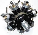
Dietmar Kolb maintains a very nice model engine web site under the name Meine Modellmotorensammlung. Naturally, the text is Deutsch, but that's what on-line translators are for, and you can always just look at the pictures. The site has pictures of both commercial and home built engines. Dieter mailed some pictures of a tiny 7 cylinder four-stroke radial built by Herr Erich Handt. These have been added to the Engine Gallery. To keep your download times reasonable, the Gallery is split into individual pages of roughly equal size. The new entry has required creation of a new one: Page 9.
Motor Boys Plan Update
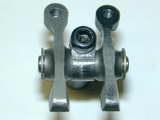
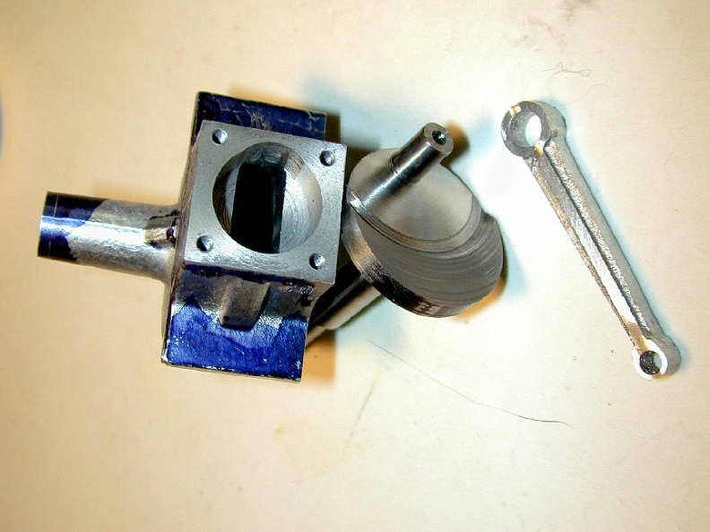
A common feature of old model engine designs is separation of the cylinder area from the crankcase chamber by a "floor" in the crankcase located just below the bottom of the cylinder protrusion. To allow full and free movement of the conrod, a transverse slot is then cut in this floor (or ceiling, depending on your perspective). I've no definitive explanation for why this was popular. Maybe the ancients thought it increased rigidity of the case, or perhaps they wanted to increase primary compression through a reduction in crankcase volume. Or maybe it was just copied from full-size motor-cycle two-stroke practice (where the previous possibilities would have some validity) and became de rigueur for a time. With the benefit of hindsight, this practice not only makes engines harder to machine, it can make them impossible to assemble!
 One such case (no pun intended
  ) is the Mancini M20 that appears on our Motor Boys Planbook. This is the only engine in the book we'd not made an example of, so the little gremlin has sat there, patiently waiting for the first unsuspecting builder to stumble across it. I guess it's poetic justice that it should be one of our own number, specifically Roger Schroeder. Roger found that with the slot and crankpin machined as drawn, there is just no way the rod can be juggled onto the crankpin.
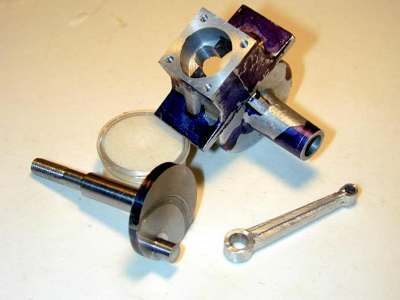 The fix required was two-fold. First, an additional slot had to be machined forming a "T" that would allow the rod to be moved further aft. Second, the length of the crankpin still needed to be shortened to about 0.250" (as drawn, it is quite long). These mods enabled the engine to be assembled, and disassembled, without further problem. Roger now plans to machine a new backplate so that the distance between the rear of the crankpin and the face of the backplate is reduced. This ensures that there is no danger of the rod sliding backwards off the pin during running. It will also improve primary compression at the expense of a little case volume. This is probably a good thing as high primary compression improves transfer and generally makes starting easier.
So, if you have our book, make a small notation on the drawings to reduce the crankpin length to 1/4", increase the backplate depth by the corresponding amount, and mill a 5/16" wide slot from the center of the rod clearance slot to the rear of the cylinder spigot hole.
Model Auction Site

A scatter-gun email arrived during the past month that announces "modelbidder.co.uk, the auction site dedicated to model enthusiasts" (at last, a piece of vaguely useful Spam ). As you can see from the URL, the venture is UK based, and to the best of my knowledge, is the second such venture of this nature to emerge. The presentation is quite "professional", with a distinct Amazon feel to it (I think they offer a tool-kit). I have doubts about the viability of such operations, as evidenced by the previous site that has sunk without trace. For the seller, why risk your potential return on a niche web site when the Big Guy (eBay) is seen by millions who are well known to pay over the top prices? And for the buyer, why spend time browsing a site where the sellers aren't? But what would I know? My endorsement would probably be the kiss of death, so let's see what praising with feint damns results in. Visit them at http://www.modelbidder.co.uk. At the end of July, they had a total of 16 items posted.
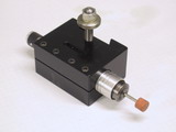
Watzit
Another new Watzit this month. And while we have no certain answer regarding what it is, you will have fun spotting the influences and unusual aspects to it's construction.
New Books and Magazines This Month
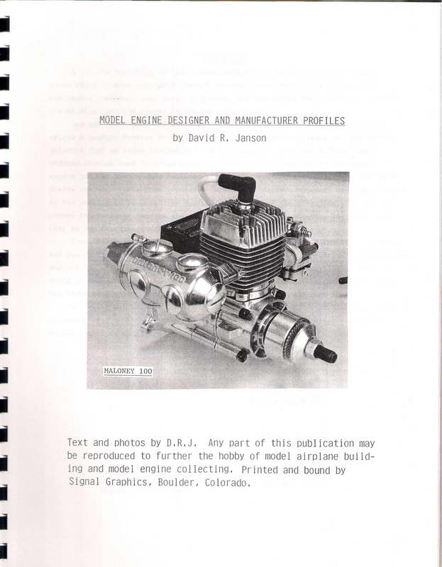
Model engine builders and collectors are great ones for self-published and "small press" books. This makes sense as the market for such publications is as small as it is passionate. The Library contains a lot of booklets of this nature and last month, it grew by one more, courtesy of a generous donation from a friend. The work in question is called Model Engine Designer And Manufacturer Profiles. It was compiled by David R Janson from a series published in the newsletter of the Denver chapter of SAM, the Society of Antique Modelers. This series, researched and written by David, spanned ten years and covered 113 subjects. The book is spiral bound, single sided, quarto size, and in place of the usual copyright page, carries an encouragement to copy and reproduce as you will to further the hobby of model airplane building and engine collecting. David deserves praise for this alone!
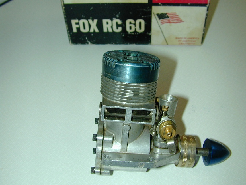
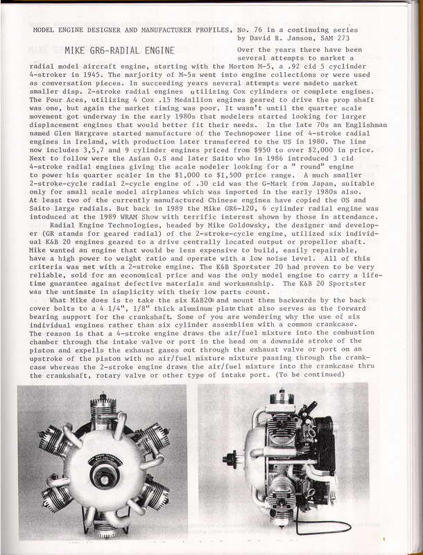 The subjects covered run from the relatively common (eg, Fox 60), through the small production run engines (eg, Sesqui), to the rare and obscure (eg, Krasnorutski Inline .60). If anything, and to my delight, the series is more weighted towards the latter than the former. Seen here is a page describing Yet Another geared two-stroke radial that I was unaware of. Time-wise, the subjects span 50 years from the late 1930's through the late 1990's. The engines are arranged in order of publication in the SAM #1 newsletter, Exhibits. But an index orders them alphabetically with the corresponding review number. The pages are not numbered, so finding an engine requires a bit of page flipping to locate the review number, but it's not awful. Each review consumes a page, sometimes two, with clear, well researched and written text, plus a photo or three. The photos are clear, although a bit "grainy". In some cases, Janson has had to resort to reproduction of magazine advertisement pictures with consequent quality degradation, but you can't really fault that.
Where can you get a copy? Sorry. No idea. As told to me, only a relatively small number were published in early 2006, and no address is provided that I can pass on. But David Janson's generosity may result in copies and excerpts doing the rounds. I consider my copy a valuable addition to The Library as a reference work and source of enjoyment.
-oOo-
Another arrival during July was issue #6 of Model Engine Builder magazine. The complete construction article in this issue is for a water hopper cooled, "hit 'n miss", farm-type engine. These are fascinating things to watch run and I really must make one someday. Other articles focus on valves and machining "full" crankshafts (see Feeney Crankshaft page for comparison). Editor Mike Rehmus continues to walk the fine line in catering to all tastes, and doing a good job of it. I always find something worthwhile in MEB. In comparison, there are issues of the ME that contains absolutely nothing that interests me. If you like model engines and don't have a subscription, you should.
Engine Of The Month: Taplin Twin Mk III
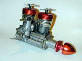
Taking David Jansen at his word about unrestricted reproduction permission of the engine reviews he wrote for the Denver SAM chapter newsletter, his first article has been scanned, OCR'd and presented in as close to the original form as I can manage. I've merely replaced the grainy B&W photo with a similarly posed one. The Taplin is an engine near and dear to me—a feeling engendered by boyhood memories of the gosh-wow factor Taplin ads in Aeromodeller raised in me. My AURORA Taplin seen here was provided by Bert Streigler who assembled this and many more from parts while acting as the North American representative for the Indian (re)manufacturer, but that's another story. Click on the picture to read the review, and if you've not seen it before, have a look also at the Prototype Taplin Twin Construction article and the Taplin Quad.
Tech Tip of the Month
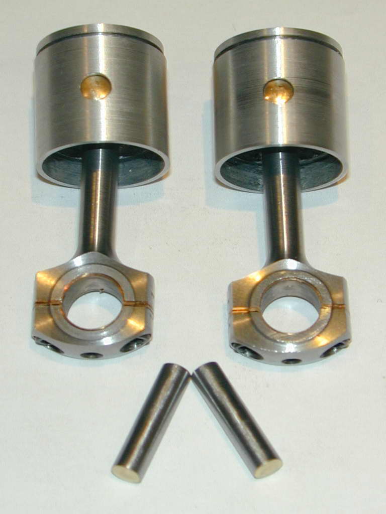
Maybe that should be "Anti-Tip" of the Month as I relate how an intended time-saver increased effort and reduced quality. The photo shows the wrist pins for the DH Cirrus Mk I. These are 0.670" lengths of 5/32" diameter drill rod (0.156"). As they are of the "fully-floating" type, the ends need some treatment to prevent them damaging the cylinder liner. The Zimmerman plans (and the SIC CAD redraw) show two options. One is to apply blobs of high-temperature silver solder to the ends, then shape it to a lightly domed section. The other is to fit brass pads and shape them. I chose the latter option, which is a common design technique, and one I've often used in the past.
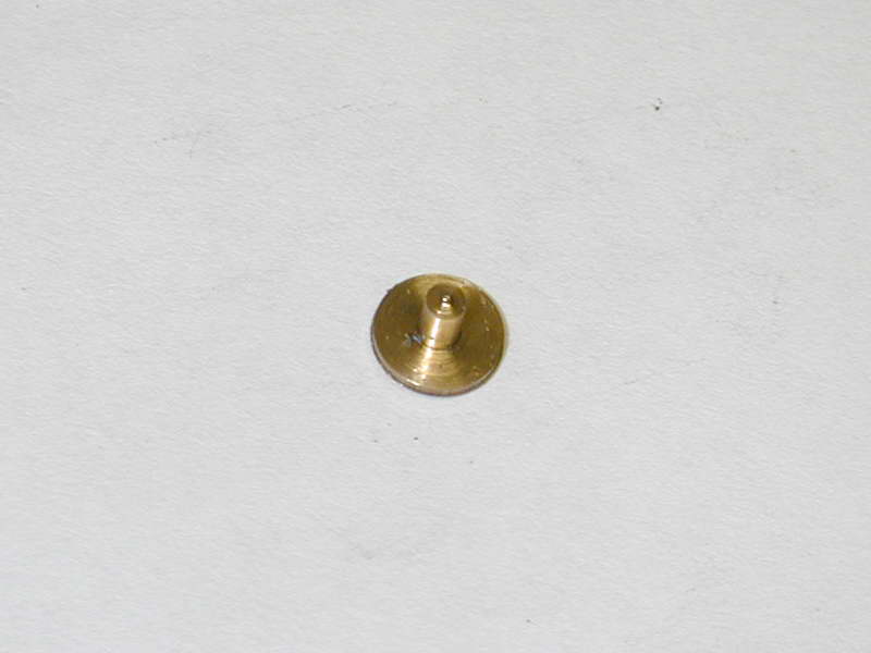
The pads are turned like little rivets with 1/16" shanks. The pin is drilled for these, sometimes all the way through, but in this case, simply a blind hole about 3/32" deep. Normally I'd fit the pads with an anaerobic adhesive like Locktite. From past experience, I know that the pads need clamping pressure applied until the adhesive cures because the assembly behaves like a little air-shock-strut where the thick adhesive acts like oil, preventing escape of the trapped air which tends to push the pad out. So the whole process of cleaning oil from the fingers and cutting fluid out of the holes and off the pad shanks, applying the glue with a toothpick, keeping your fingers off the clean surface, then clamping up the whole thing as it dries is rather, shall we say, tedious? Much easier to make the pins a force fit and avoid all the hassle.
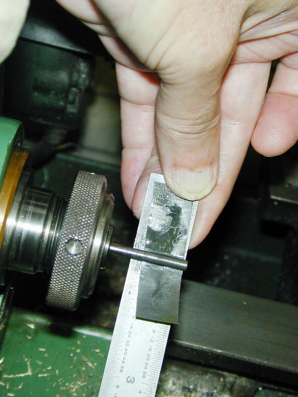 How much of a force fit? Oh, a thou or so, who knows? The 1/16" drill is not going to produce a precise 0.0625" hole anyway, so I made all the pads to a cross-slide reading that produced a satisfying fit in the test object. My drill rod stock was a very tight fit in the holes produced by my relatively new 5/32" reamer, so prior to this, all pins had been polished to a close sliding fit in the holes reamed in the pistons and rods using the time-honored 600 grit glass paper, oil, and a steel rule. This was not unexpected, but what I found next was!
Think about it. The metal can't go away, it can only go somewhere else. Either the shank of the brass pin is going to get longer and extrude into the hole in the wrist pin, or the diameter of the wrist pin is going to expand locally. Maybe the length of the brass pad shank did increase a bit, but as none of my wrist pins would fit into the pistons and rods anymore, we can certainly say the wrist pins got bigger. Measurement with a digital very-near caliper indicated the ends of the pins to be between 0.0005" and 0.001" larger than the middle. As the precision of electronic calipers of this type is only 0.0005", the problem could be even worse. Another hour of work with the 600 grit paper and steel rule got the pins fitting again. Perhaps they are even circular, cylindrical, and regular, but I doubt it. It would probably have been a better idea to scrap them and make new ones.
I've never read of this effect before in all my library of model engineering texts and magazines. The subject of "fits" in general is covered in good reference texts such as Machinery's Handbook, and Tubal Cain's Model Engineer's Handbook. Both contain tables for the various types of fit, but nothing about any side effects.
According to Machinery's Handbook, 25th Edition, Force Fits are annotated on drawings with the ANSI symbol "FN" and are categorized FN 1 through FN 3. The higher the number, the greater the interference. The reference tables indicate that for hole diameters of 0-0.12", the interference will vary from maximums of 0.0005" for a FN 1 (light drive fit), to 0.00085" for a FN 3 heavy drive fit. Even higher up the interference fit chain are the FN4 and FN5 "shrink fit" categories that require heating (or chilling) of the parts for assembly.
The Model Engineer's Handbook has less information, but is better suited to the sizes we generally work at (as is to be expected). It offers a table of fits which is almost relevant to the problem. This is reproduced in part below:
| Fit Class * | 'C' (0.001") | thou/in |
| Shrink | +0.5 | +1.5 |
| Force | +0.5 | +0.75 |
| Drive | +0.3 | +0.45 |
| Wheel keying | 0 | 0 |
| Push | -0.15 | -0.35 |
| Slide | -0.30 | -0.45 |
| Precision run | -0.50 | -0.65 |
| Close run | -0.60 | -0.80 |
| Normal run | -1.00 | -1.50 |
| Easy run | -1.50 | -2.50 |
| * For shafts from 0.125" to 2" | ||
To calculate the shaft size for a specific hole diameter, add to that diameter the constant value from the second column (the 'C' value), and the factor from the third column multiplied by the hole diameter in inches. So for a "Force" fit of our 1/16" pads, assuming a perfect 0.0625" hole, the pad shank should be 0.0625 + 0.0005 + (0.0625 * 0.00075 = 0.00005). Totaling this (and extending precision beyond the easily measurable) gives 0.06305". This agrees reasonably well with the tabular data from Machinery's Handbook. So the total interference amount should have been about half a thou over whatever the real hole size was, which is difficult to measure with this precision.
My interference figure which was probably 0.001" or greater moves us into the FN 4 or 5 region which are for Shrink Fits that Machinery's Handbook says are utilized where heavy pressures are impractical (I managed ). The text notes that the insertion pressure required in tons will be 7 to 10 times the diameter in inches.
My recommendation (note to self): don't do it! Or if you must, go for a light fit. Aluminum pads rather than brass would probably not have caused the problem to the degree experienced, but aluminum galls easily with rubbing and we don't want to introduce stray metal particles into a cylinder liner. In future, I'll avoid short-cuts, or do the research first.