 |
Westbury Whippet Project:
|
Making valves has been covered to death on these pages, although there have been minor variations in just about all cases; for example:
You might think those would be enough on the subject for one life, but there is always another approach to try in the endless pursuit of a Better Valve, or just to relieve the boredom. So for the Whippet, I decided to follow the approach that Les Stone has been using for years: fabricate them! The stem is just a length of drill rod. To this we silver braze a stainless steel disk for the head. Drill rod could be used for the head too, but stainless is probably better as it will make the all-important seating area more resistant to the corrosive gases. Before you run screaming from this herasy, look at all the valves Les has made this way and be assured, all Les' engines are runners, not show ponies (I could learn a thing or two here).
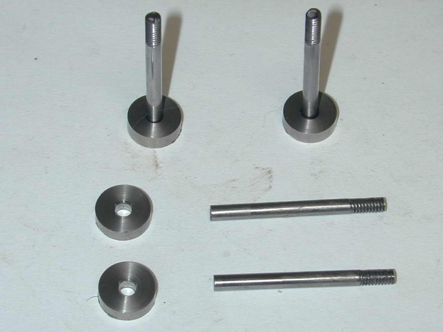 Step one is to prepare the stems and head blanks. The stems are 1/8" drill rod, threaded 1/8-BSW (British Standard Whitworth, a 40 TPI thread). The head blanks are parted off from oversize stainless rod so they are also 1/32" oversize in thickness. The stems likewise 1/32" over length, allowing for finishing to the final dimension. The hole has been drilled #32, followed by #30 to give a hole that will be about 0.003" bigger than the stem. Finally, one side of the hole has been lightly counter-sunk. This will be the "stem" side of the head, forming a pocket for the silver braze.
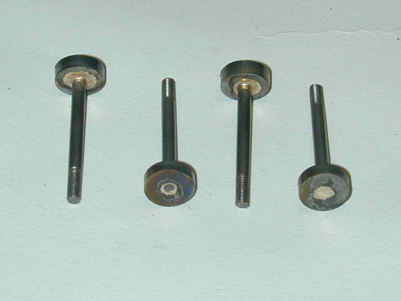 Next, the parts are fluxed and brazed, standing upright. The oversize hole allows the braze to well and truly flow around the stem all the way as can be seen in this shot where we have a nice fillet on the stem side, and clear evidencs on the "hot" side that the two parts are well and truly joined. The head will be anything but "true" in relation to the stem due to the rattling good fit of the stem in the #30 hole, but that does not matter as we will be machining it true with the stem in the next step.
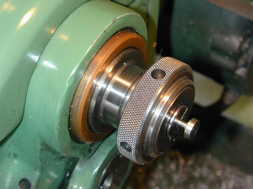 This is a place where you really need collets. It is vital that the valve seat be concentric with the stem, otherwise it has little chance of giving an adequate compression seal, especially at model sizes. So unless you have an adjustable, "Grip-Tru" type three jaw chuck, or want to clock the stem true in a four-jaw, you need collets. In this shot, a valve has been gripped with a bit of over-hang, allowing the rough head to be reduced to the finished diameter and head thickness.
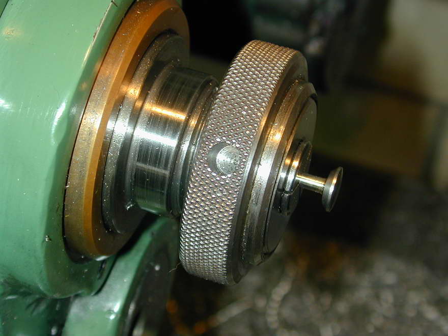 The top slide can now be set over 45° and the seat turned until the the amount of full diameter head is 0.030" long. There really is no need to true up the head on the braze fillet side as we don't want to disturb that fillet, and the diameter there is so small, any "tilt" will be negligible. The head side of the Whippet valves are lightly hemispherical, so to finish off, this is roughed with a form-tool, then finished by light application of a fine Swiss pattern needle file, followed by 600 grit aluminium oxide paper (the black kind) backed by a piece of pine, and plenty of oil. When finished, the "witness" formed by the valve outside diameter should be about 10 to 16 thou thick. Later, we will cut a slot in the hemi part of the head to assist tappet adjustment (not for grinding the valve to the seats as some think).
If you are smart, you'll leave the top-slide set over to the same setting for all the valves, and once they are done, pop the valve cages into a collet to cut a light chamfer at the same setting. The resulting "seat" in the cage should be no more than 0.020" wide on the diagonal. Even smaller will not hurt. This is an advantage of doing the valves this way. Using the "traditional" approach, the top-slide is set over the wrong way for cutting the seats in the cages, so the match between the two angles may not be precise.
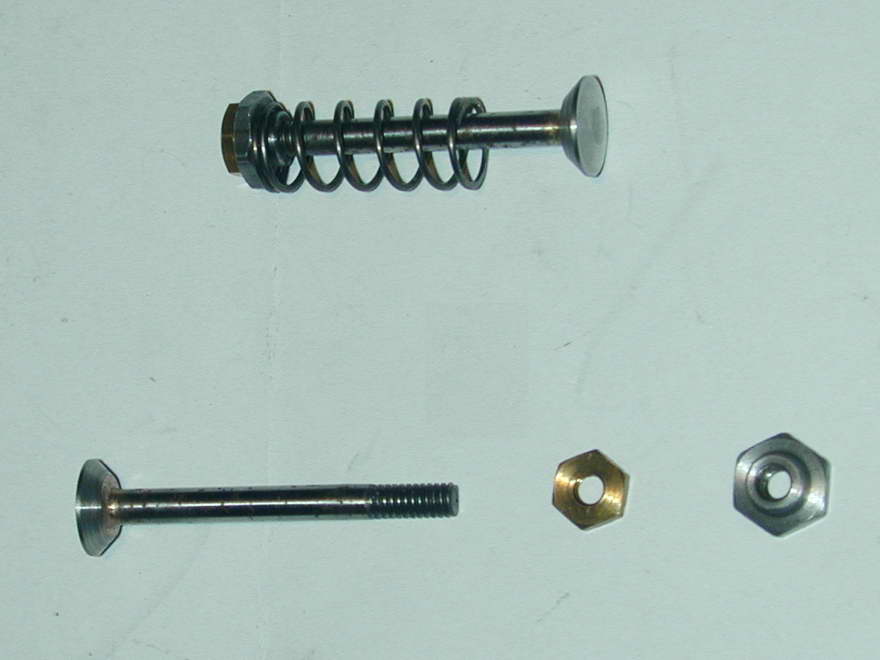 Here are the two nuts that Westbury favoured on all his side-valve four-stroke designs. The steel nut has a step that centers the valve spring. The brass nut locks the two together at the required tappet clearance setting and forms the surface the tappet hammers against as the valve comes "on the cam". The stems in this shot still need polishing, although they are free of flux, having been pickled in citric acid (lemon juice used for cooking) and cleaned with a Scotch-brite pad.
So, is it less work than the "traditional" approach? I'd give a qualified "yes". My drill rod stock was all about 0.1254" in diameter which was just too tight for the reamed 0.125" valve guides. I eventually made a special D bit reamer from the same drill rod stock to open out the holes, but even then, the stems needed polishing to get a free fit. Finally the fit is excellent and the valves hold compression very well with no "lapping" required. So I had extra work to do, plus there's the effort of hauling out the propane torch, the fire bricks, cleaning off the flux, and re-polishing the stems after brazing. It was less work, but not all that much less, and my stems will be less corrosion resistant than an all stainless, one piece valve. But Les' method has produced nice valves that seat extremely well, so I'll probably use this method again, especially when I get around to the Hodgson 9 and it's 18 valves!

|
This work is licensed under a
Creative Commons Attribution-Noncommercial-Share Alike 3.0 License. |