Model Engine Gallery Page 5
(The Les Stone Tribute Page)Last update: September 2012.


Click on the images to view them larger size.
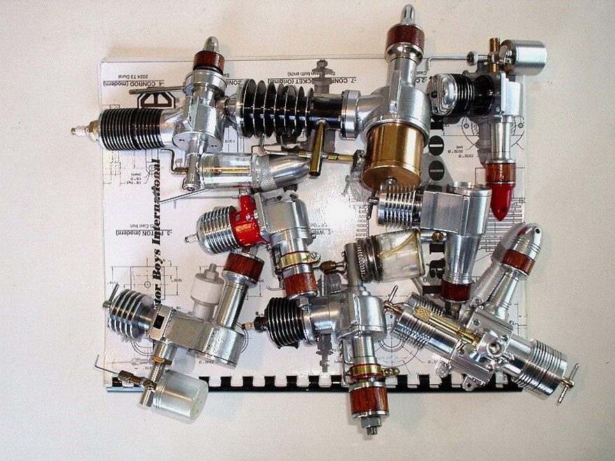
This page contains a montage of engine pictures from prolific builder, Les Stone. Les has been a great supporter of this site and hardly a month goes by when he does not provide another picture or two for us to enjoy. So Les, this page is for you!
|
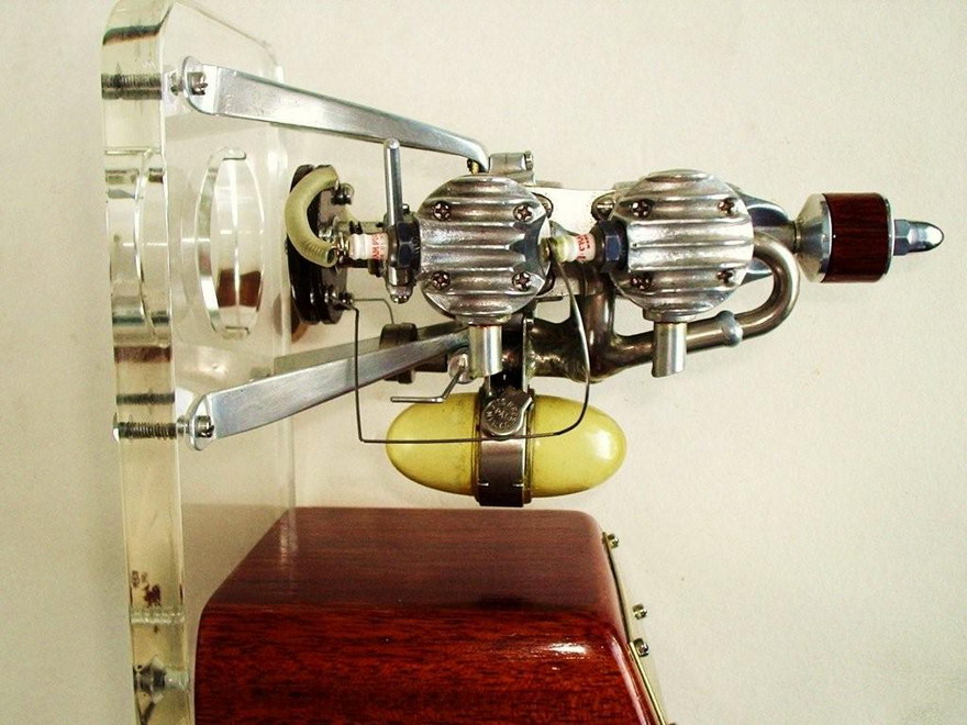
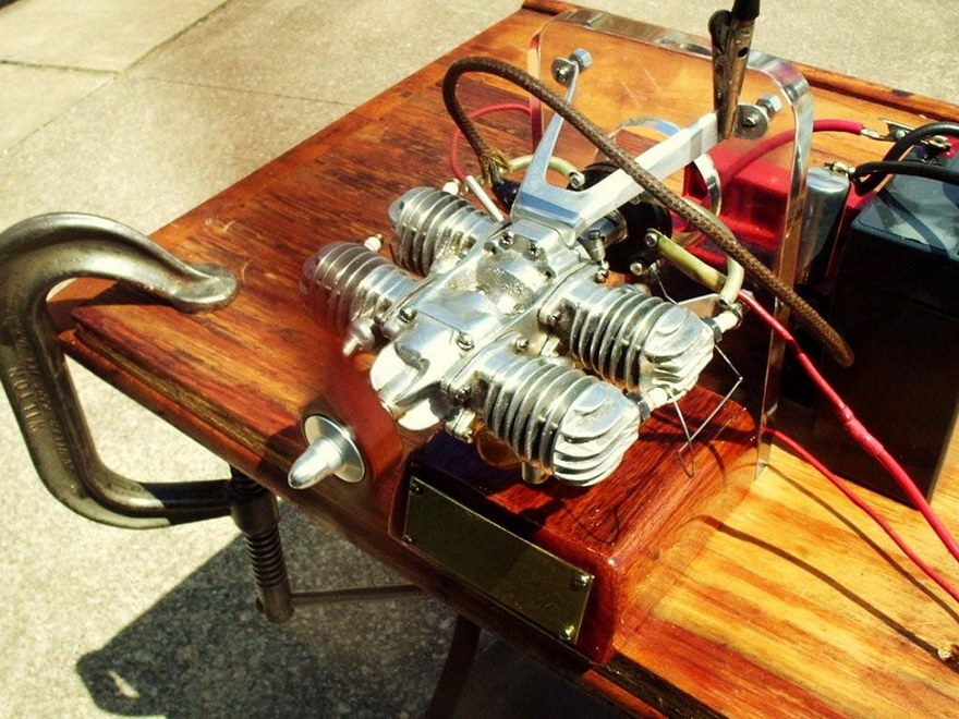
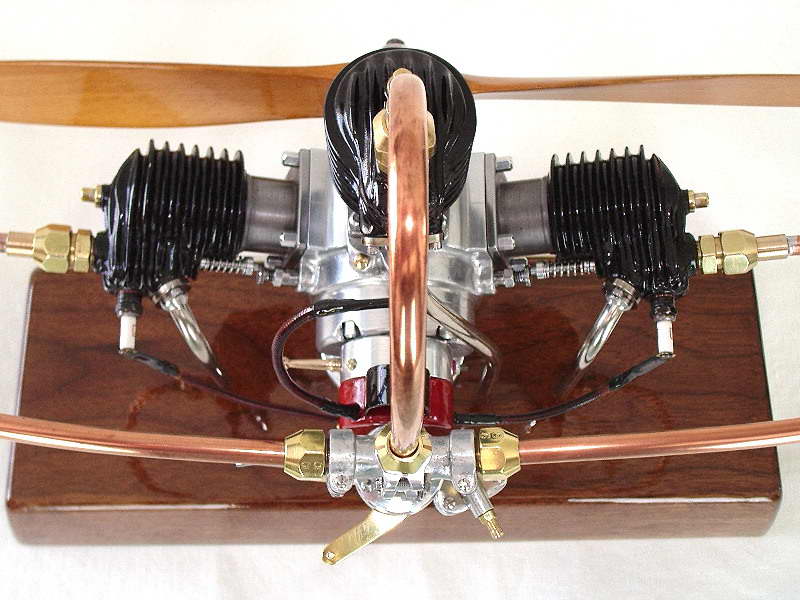
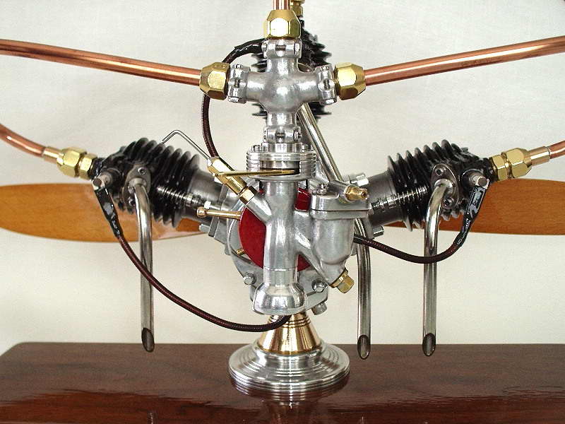
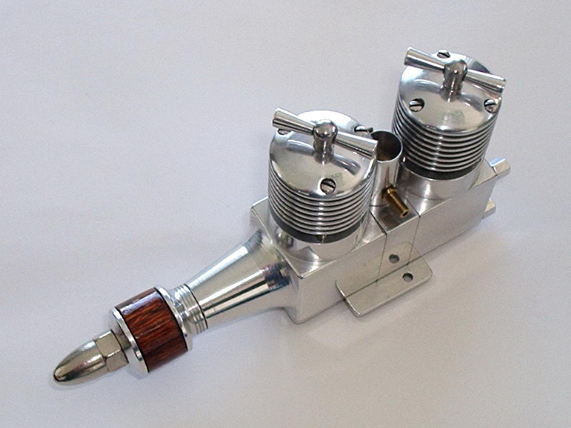
This is Les' rendition of the ELF "Goose Egg Four", a flat four cylinder two-stroke, which means it's two simultaneous firing boxer twins, arranged to fire 180° apart. The engine is fully piston ported and the name derives from the shape of the fuel tank suspended on the underside of the engine. The designer is Dan Calkin and I really recommend the book about him and his engines by John Brown, titled Dan Calkin and His ELFs (he never called them Elves). As the two twins are alternate firing, the engine requires a distributor, which can bee seen at the rear. Above the egg is a spider of piping which carries the fuel/air mix from the filtered air inlet to each cylinder. Like all Les' engines, the Goose Egg is a runner, which makes it even more amazing, after you study its construction as detailed in the John Brown book. | ||||||||||||

|
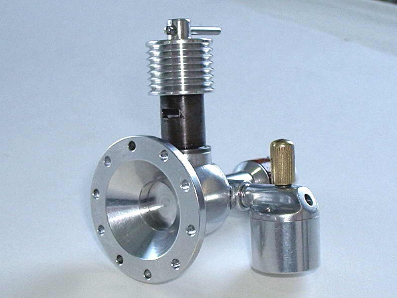
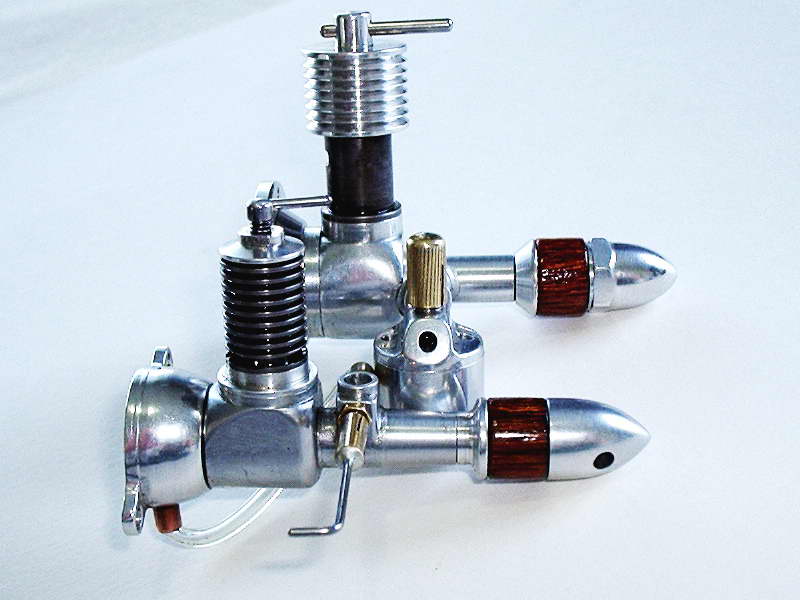
Les and I, plus doubtless many others, have very fond memories of our departed friend, Roger Schroeder. Roger did more than anyone else I can think of to foster the resurgance in model engine making through his very inexpensive casting kits. This is Les' recently completed (as of July, 2013) Junior Brown Junior, from one of Roger's casting kits, sent to Les in September, 1986, making it almost as vintage as the engine it is based on was when Words and Music for building the engine appeared in The Engine Collectors' Journal, Numbers 81, 82, and 83 of that same year. The actual Brown Jr, designed by Bill Brown, had a displacement of 0.61 cuin. For his "junior" version of the engine, Roger scaled this down to 0.199 cuin with a bore of 0.625", and a stroke of 0.650". This changed the bore/stroke ratio from 0.96 for the original, to 0.875, resulting, Roger believed, in a better running engine, small enough to make on modest equipment. Les built a Hurelman style timer for his engine, following Roger's recommendation that the standard timer was fussy and hard to make. As we see in the last shot, the engine runs just fine with it. |
||||||||||||
|
With this engine, Les completes the set of engines pictured on the original Motor Boys Plan Book. The new arrival is the 1938 Trojan Jr, a 0.192 cuin spark ignition, piston ported engine with a roller bearing crankshaft. The original engines had a complex cast iron cylinder, which Les has faithfully replicated. The Trojan Jr was introduced in 1937 and is very rare today. It featured a cast iron cylinder with a brazed on bypass cover and intake mounting flange. The completed assembly was painted a bright red and the aluminum cooling fins were shrunk onto the cylinder. The main change for the 1938 model was at addition of cooling fins to the top of the head, a metal fuel tank, and use of the new-fangled 1/4" spark plug (the '37 model had a 3/8" plug, which substantially increased the size of the engine). Les' rendition is faithful in every respect, and like all of his engines, runs just fine—better than original most likely, reflecting Les' skills, experience, and attention to detail. If you look in the background of the action shot, you'll spot the motor cycle coil Les uses to test his spark engines. This delivers a good hot spark which is exactly what you want when testing a new engine. |
||||||||||||
|
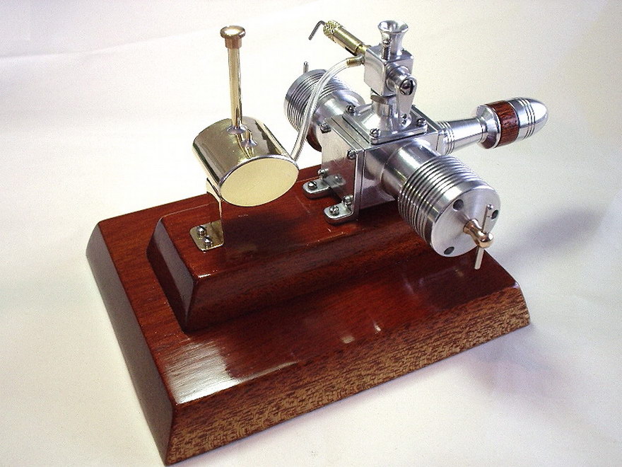
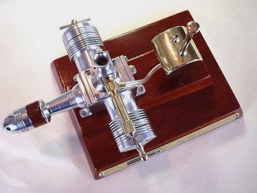
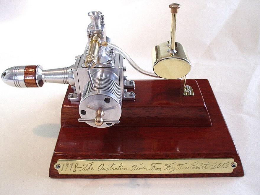
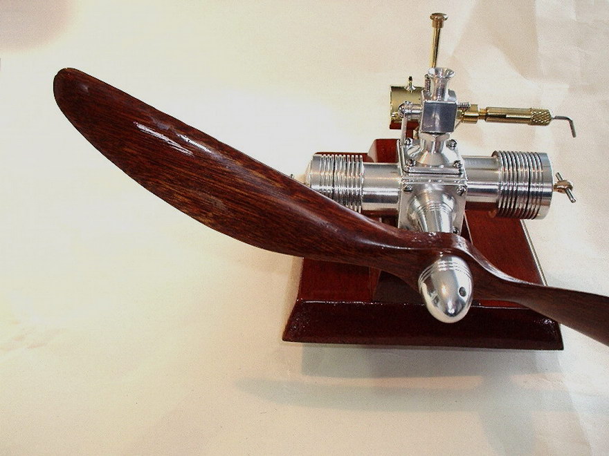
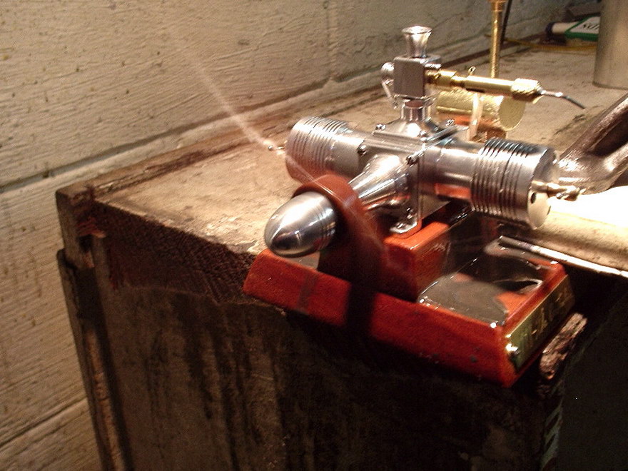
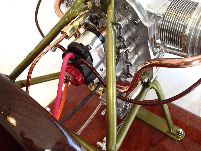
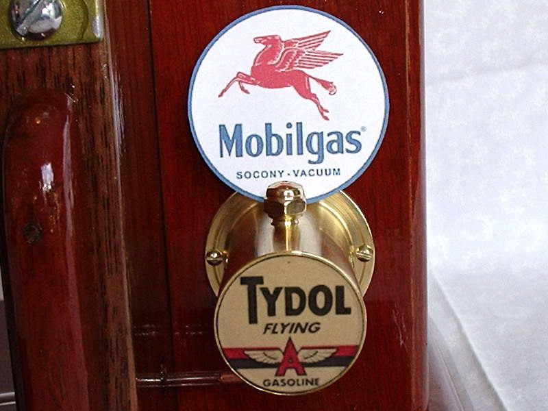
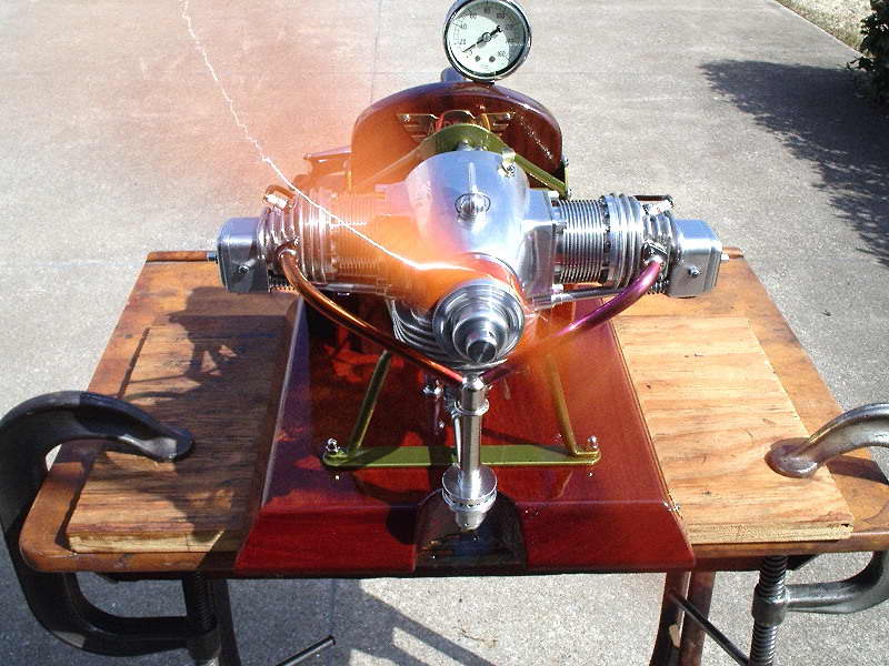
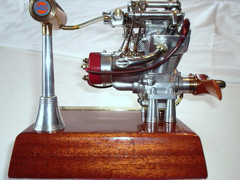
Les insists that the first order of the day is a big thank you to Don Brymer of Australia for sending photos of machining sequences he used in making his Fig Tree Pocket Twin (a picture of his twin can be viewed in Model Engine Builder Issue 27, page 9). The brass plaque on the engine's mahogany base echoes the description in the Motor Boys' Plan Book. The designer was Russell Watson-Will, who resided in a suburb of Brisbane, Australia, named "Fig Tree Pocket". Russ would be rolling in his grave right now insisting he did not design the engine, he simply copied the ideas of several others to construct it! I call it all academic, as without his work, beautiful reproductions like this and other could not exist. Like all experienced builders, Les made some changes. The first major internal change was a reduction in crankshaft diameter. The massive 0.375" central shaft was dropped down to 0.250 diameter. It was further reduced through an 8° taper to hold the drive washer, then down to the final diameter of 0.188 for threading 10-32 for the prop nut. Les liked the 10° outside taper on the headsand the recessed mounting screws. He also liked the appearance of Russ' simple R/C carburetor, so he to followd this approach, extending the carburetor venturi a small amount to incorporate a shaped trumpet/trombone effect. He did change the fin size and spacing on the cylinders giving one extra fin on the head plus one extra on the cylinder—there's always room for more cooling! Finding the design of the compression screw on the recent BJ Cacada compression ignition engine appealing, Les incorporated it into his FTPT—times 2, with bronze compression screws and 0.093 diameter stainless steel Tommy-bars pressed in. The "BJ" qualification is for the designers, namely, Chris Boll and Rob Jenkins. Les used 3-48 stainless steel, slotted philister head machine screws throughout and for the "First Run" trials, fitted his Schroeder "First Ohlsson" fuel tank, mainly because of it's equivalent size to the engine. The One Size Fits All Elf mahogany prop is 12x6-1/2, made in accordance with page 247 of John J Brown's Elf book. At the time of writing, Les is still running the engine in—slowly—as evidenced by the sludge on the mounting block. But believe me, at full song, the FTPT is LOUD! |
||||||||||||
|
With one Sugden Special in house, Les saw no need for another, but what to do with the magnificant die casting for the Sugden made by Vincet Chai Les had sitting around begging to be built? Rather than leave Vincent's casting sitting on a shelf, or in some dark drawer never to see the light of day, Les waithed for right engine to come along that would look good in this case and still be functional. This finally came along in the form of Mike Cook's "Whatzit Diesel" as seen in Engine Collectors' Journal, Volume 35, issue 200 of August 2010. The bore and stroke are 0.500" by 0.562" respectively, which works out to 1.808 cc or 0.11 cuin. The connecting rod has a center between the holes of 1.062". Mike's engine has a large outside bypass as shown in the ECJ pictures, Les opted for an internal milled bypass. After burning up four tank-fulls of fuel through the engine, Les concludes it's an absolure SCREAMER. The one unusual feature which he liked about Mike Cook's engine was the milled slot in the top of the cylinder head for adjusting the compression which was incorporated into Vincent's composite diesel. |
||||||||||||
|
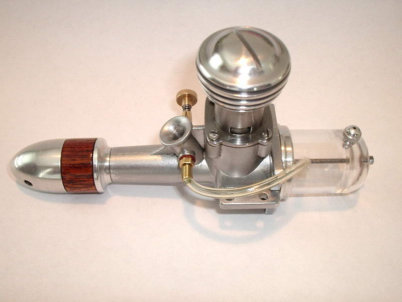
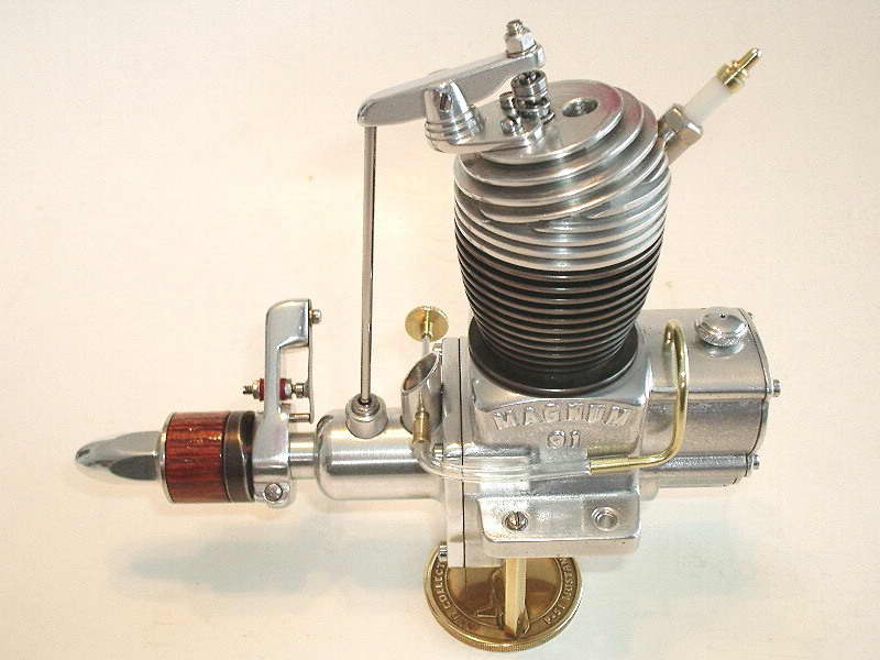
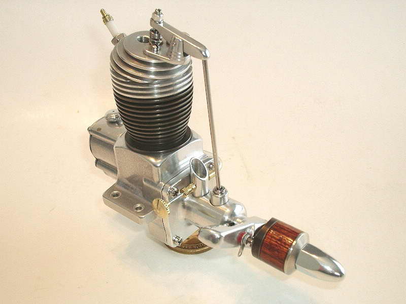
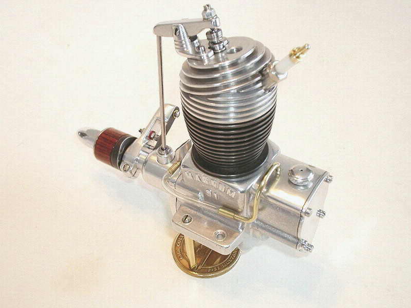
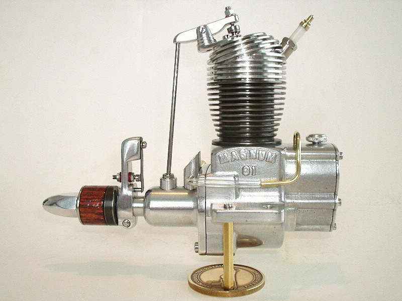
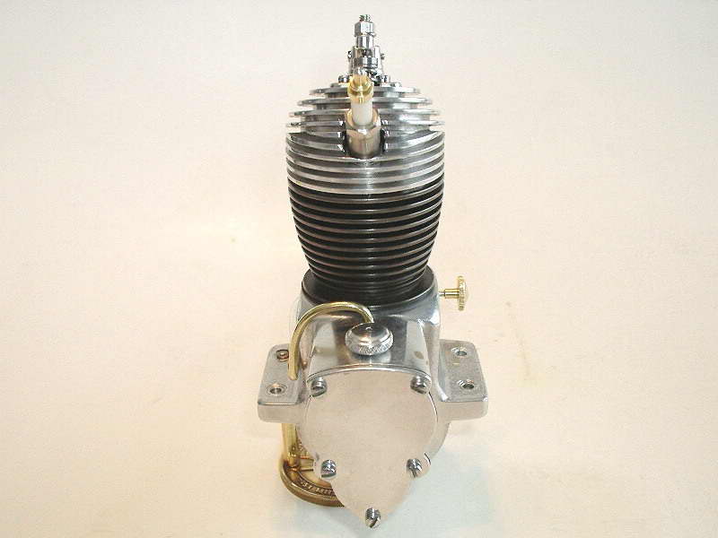
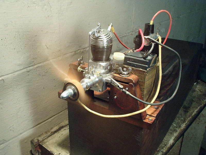
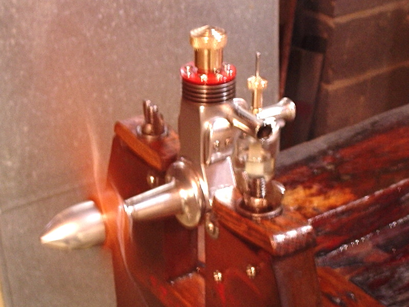
This rather unusual creation is based on a Magnum 91 crankcase casting and a Watzit that appeared in Engine Collectors' Journal #186, and in our own Watzit pages. Les completed the engine late in December, 2009 and had the following to say about it: First order of the day is a thank you to Bert Streigler who supplied enlarged pictures of the timer for the 1938 M&M, along with a drawing of the engine a number of years back from the late Ted Enticknap. This aided in the set-up for the front end of the engine, with the timer forward done in the 1938 M&M motif. The bore and stroke of this new Whatzit is 1.000" x 0.875" respectively giving a displacement of .69 cuin, or about 11.3cc. The foundation for this engine is a Magnum 91 case which has been in a drawer here for 17 years. With some modification, the gear box has become the tank because despite the valve on the head, it's a two-stroke. I liked the old world appearance of the Deller spark plug, so replicated it to go in keeping with the antiquity of the Whatzit. The timing given for the old Whatzit in ECJ is as follows: facing the engine from the front and flipping the prop to the left, the FRV begins to open at 90° BTDC and is fully closed again at 45° ATDC. The exhaust valve begins to open 90° ATDC and is fully closed again precisely at BDC. In my estimation, this timing, along with the spring loaded valve in the piston were the two main aspects which prevented the original ECJ Watzit from running. The new timing figures I have come up with are as follows, the FRV begins to open 130° BTDC and is fully closed again at 30° ATDC. The exhaust valve begins to open at 120° ATDC and is fully closed again at 65° ABDC. The piston valve in this new Whatzit doesn't rely on a spring in the piston, but is pretty much conventional in that the inner piston slides freely in the outer piston with the top to bottom movement of .076 thou. The exhaust cam is separate and after checking it's proper position, it was loctited, then pinned it to the shaft with music wire. The hole behind the valve is the actual exhaust outlet. I tried a 14-5 Rev-Up prop for the initial trials, but decided very quickly that it wasn't enough prop after getting the fingers wrapped a couple of times, even with the spark set at TDC. Moveing to a much more user friendly Top Flite 16-6 Super M (maple), it started relatively easy, but didn't break any speed records! This work is dedicated to memory of the late Roger J. Schroeder, 1931 2009. His model airplane engine casting kits assured my smooth transition from steam into internal combustion. |
||||||||||||
|
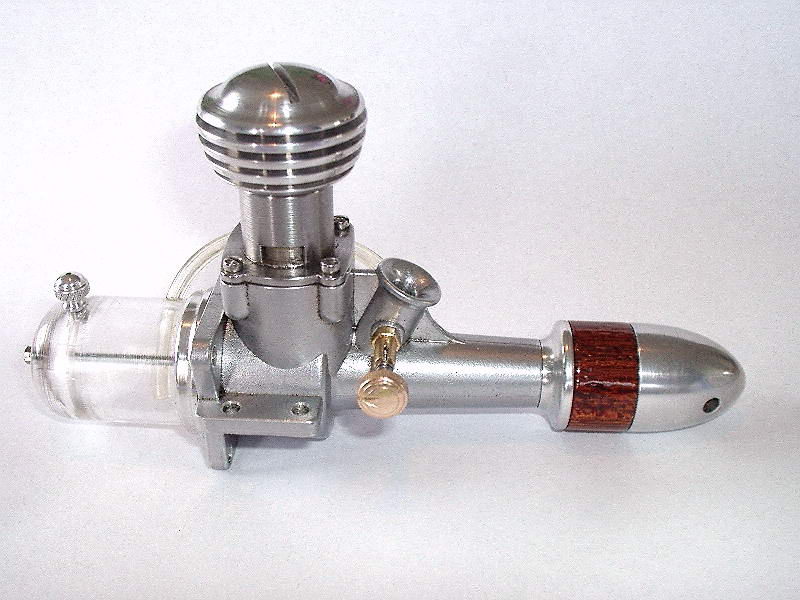
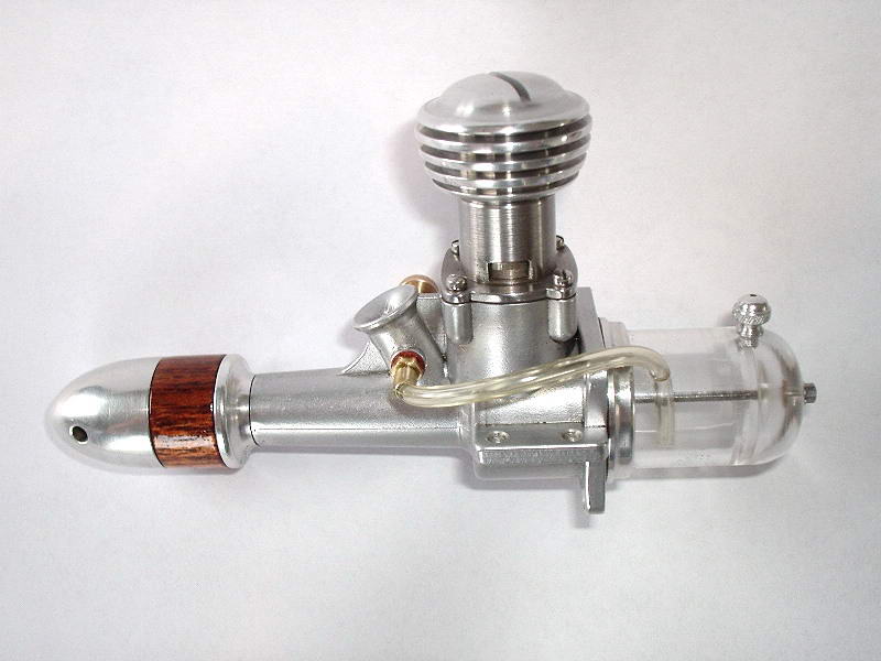
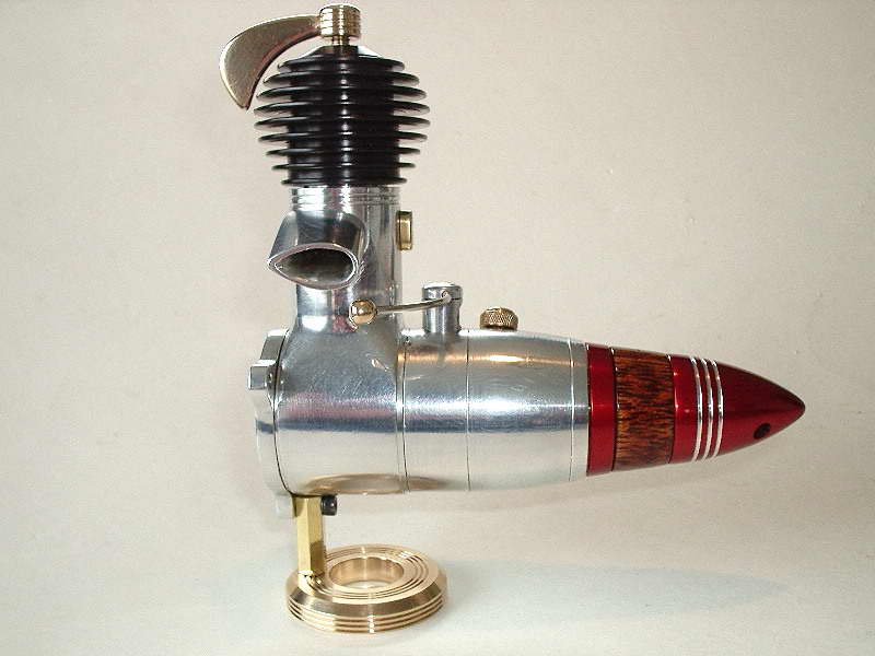
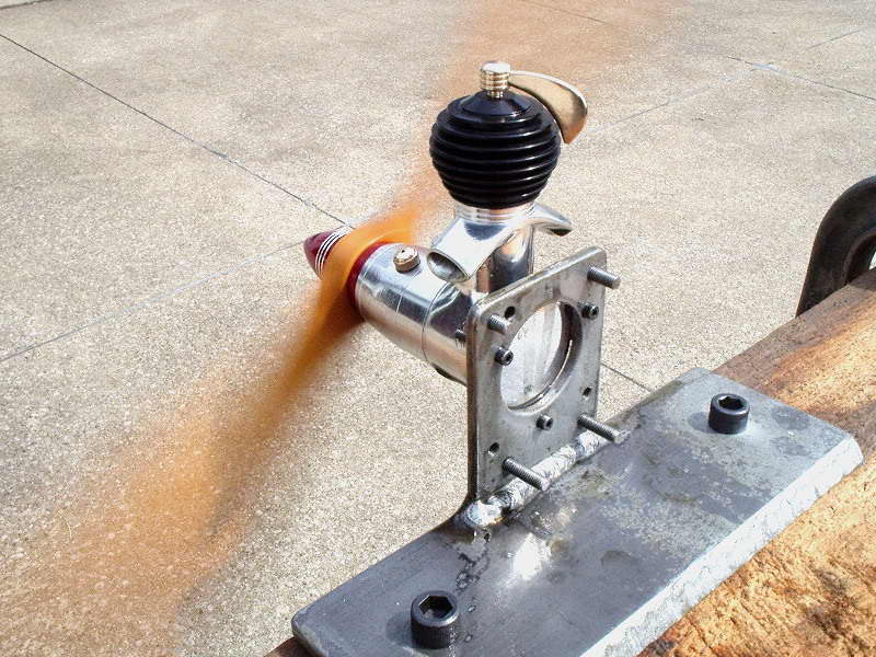
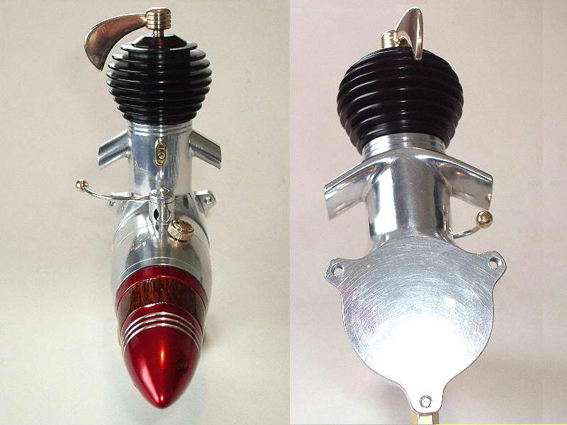
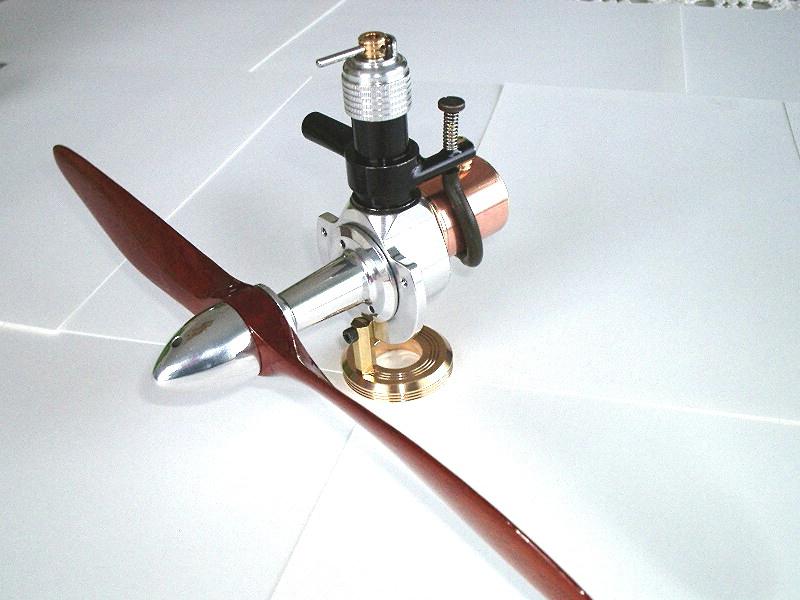
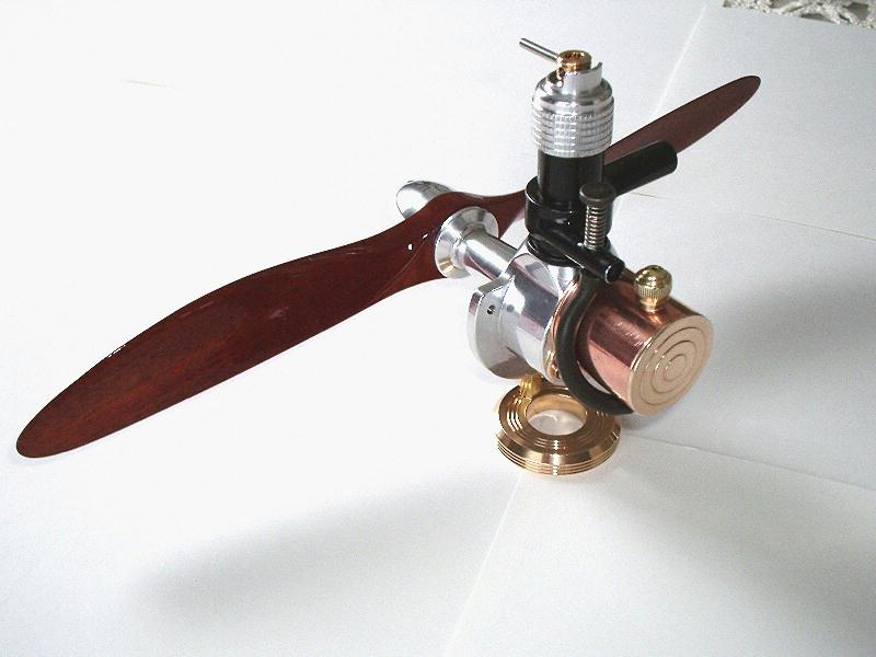
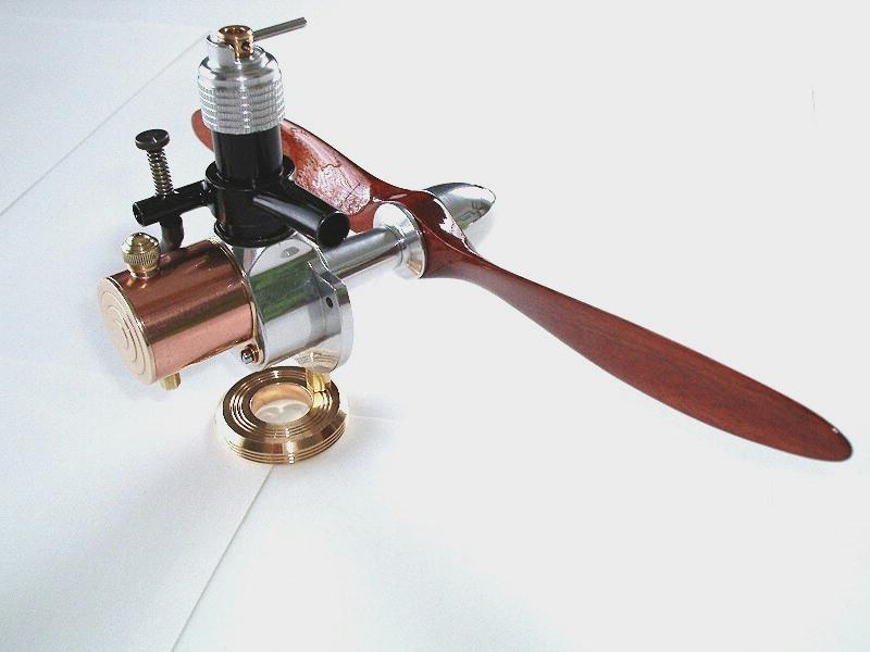
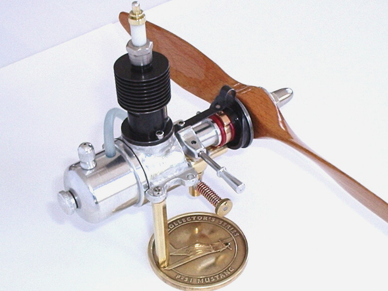
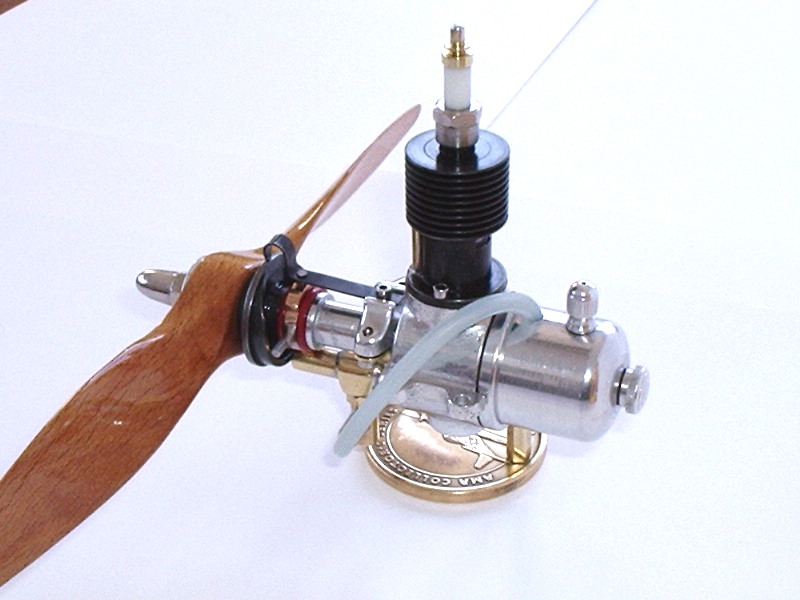
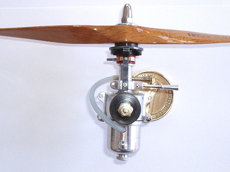
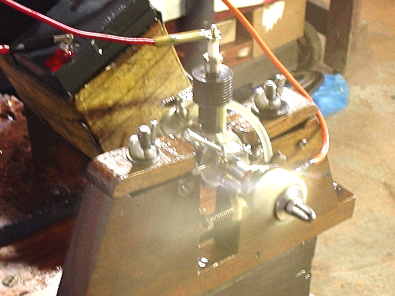
Les completed this one in July, 2009. It's a replica of the 1946 Atomatic 4 designed by Uberto Travagli. The original had a bore of 15.5mm and a stroke of 22.8mm, accounting for its tall appearance. It features a very streamlined look, assisted by the coaxial fuel tank fitted behind the prop driver, and a front rotary valve induction fed from a fixed jet fuel feed with a variable air valve, like the Pepperells from New Zealand (Les has made one of those, too). Induction metering aside, the Atomatic was conventional enough although it did feature an alloy wristpin carrier, covered with a thin cast iron piston sleeve retained by a countersunk screw in the crown. Les has deviated slightly in the engine mounts by adding three mounting ears (the original had a rather complex screw in rear plate (not a backplate as the case is blind bored from the front) that totally hid the mounting screws. One hundred points for style; somewhat fewer for practicality. Les wants to send his thanks and appreciation to Giacomo Mauro, technical advisor for Italy's SAM 2001, saying that his help, pictures and ideas were indispensable and paramount to the successful culmination of the Atomatic 3 cc project, which would have been virtually non-existent, had he not stepped in with his kind assistance. |
||||||||||||
|
Here's Les' contribution to the world's supply of ACE 0.5cc diesels.
Les credits Adrian Duncan's ACE page for sparking his enthusiasm to see this little engine through to completion. And he points out that a lot of the Motor Boys had a hand in making the reproduction possible:
Les notes that he was further inspired by the shot of Graham Podd's example on the ACE page (the one with a transparent green plastic spool up front). He liked the factory die-cast appearance of this version, so replicated on his. Always with an eye to presentation, Les machined the cylinder to have five thin cooling fins instead of the traditional four. He also added a radius on top of the comp-screw post instead of the little flat, chamfered at 45 degrees. As the prototype case casting he was working from had an over-generous draft on the main body (my fault), Les worked it from a tiny radius that starts from the mounting lug and gradually gets larger before it terminates at the cylinder flange hold down screw. And last but not least, the serial number 1110 stamped on one side of the engine which is the number of his street address in Erie, PA. The last shot shows Les' ACE spinning a massive 8x6 TopFlyte nylon airscrew. Remember this is a 0.5cc engine. That's just 0.030 cuin. Think how well your average .049 Cox Baby Bee would do if fitted with that prop. But that's one of the strengths of diesels; their ability to turn big props at a wide speed range by adjustment of compression and fuel mix. Then there's that lovely smell... |
||||||||||||
|
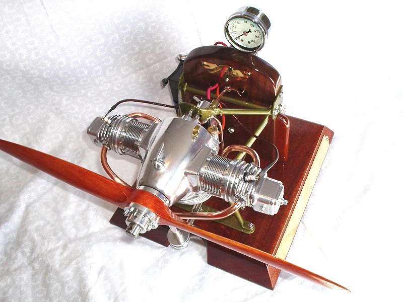
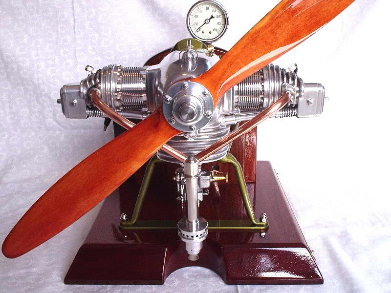
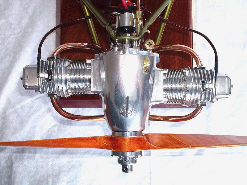
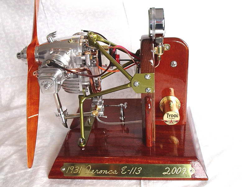
This is the Les Chenery designed Aeronca (Aeronautical Corporation of America) serialized in the Model Engineer.
In 1930, the Aeronca aircraft company in America designed an engine for their small single seat aircraft, the C-2. It was a twin cylinder opposed side valve or L-head engine of 30 hp and ran at 2,400 r.p.m. The weight was 113 lbs and the finned sump blended with the front of the fuselage. The engine was numbered the E-107.
By 1931 there was a demand for a more powerful engine to power a small two-seater aircraft. Cylinders with overhead valves were fitted to the original crankcase, increasing the horsepower to 36 h.p. with 2,500 r.p.m. and a weight of 120 lbs. The engine was re-numbered E-113 and the aircraft renamed the C-3. Aeronca engines were manufactured in England under licence by J.A.P. (J. A. Prestwich & Company Ltd.) These had a redesigned rocker box and cover to accommodate two spark plugs per cylinder with two magnetos for dual ignition placed at right angles across the rear of the engine and a power increase to 40 h.p. with 2,540 r.p.m. But the engine had reached the end of it's growth potential and was superceded by a variety of more powerful engines. The model is a 1/4 scale twin cylinder horizontally opposed aero engine
Les completed this engine in March, 2009 after nearly a year of construction. Despite the imaculate presentation, it's no show pony. In the final picture, it is seen turning a Zinger 18x6. |
||||||||||||
|
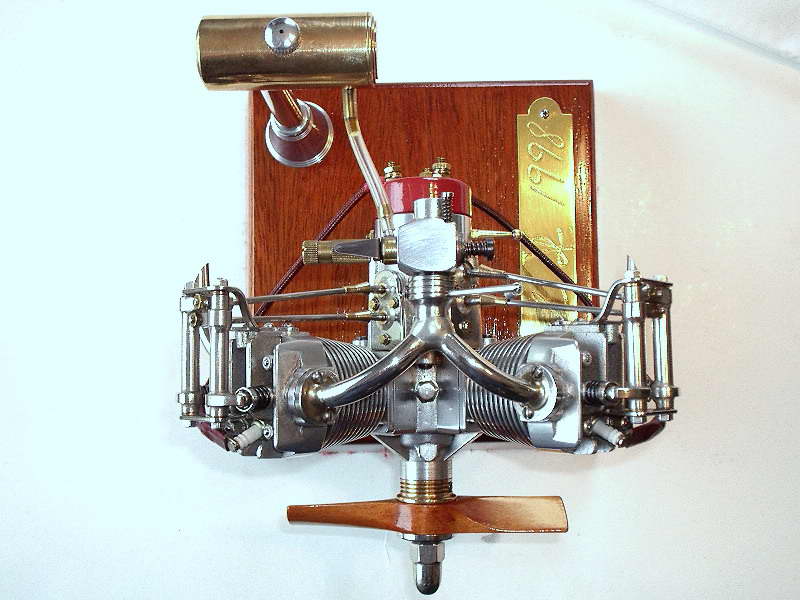
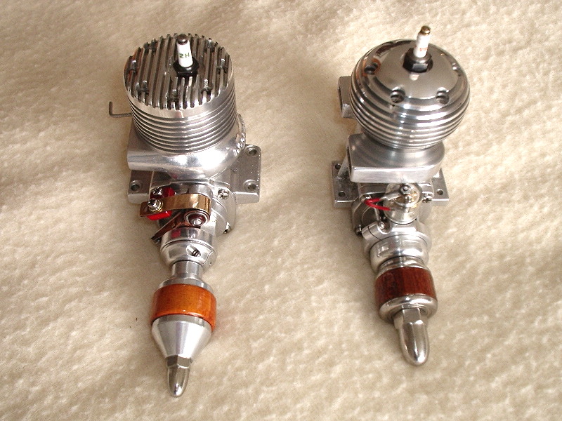
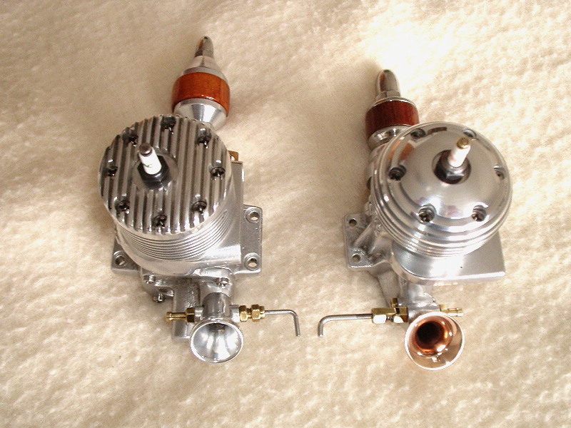
This V Twin was designed by the late Les Chenery, with plans appearing in the British magazine, Engineering in Miniature during 1983. Les (stone) completed this this example in 1998. The engine has a bore and stroke are 13/16" by 7/8" for a total displacement of 15cc. It was designed for either spark or glow ignition and Les has built his version for spark ignition with a neat distributor hanging off the gearcase. If you'd like to make one, see the Hemingway Kits website for plans, castings, and material kits. | ||||||||||||
|
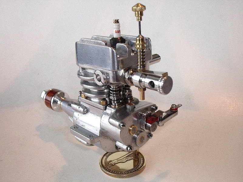
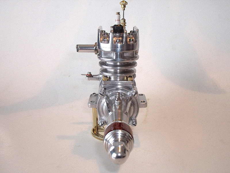
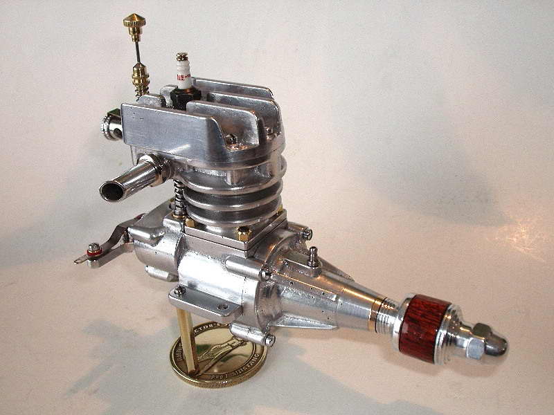
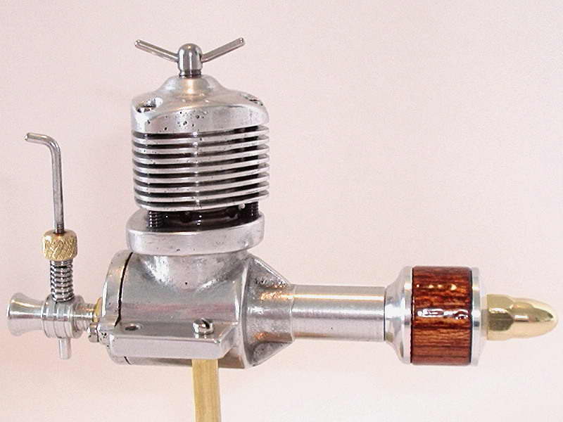
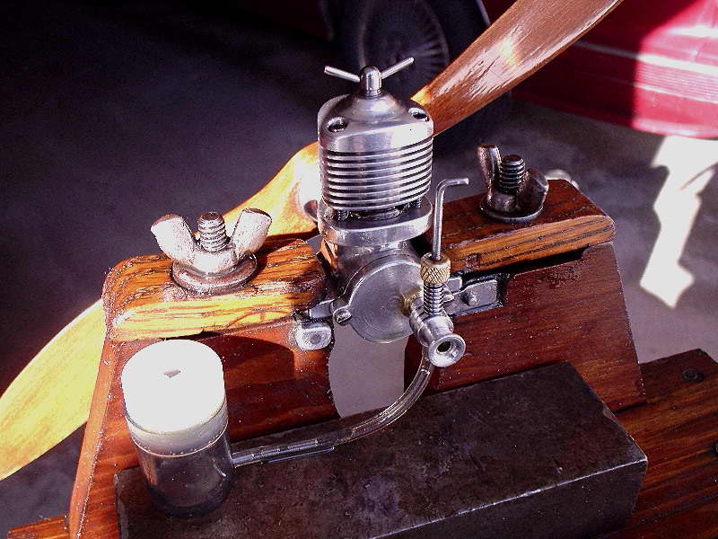
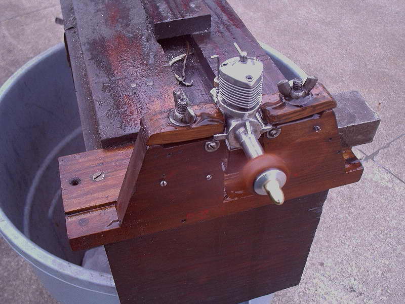
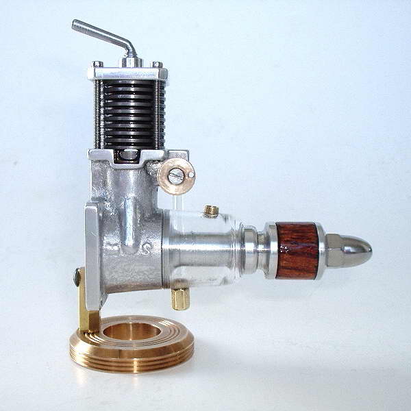
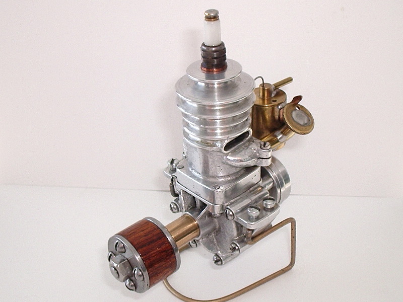
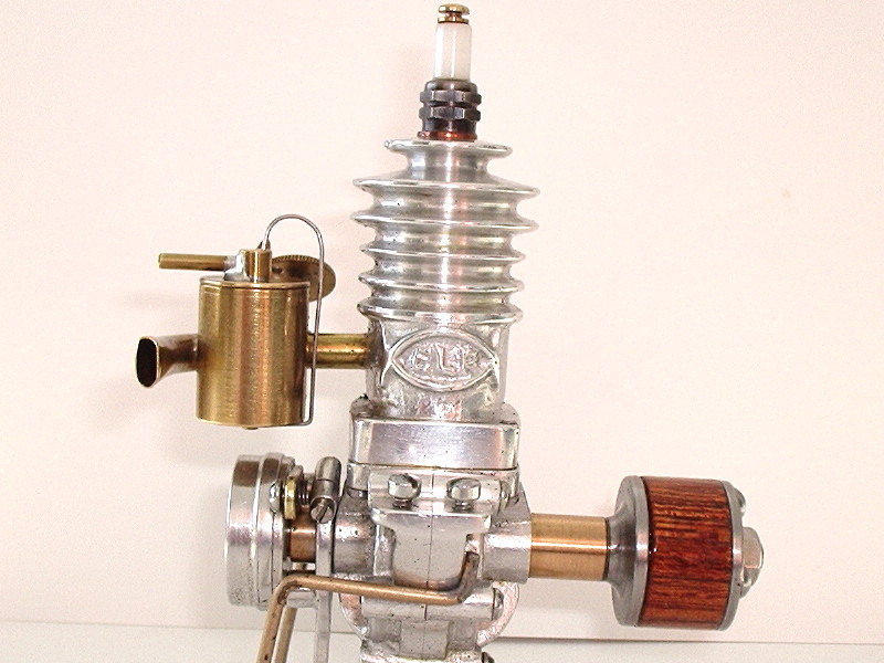
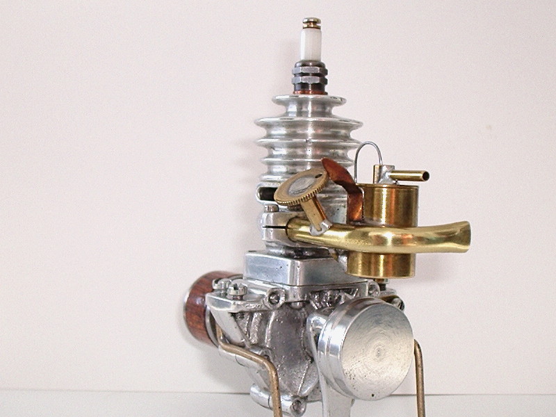
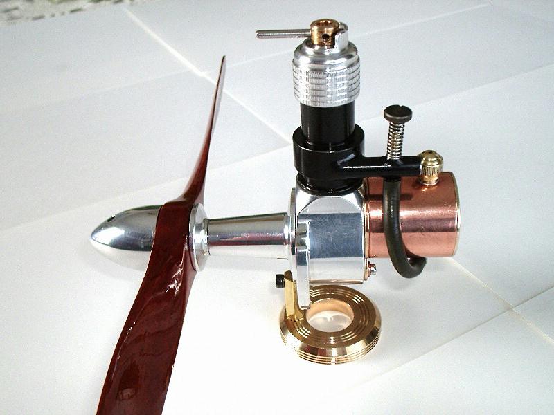
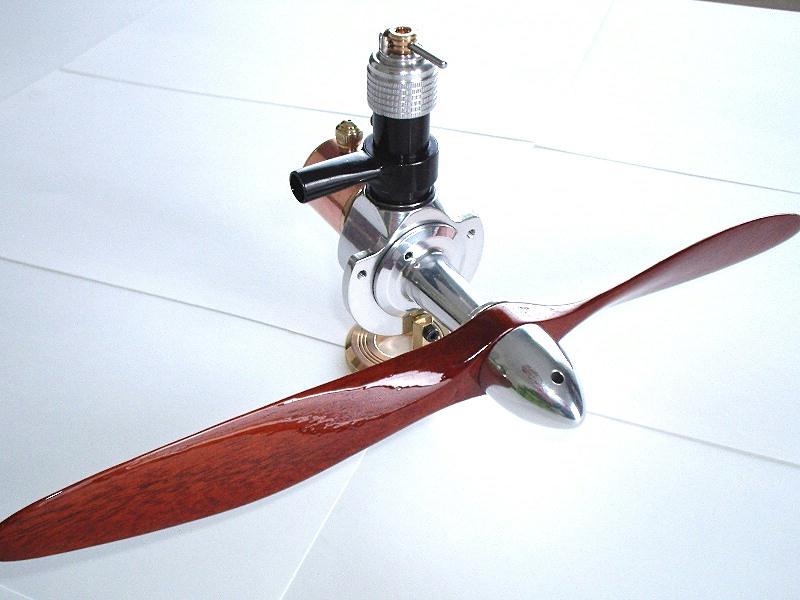
Here's Les' Chenery side-valve 5cc sparker finished in April, 2008, although the castings were first advertised way back in SIC issue #4. The engine was serialized in the English magazine, Engineering in Miniature and Les followed that series, knowing it's usually easier when someone else blazes the trail. The drawings carry a date of 1984 making this design 25 years old.
The photo of the engine in action illustrates a very practical idea: get a healthy spark from a big coil and bettery until the engine is sorted out and it's running, starting, and tuning characteristics are well understood. The cooling fins, or rather the lack of them, is one of the things that leaps out when you look at the engine. But note that the fins are tapered which makes them better at heat dissipation than simple parallel cut ones. Les says you can touch the head right after a run, and while you won't get burnt, it's not a particularely fun thing to do. Tapered cooling fins, still used in full size air cooled engines and much favoured by Westbury are seldom seen in model engines these days where lots of slit fins are more the norm. I rather like the look of the old ones. As Les says, it's a Classic. |
||||||||||||

|
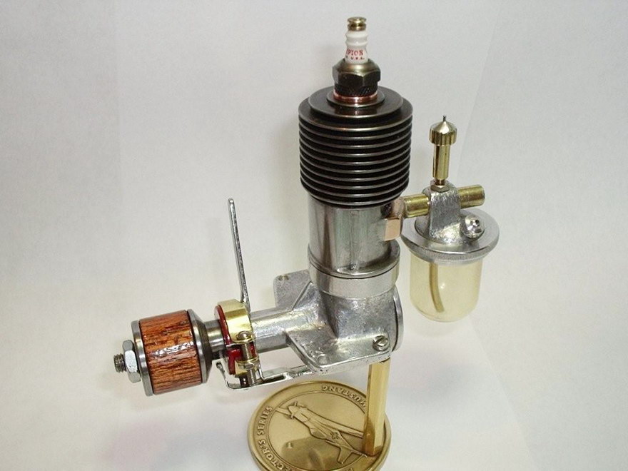
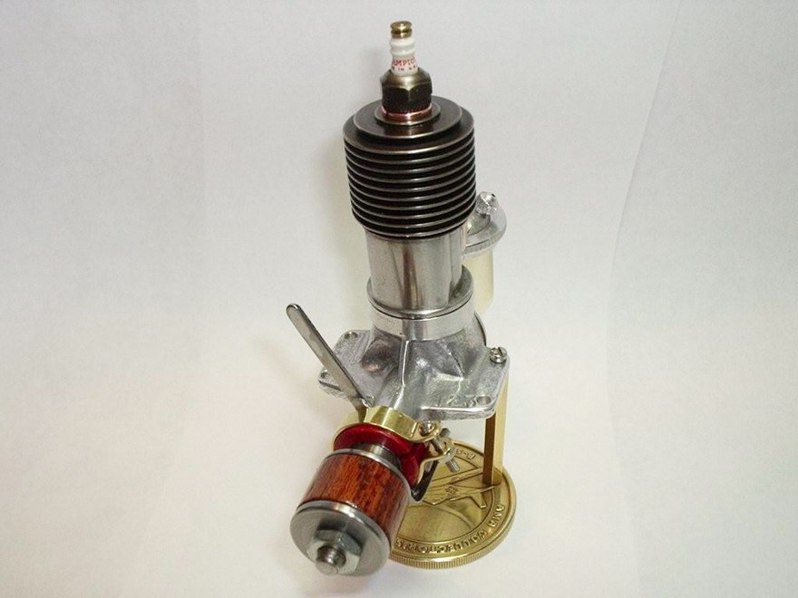
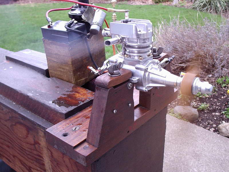
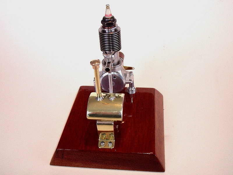
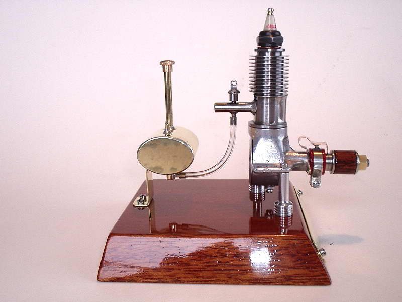
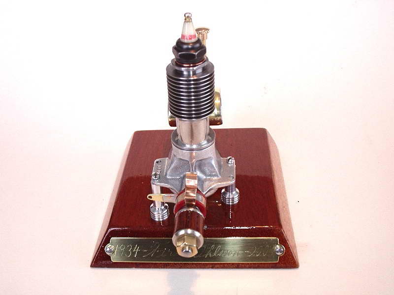
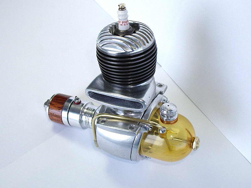
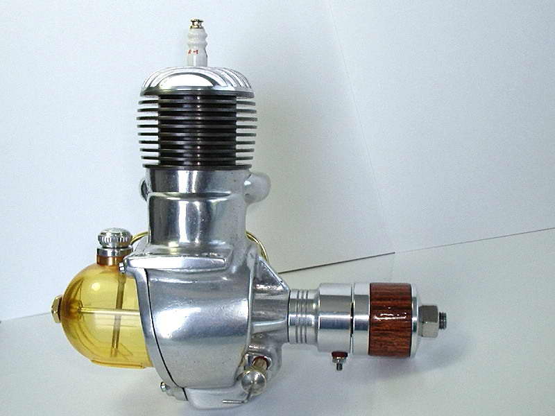
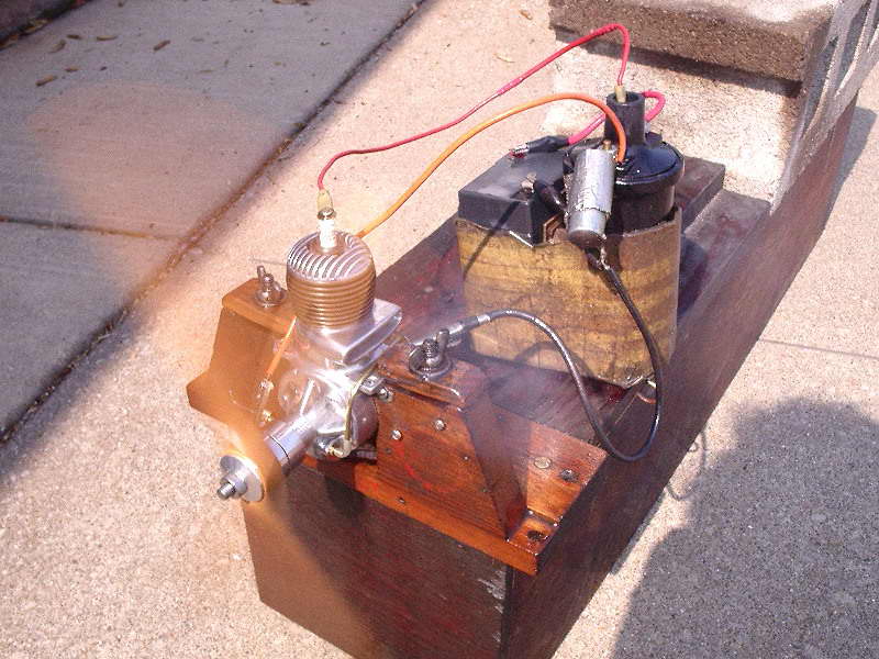
This is an Original Ohlsson Les made in January, 2008. I think he is spot on regarding the need to drop the combustion chamber roof:
Irwin Ohlsson and Harry Rice produced a long line of engines from the first days of "sparkies", right up into the early 1950's. My first engine was an Ohlsson & Rice 60 sparker. I was ten years of age at the time and purchased it at a local hardware store with newspaper route earnings, the price at that time being about $14.00 NIB. The original Ohlsson seen here wasn't one of Irwin's production engines, but instead, was one of his first prototype engines. The story of this engine and the Popular Mechanics plans that appeared for it in 1937 are detailed in Roger Schroeder's series published in SIC, issues 6 through 12. Roger still supplies plans and castings for this engine, but I've had kit #160 on the shelf since February 20, 1991, that's 17 years ago. So I deemed this 1934 original Ohlsson kit an appropriate build and fitting tribute that marked the introduction to my O&R collection. The moving point on this original Ohlsson was made of the same material that was supplied in Art DeKalbs Elf Goose Egg 4 casting kit, which he had listed as Phosphor Copper sheet, 0.015 thick. There was ample material left over from the kit that would allow another moving point to be made for the original Ohlsson, which can take a bend way past 90 degrees without breaking and still retain it's bouncy, resilient spring tension, that is required for this particular moving point. Regarding the spark plug, ECJ states on page 4, volume 4, number 5, April, May, June 1966 and continued on page 16, volume 5, number 2, November, December 1966, that the first 3/8-24 production AC (Albert Champion) and Champion spark plugs started production in 1936 and 1938 respectively. This was late for the 1934 Ohlsson, so in order to bring the authenticity in more accurately, I replicated the spark plug that is shown in SIC #7, page 11, which is a photo of the actual first original Ohlsson, built by Irwin and a close associate. From my own judgment and experience, the combustion chamber space was excessive in the first Ohlsson, but supposedly, this was the order of the day at the time this engine was built. I wanted to improve performance and also achieve a good reliable 2 cycle run, while retaining the originality, so the first item to take care of was to keep the 1934 theme of things on the outside, but cut down on compression space inside. The original spark plug I made for this engine had the Corian insulator coming all the way down to the bottom of the 3/8-24 thread, this in effect closed out the underside of the spark plug that was left overly open in the early V-type spark plugs which added to the head volume, lowering compression. The plans show a screw-on head but I did a blind bore, decreasing the distance between the roof and piston baffle by 0.060" at TDC and making one less place for compression leakage. The one other location to use up compression space was in keeping metal from the top piston baffle, down to the piston flat, on a gradual concave radius and to terminate with the bottom exhaust ports at BDC. It all must have worked because the little 0.12 cuin engine ran well on a gigantic 9x4 wooden Flo-Torque prop, giving 5600 to 5800 RPM |
||||||||||||
|
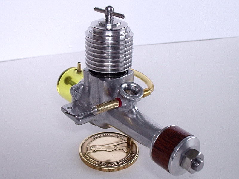
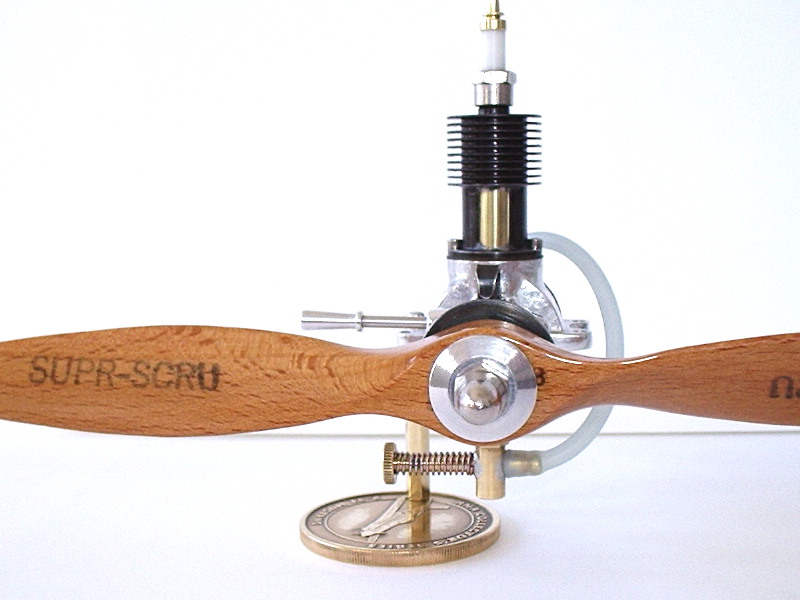
This little beauty, Les' October 2007 creation, is a Custom Humbug and you'll have to read the reference under the link to find out why. The intent of the design was an engine that could be made without thread-cutting, or any specialized tools like slitting saws and milling—all plain turning, drilling, and tapping. Les found that suction was a problem which he addressed by inserting a sleeve in the venturi that reduced the internal diameter from 0.140" to 0.125". This fixed the problem and the change has been made in the plans. The figures on it are Bore 0.5", Stroke 0.46", for a capacity of 0.09 cuin (1.481cc). As seen in Les action shot, it is turning a massive 12x4 wood prop at 5,000 rpm. Les says that as he's getting on a bit, big props slow the engines down to a point where he is sure of his fingers getting out of the way first! The extra flywheel mass helps on first starts too.
Les has built this one as a straight rear rotary valve diesel, but the plans show how it can made convertible for either diesel or glow ignition, and with RRV or reed valve induction. In the "bar-stock" configuration—simply known as the "Humbug"—it is rather pedestrian in appearance, but if Roger Schroeder's castings are used, the appearance is totally transformed. Plans are scheduled for a future edition of Model Engine Builder magazine and it's great to have Les' help validating the design so readers will ultimately benefit from his experience. | ||||||||||||
|
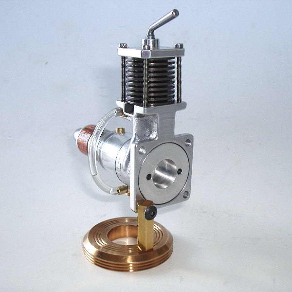
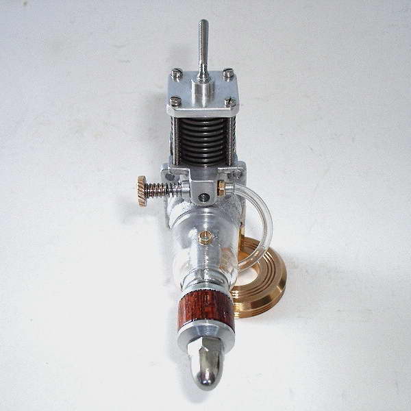
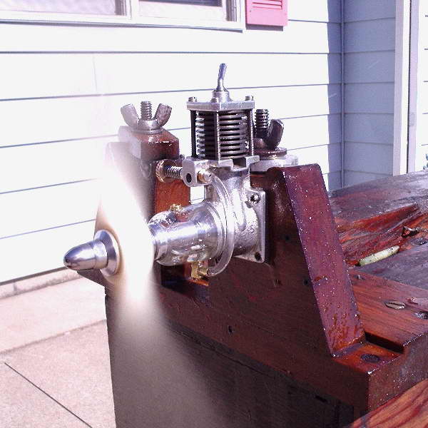
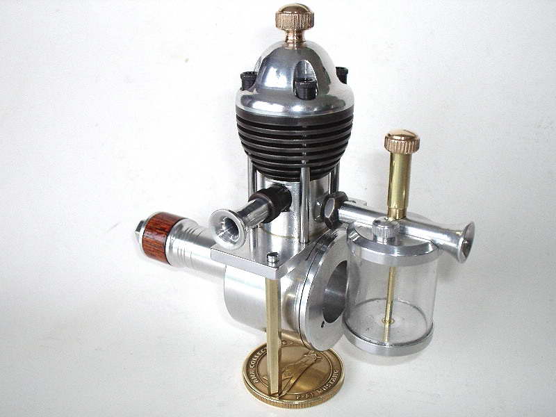
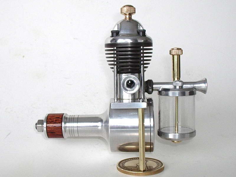
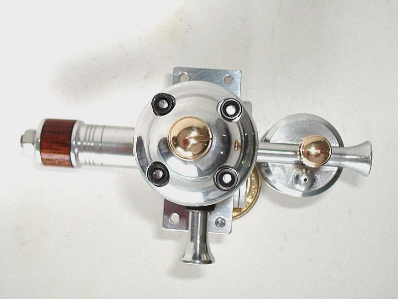
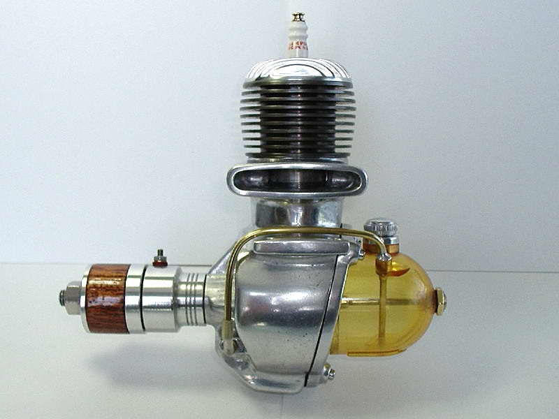
Like the rest of the Motor Boys, Les likes subjects that are just a little out of the ordinary. The MS 1.24 qualifies by having the forward facing side-port intake, and the co-axial fuel tank. "MS" stands for the Model Shop (of Newcastle, England, see Model Engine News, March 2004 for more information about the company). The engine itself was first seen here in 2004, and later, was the subject of a slightly more in-depth review. An example of the original engine reputedly sold at a Guilding's Auction (UK) for 450 pounds! Les' example was produced from his own casting, poured using a pattern made by Graham Podd. Les says:
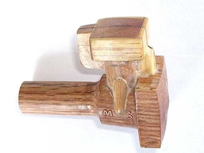
I received a package and letter from Graham Podd in November of 2005 containing his pattern of the MS 1.24 saying it's yours to keep if you want it, I have my one example of the engine, so no longer need the pattern, needless to say, I gratefully accepted. The pattern laid around for a couple of years and finally became the center of my current project. If you look at the pattern closely, you can see how he bent and attached the fine copper wire to form the letters "M S". The photos show my finished engine and one of it running with a Top Flite white nylon 9x6 prop. I tried the tach, but numbers were jumping from 5000 to 10,000, and then back again. It wouldn't stay in any set range yet the engine stayed at one set speed—maybe low batteries, or they sat on the shelf too long. |
||||||||||||

|
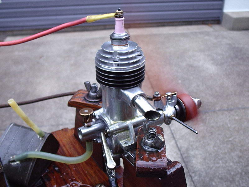
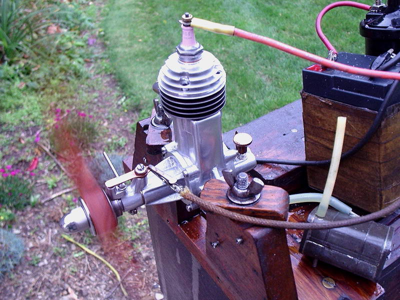
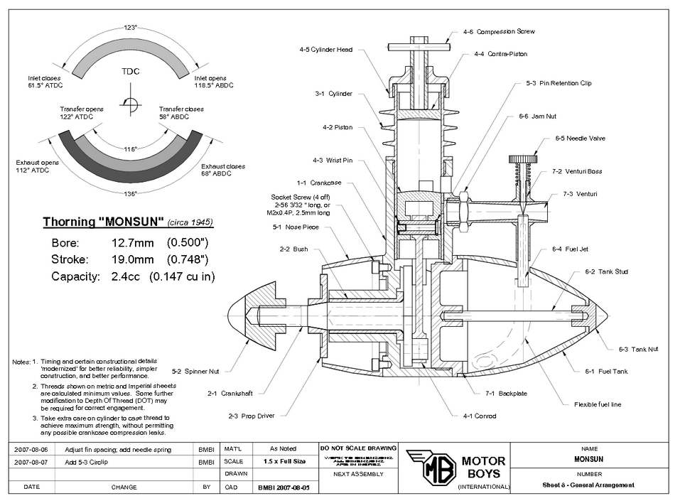
Here's Les' rendition of the Thorning Monsun, a vintage 2,4cc Danish long-stroke diesel from 1945, or there-abouts. The engine is remarkably advanced in having Schnurle-like transfer porting—used here then forgotten in model engines for the better part of the next twenty years! Les moved the exhaust from the rear to the front as he felt that the cluster of ports at the back were all just too close together for comfort and acceptable timing. There is even historic precedence for this. Have a look at the Viking, another long-stroke diesel from Denmark.
The other thing here that looks rather like a bathroom fitting is the nose piece. Again this shows Les' lateral thinking on how to make a complex part simpler. If it does not look simple, have a look at part 5-1 on the GA of the Monsun that shows the part formed and fitted as designed. Les reports that the engine was initially a bear to start, but is loosening up nicely and really moves a lot of air turning a Top-Flight 13x5-3/4 wood. Try that with your average .15! |
||||||||||||
|
This bar-stock engine was designed for first time builders by Andy Lofquist. Andy's operation is called "Model Lathe Accessories", hence the name MLA Diesel. The MLA kit for it included three double size drawings along with 4 Allen head nuts, one taper pin, 3 Viton 'O' rings and one small container of diamond lapping paste. It has a bore of 0.500" and a stroke of 1.000". Les has this to say about it:
You may notice my head has an unusual shape as compared to Vincent's perfect sphere shaped head. In Andy's instruction booklet, he presented a table of coordinates, but I misinterpreted diameter for radius and dropped into the head too abruptly, so had to re-group if I was going to save it. There was enough previous machining on the head that I didn't want to go through this again. If you catch a side view shot it, the resemblance is that of a pith helmet—needless to say, the day was saved. It starts very easily, just one choke and it's off and running; 5,200 RPM on a 12x6 prop. Pith helmet yes, but more like an acorn to me (not that we actually have such trees Downunder, so what would I know). For an example of how it might have turned out, have a look at the one made by Dr Battiwallah himself, Oz Motor Boy Vincent Chai. A picture of Vincent's example graced the front cover of SIC #78 and provided Les with the spark of inspiration needed to finish his. |
||||||||||||
|
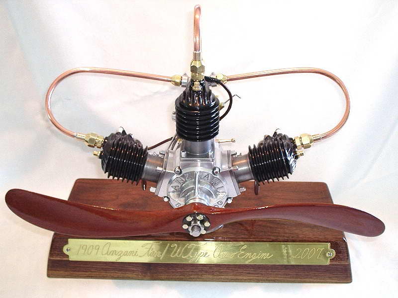
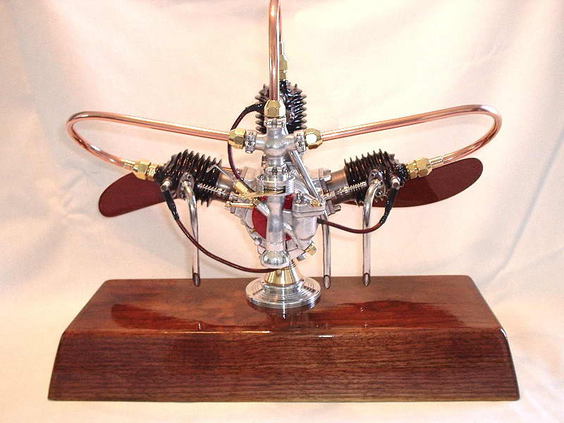
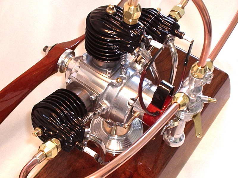
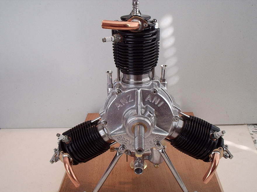
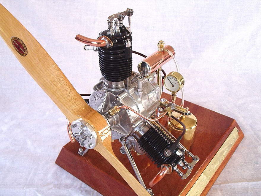
This project was completed by Les in May, 2007 after ten months of effort.
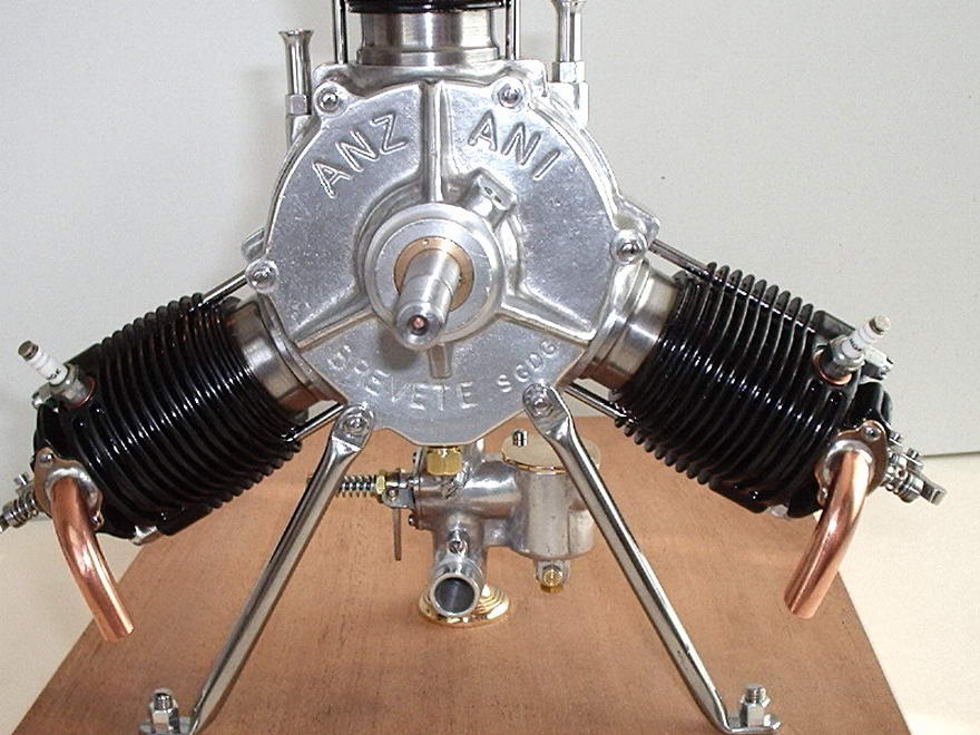
The subject is a quarter scale 1909 Anzani Fan Aero Engine, originally designed by Alfred Eichinger of Sieghartskirchen, Austria, which appeared in the final three issued of SIC.
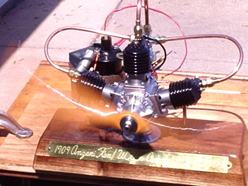
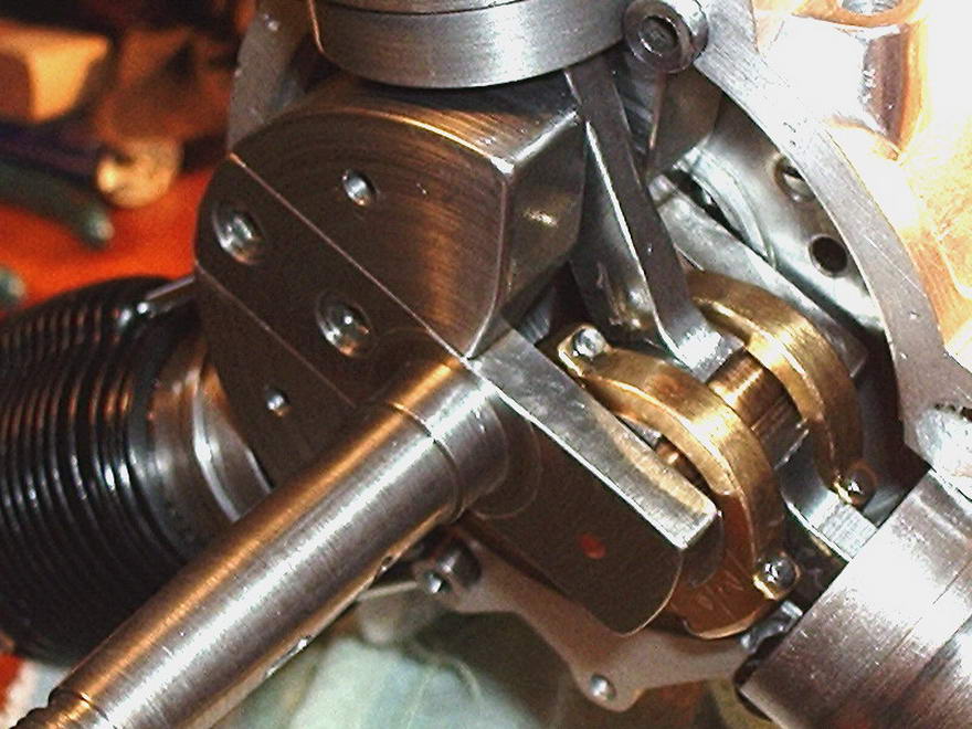
Les says that the most significant change he made on this particular engine was to the ignition system (Unterbrecher). The magneto is a dummy concealing a distributor running at half engine speed off the center camshaft for number one cylinder. The engine base is comprised of two one inch thick laminae of Black Walnut hardwood, which gives the base it's final thickness of two inches. Like all Les' engines, this is a "runner", not just a "looker". which raises the question of how does it sound? When asked this burning question, Les provided the following description:
"...Da Da—Dum, Da Da—Dum, Da Da—Dum..."
Real old fashioned, just the way it should sound! The reasoning behind this is the firing intervals. The firing order is 1-3-2. The rotation is counter-clockwise viewed from the front of engine with cylinder #1 at top center, #3 on the right, and #2 on your left. When cylinder #1 fires, the crank has to go around 288 degrees to put #3 at TDC for firing, after 3 fires it only has to rotate 144 degrees to put #2 at TDC for firing, so from #2 it goes 288 degrees around to #1 again. The cam I made runs at half engine speed and has 3 lobes. The angle between the lobes is effectively cut in half. Looking at the top of the cam is #1 lobe, then drop down towards the bottom of the cam, 144 degrees either side of #1 lobe and add two more lobes with only 72 degrees between them on the bottom of the cam. So the two that fire closely together are "Da Da", and the more distant one is "Dum". Incidentally, there are no wasted sparks on this set-up. |
||||||||||||
|
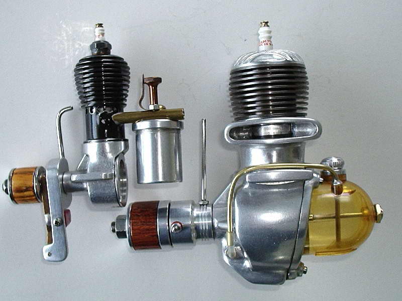
Here we have Les' rendition of the Majesco Mite, a rather rare little British diesel from our Motor Boys CAD plans, prepared from sketches kindly provided by Motor Boy Ken Croft. The engine it's posed against in the second photo is a Topsy, another Brit design of rather distinctive and similar appearance that was designed by Mr G Hugh and serialized over four issues of the Aeromodeller, starting in February, 1969. Regarding the Mite, Les says:
I got 5 tank-fulls through the Mite today (2006-09-09). The photos show it together with Topsy, two real powerhouses so to speak. This is about as close to Gasparin building as I ever want to get! The diameter of Topsy's piston is 5/16" followed with the Mite piston being 3/8". The Mite swung a Top-Flite 8 x 6 white nylon prop at a very respectable speed. The side view shot shows the bypass cover on the Mite which is .020 thick stainless steel. Les used no castings for his Mite. The basic case is hogged from the solid. The venturi was pressed in and a fillet of JB Weld used for added security. Les swears by this stuff. It dries grey, so he's touched it up with silver paint to resemble a first-class TIG welding job. If you look closely, you'll notice the fins on the engine are "thread form". Evidence shows that originals exist with this rather extreme example of tapered fins and more conventional straight fins. I think the tapered ones add to the period charm of the engine. | ||||||||||||
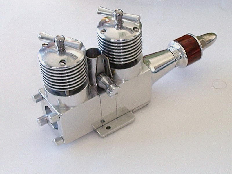
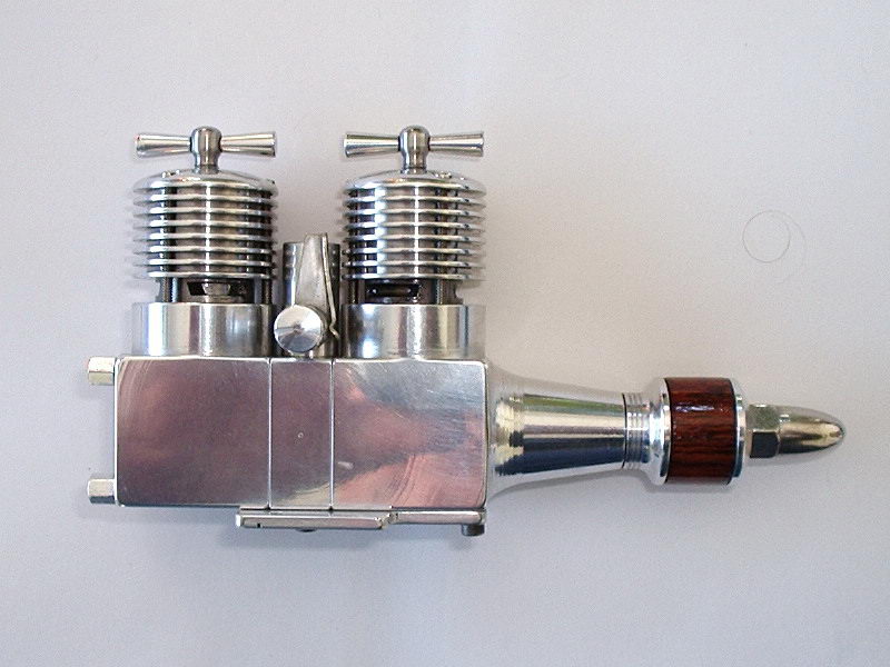
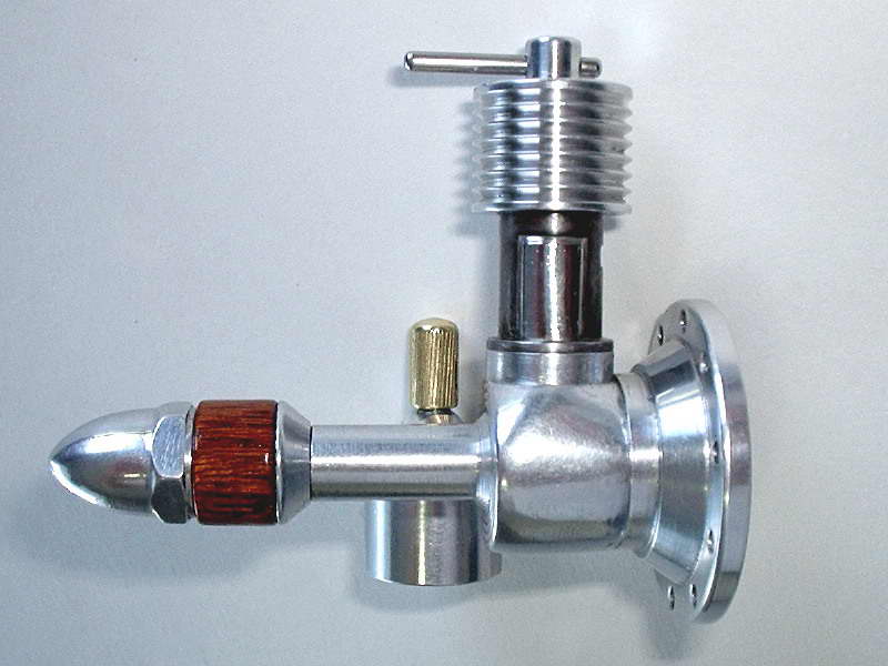
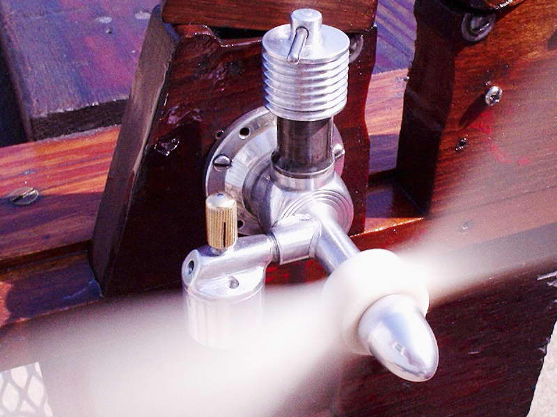
|
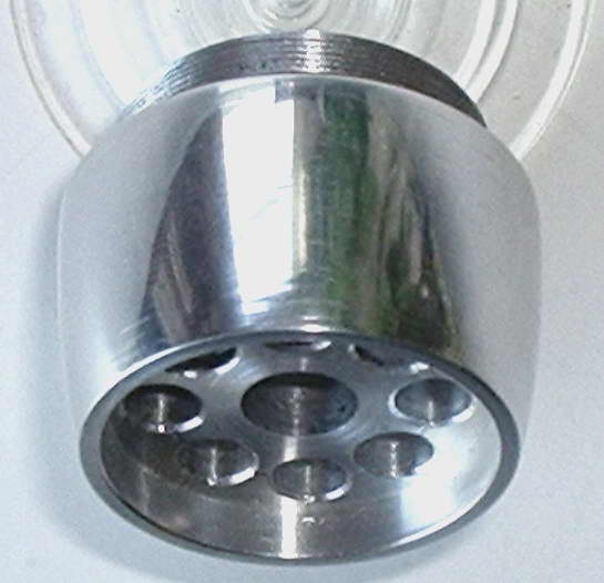
This is Les' rendition of a twin that appeared in SIC #15 of June/July, 1990. Les completed this one in February 2004. It was designed by Australian Stan Hinds, hence the name "Hinds Twin". As twins go, it's a relatively simple and very practical engine to build, being based on commercial cylinder liner/piston assemblies—PAW 1,49cc units in this case (notice the characteristic PAW "dovetail cut" of the exhaust openings).
While using finished cylinder assemblies helps, no twin is all that easy to build when you get to the crankshaft(s). The Hinds Twin is alternate firing, so the central "spool" has two inlet ports 180° apart with a deflector piece that is angled between them, sealing them from each other and providing the alternating induction from the single venturi. This results in two bangs per rev and Les says it does not just howl, it positively SHRIEKS! | ||||||||||||
|
First, here's what Les had to say when he sent out the pictures:
Hi all, finally the big brother to the Lindberg Hornet A which was received as a casting kit from Roger Schroeder February 15, 1984—22 years ago and was my introduction from steam into internal combustion, a sudden change that really presents more of a challenge. The castings and construction series for the Lindberg Hornet C have been on hand for a number of years as received from Denny Hitson. All this aside and on to the main ingredients of the Hornet C. The case, cylinder and head are all threaded to screw into one-another. This eliminates the 4 hold down bolts and to a degree resembles an O&R aluminum head staked on to a black cylinder. The ignition set up shown on the previous drawings I sent was inadequate at best. I had an O&R moving point, so decided to turn down a housing and pivot post for it. This worked out all right. The amber fuel tank is a new repro Super Cyclone tank made to work with some modification, because there were 2 tank options given on the drawings, that is out of metal or Lucite ! That's a term in reference to plastics I haven't heard for a long time. Finally, the prop you see swinging in one of the attached pics is a 14x5 REV-UP wood. I still get that thrill firing up an engine that you've spent a considerable amount of hours in it's building process. Now read between the lines. Les' Hornet B exhibits all the skill and hallmarks of his Hornet C. They sure don't look like they were build 22 years apart. Next, look at all Les has produced in a mere 22 years! This page is by no means exhaustive; it omits all his multy-cylinder engines, including the pair of Furgerson boxers, an Elf Goose-Egg, a deHavilland Gypsy 1 and a Hodgson 9 cylinder radial!! | ||||||||||||
|
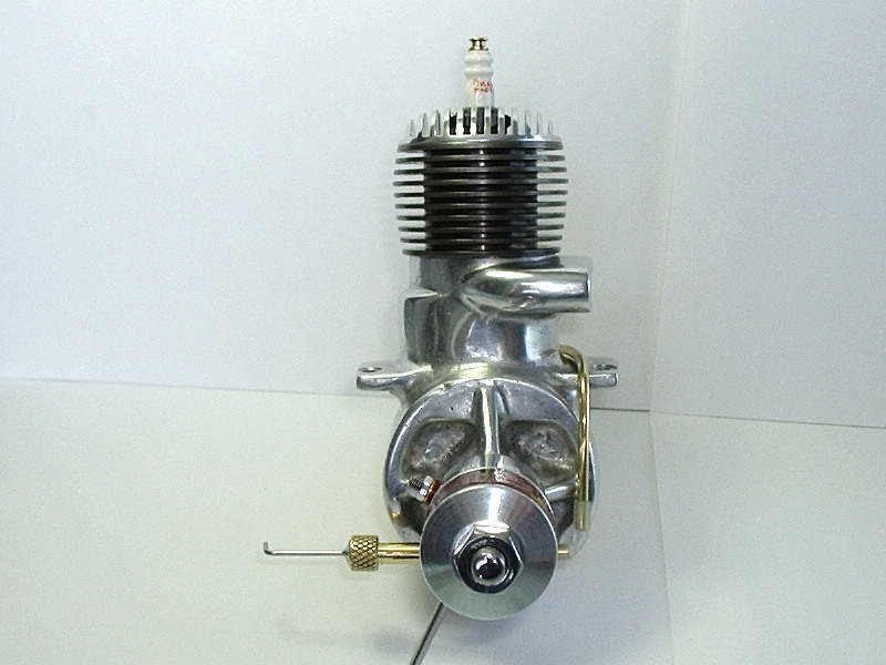
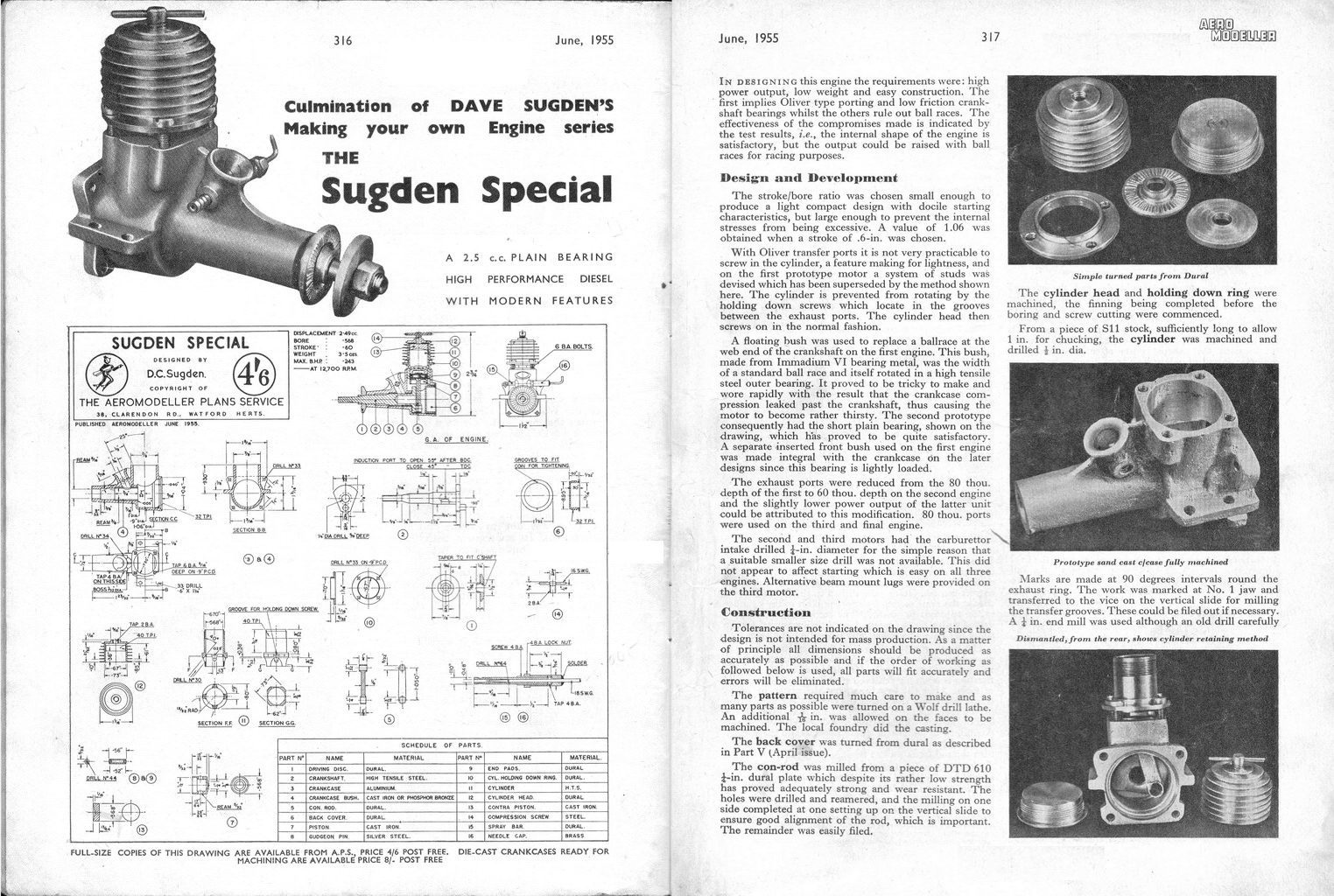
Les' version of the Sugden Special has some touches of his own, some obvious, some subtle. The backplate mounted tank is the most obvious. Not so immediately obvious is the changes Les made to the cylinder retention. A close look at the area around the exhaust ports shows that the bosses for the liner hold-down screws have not been used. Les prefers a screw-in liner, so that is what he made. As the transfer passages are external on the Sugden, this makes the lower portion resemble a big thread cutting tap, and one starts to think of possible trouble with cross-threading. But Les reports this is not a problem and in fact, there have been commercial engines that were made exactly like this and survived contact with their owners.
Impossible to see from the outside is the change Les made to the crankshaft. As shown on the plans, the Sugden featured a dual diameter journal, running partially bronze bushed, and partially unbushed in the case material. Les' shaft is a constant diameter, running unbushed in the case. Some simple re-design provided the same inlet timing as the "standard" Sugden. This sort of modification will make purists shudder, and pragmatists nod in appreciation. Obviously the engine itself does not care, as it runs just fine. Incidentally, the case is a sand casting from Canadian Motor Boy, Andrew Coholic. |
||||||||||||
|
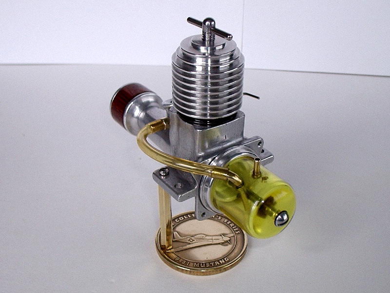
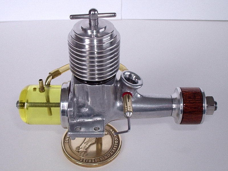
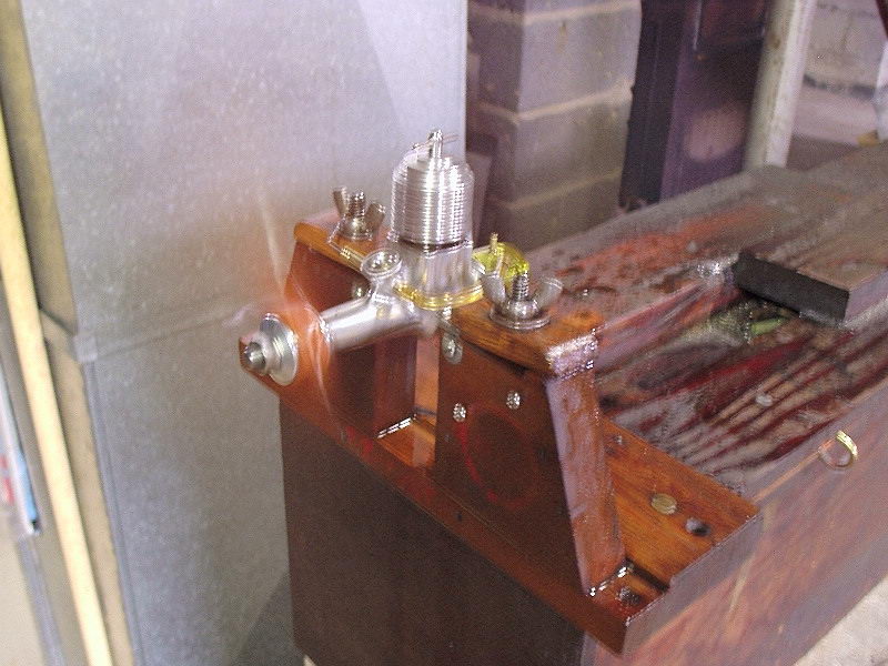
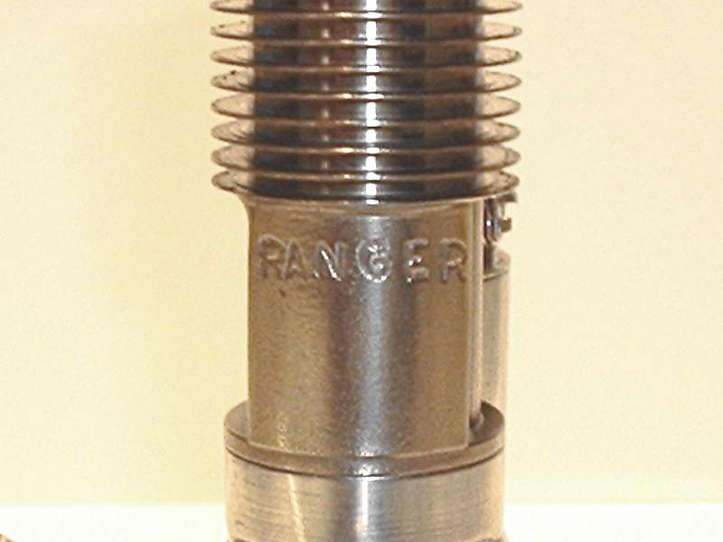
The Ranger B is a 1/2 size Brown Jr. look-a-like that you can buy for about $US300. That price was just a bit high for me, so I made the split pattern you see attached with the engine.
The only cost of this engine is time and material, but that's what the hobby is all about, isn't it?
This is the only split pattern I ever made because sometimes the mating pins are effected by the moisture in the sand and you don't need any pattern that is reluctant to come apart at this stage for fear of destroying the mould, therefore my preference is the solid pattern with plenty of draft. |
||||||||||||

|
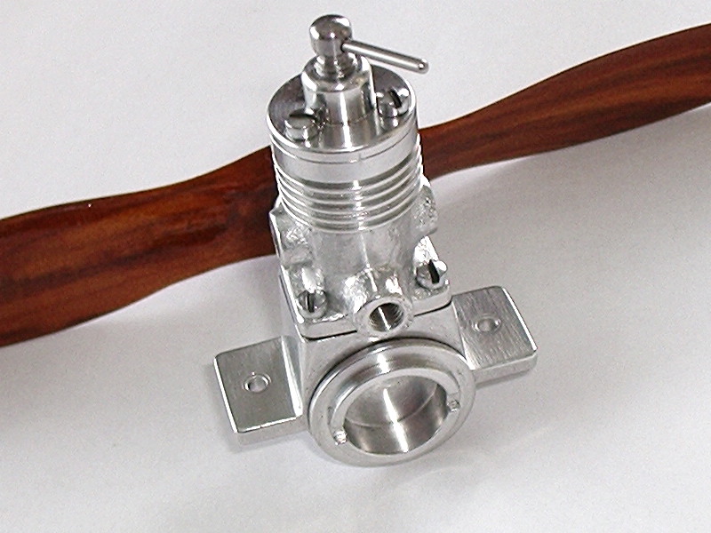
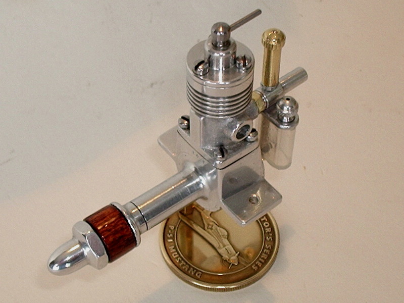
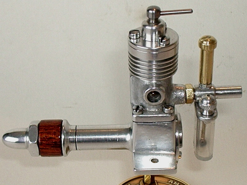
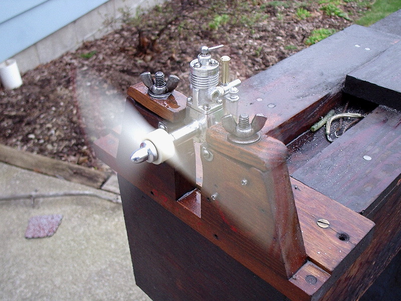
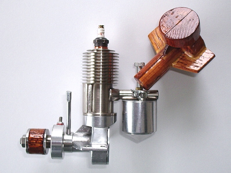
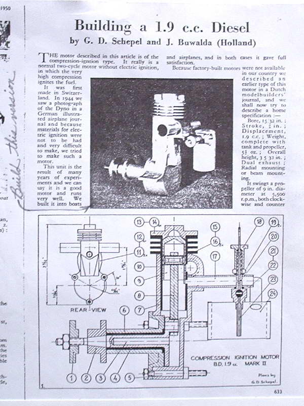
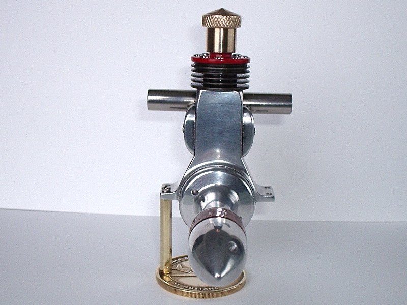
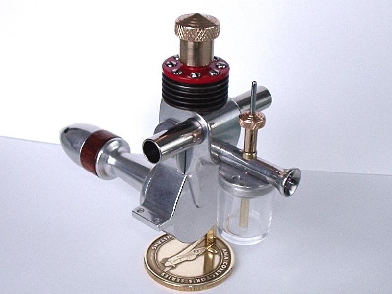
Greetings everyone, attached is my most recent effort, taken from October 26, 1950 Model Engineer designed by G.D. Schepel and J. Buwalda of Holland. The 1.9 CC given is misleading and is actually 1.777cc figured on the basis of a B&S equalling .470 x .625. It swings a propeller of 9" diameter at 5,500 RPM according to the article, but doesn't mention the pitch. My engine attached is swinging a late 40's/ early 50's vintage 12 x 4 Flo Torque wooden prop. I didn't tach the engine because it is still much too tight, but it sure pushed a lot of air around and sang a lovely song. I guess after one's long hours of building the engine, this comes as your just reward, even more so if you were to mount it in a model aircraft. The plans originally came from Denny Hitson about 5 years ago. I toyed with the idea of building it back then, because to me, it seemed like a very desirable engine, but other projects got in the way and it was soon forgotten. Then more recently, Graham Podd sent me the same plan and then it really put the hook in me and helped rekindle the spark I previously had for it. Several different options were given in the plan for building this engine. Three ways for the crankcase, I chose out of a solid block of 6061-T-6 aluminum. There was also two tank options given (vertical or horizontal). My choice here was vertical. There also was two choices on compression: fixed or variable. My choice here was variable. The final item that had two choices, was the front end bearing. Either bolted in and held with 3 bolts or screwed in place. My choice was the latter with a left hand thread. The attached general arrangement of the engine gives you some idea of what it's all about. |
||||||||||||
|
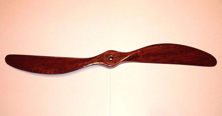
This engine should be familiar to all regular MEN readers, although the eagle-eyed will spot some differences from the "classic" version (as described in John Brown's excellent book, Dan Calkin And His Elfs). Here's how Les describes his rendition: Quite some time ago, several of the Boys built the model 1 Elf, or as it is more commonly referred to the Elf Corn Cob. At that time, I had a kit of castings for subject engine sitting on the shelf for at least 10 years, but when I saw the Boys doing their thing on this engine, far be it for me to pass it by, so off the shelf they came. I had a near miss on losing the front half of the case, so had to pull back and regroup, hence the long bronze bearing loctited in the front. How do they say it,(if you get handed a lemon, simply make lemonade). This led me to a two piece crankshaft, the front one with the longer crankpin, and the rear one with the hole to accept the long crankpin which in turn drives the distributor. The tank is also different in that it is just that, a tank without the float. All I do is fill it up and run it dry. The piston isn't original as with rings, it is lapped to the cylinder. The one outstanding flaw at the base of the needle valve is the solder not quite joining all the way around the base. I had been tempted to re-solder the joint but sometimes in a situation like this you can open up the preverbial bag of snakes and put yourself in a worse position than you are presently in. The spark plug is homemade as per Dan Calkin out of the John Brown book page 165. If you take notice, the plug has one cooling groove cut in the hex portion of the plug as oppossed to Lew Blackmore's plug that has three cooling grooves cut in. Last but not least, I'm not a purist by any means as you can well see, and on that note I must pull a quote from Bert in regards to the M&M 23 which follows thusly, (I have talked extensively to a fellow whose father worked at M&M and they pointed out that only one man made all these things in the basement of his home. He was Clayton Merry, long since deceased. He apparently rarely made more than two or three engines just alike and constantly modified anything that pleased him. His workmanship was excellent, particularly his piston/cylinder fits and finish)—Gentlemen, my exact sentiments. See Also: And notice the prop? This is carved from the original Elf "one size fits all" design appearing in the Elf Book. It has extra value to Les as it was carved (by him naturally) from a mahogany plank taken from a Gar Wood speedboat he once owned. |
||||||||||||

|
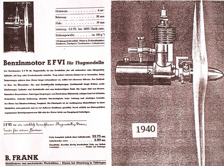
Now I'll bet you've never seen one of these before. Les writes:
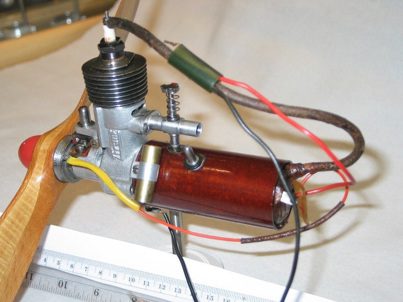
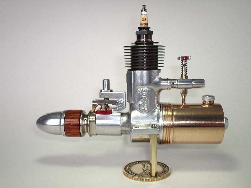
This is the German B. Frank Benzinmotor EFVI Bohrung 20 mm (bore .788"), Hub 19 mm (stroke .748") Displacement 5.980cc (0.365 cuin). I got the "prospectus" of the engine from Graham Podd and sent it on to Holger Menrad. He said if I'm patient, in the spring when the snow had subsided he would drive X amount of kilometres (he never told me exactly how many) to the site where the Frank engine was. He told me that he had only held a Frank engine in hand once in a life-time, indicating the rarity of the engine. The year shown for the engine was 1940, so with the war hotting up, I doubt much that many were produced. Holger Menrad's pictures and help were indispensable and paramount to the successful culmination of the Frank engine project. Regarding the pictures, three are of my reproduction. The one with the wires is of the original engine, taken by Holger. Take note that the original has the tank followed by the waxed in coil. German sparkers often combine the coil and tank in various fashion. This project like the Condor Midget was also long and drawn out because of the time consuming developemental work on ports, internals, patterns and castings. My engine follows the prospectus with just a tank scaled up to the right dimensioning. Those old brown condenser/capacitor tubes in that size are kind of hard to obtain. One more item of interest I'd like to run by you. I made a little mistake on the spark plug after I had already finished the inscription on it. Holger writes the following back: Dear Les
|
||||||||||||
|
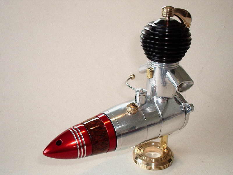
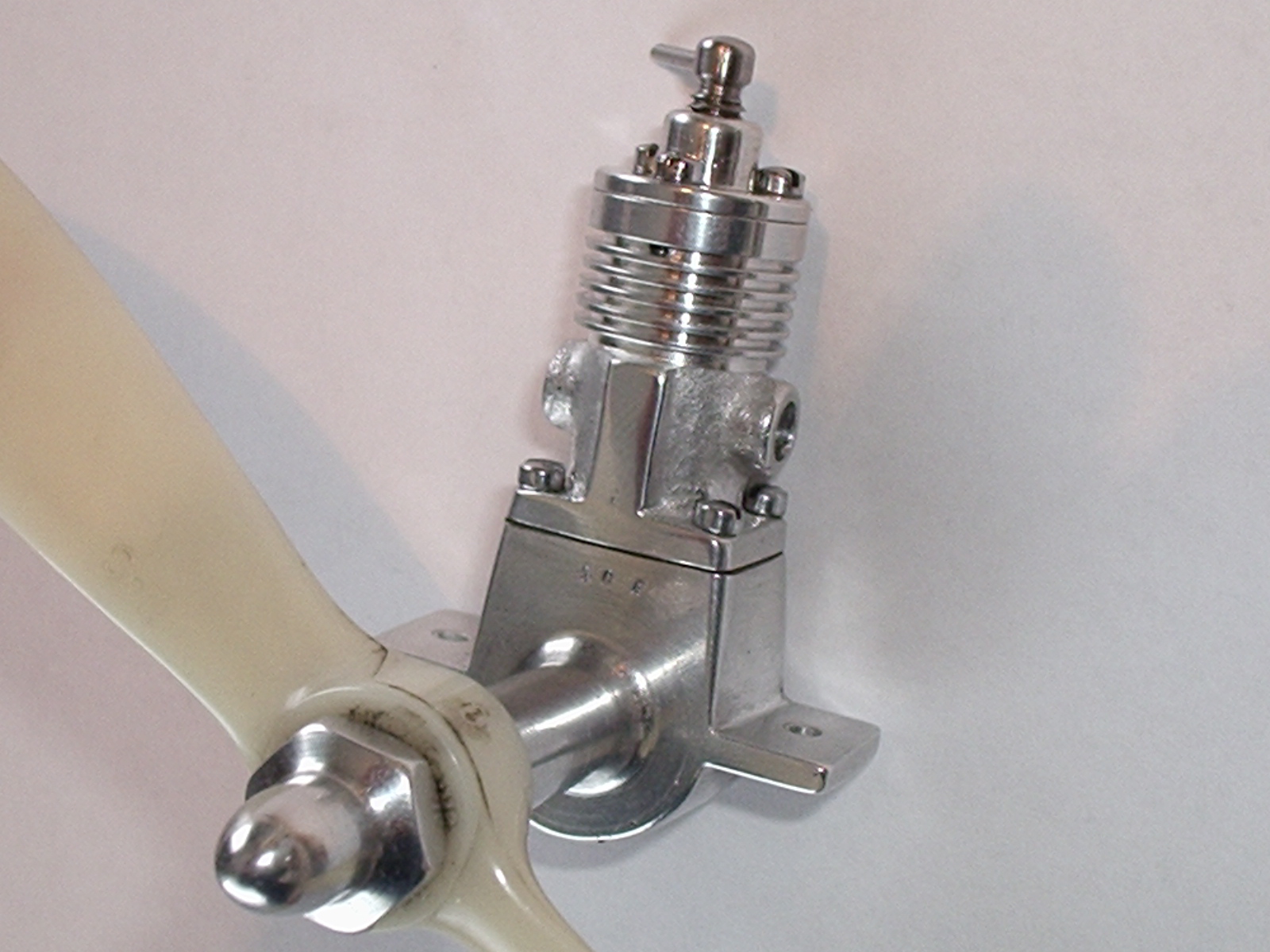
This is Les' rendition of the Japanese TOP .23, an ignition engine from the early post-war years. It was build from drawings Les made of an original engine. Shortly after he completed it, an article appeared in Model Engine World describing the engine and beginning a construction series for a(nother) full replica of it.
As expected, the engine bears Les' "trademark signature" finish, but take special note of the spark plug. This is shop made with a brass base that gives a beautiful contrast of metals. The insulator was turned from "Corian", a synthetic ceramic-like material that has been popular for kitchen tops (bad pun). It machines easily making it well suited to this function, although I've heard that it pits rather quickly with prolonged, hard running. As Les says, with the bullet shaped spinner and tank, it's hard to tell if the engine is comming, or going! |
||||||||||||
|
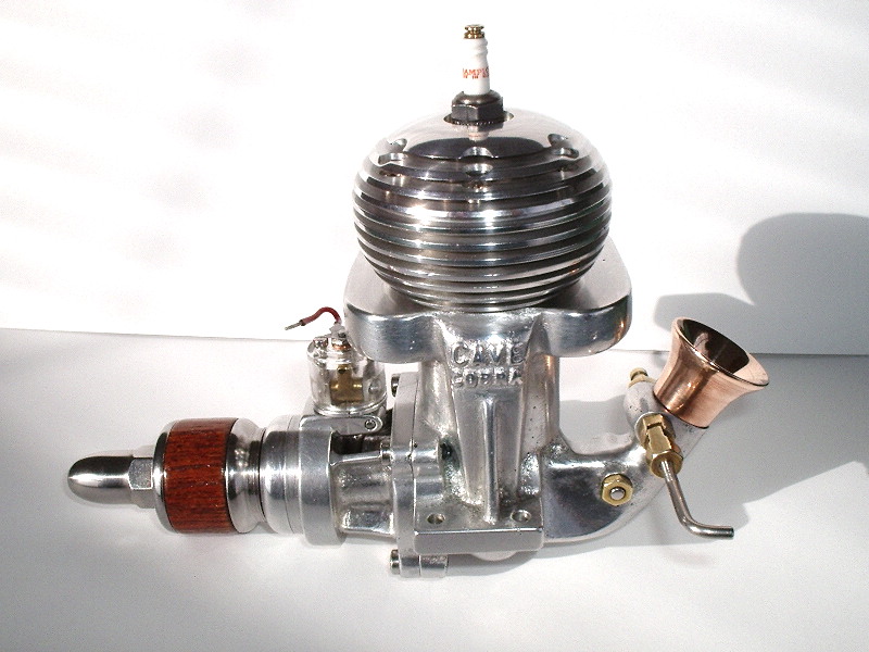
This is a Cave Cobra, a .60 cuin sparkie from the glory days of tether car racing. More details below in the section that shows the Cobra side by side with... |
||||||||||||
|
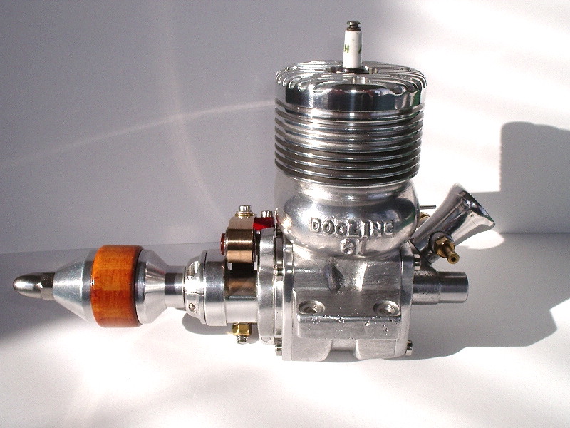
...Les' Dooling .61 replica. Even without the name on the side, who could mistake the bypass bulge on this engine. More details below. |
||||||||||||
|
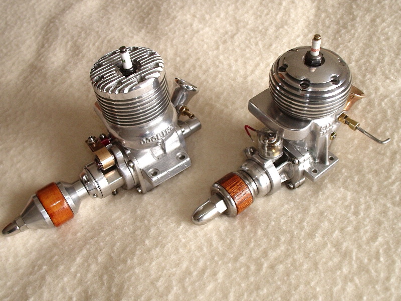
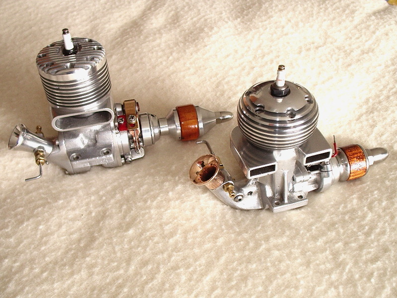
Both the Dooling 61 and the Cave Cobra share an era and a purpose: to drive tether cars around a track at speeds the eye has difficulty tracking. Les reports that the Cobra was made from a casting kit that is still available from Art Dekalb (see the Suppliers page). The trombone venturi was turned from a lump of beryllium copper, which Les says was "very tenacious to machine but well worth the end result". The 7-fin Dooling .61 replica was made from castings obtained from Denny Hitson—I don't know if these are still available or not. |
||||||||||||

|
Dropping in size a little, and not actually an internal combustion engine—or any kind of combustion for that matter—is this replica of an "expansion" engine of 1928 designed by Edward Pachasa, who was better known as Edward Packard of the Cleveland Model & Supply Company. The original plan appeared in American Modelmaker. For a time, Roger Schroeder of Classic Model Engines was able to offer kits and plans for the engine, and Les' example id from one of those kits. The plan, and the history behind it was serialized in Roger's regular "Engin-uity" column, beginning in the March-April 1969 issue of the Engine Collectors Journal. Compressed air engines like this were the only alternate to elastic power for model aircraft during the first quarter of the last century. While the air tanks were quite bulky, they and the engines were light and produced a truly remarkable amount of power—though like rubber, they tended to produce a burst of power that tapered to near useless towards the end of the run. |
||||||||||||
|
I dedicate this work with tribute to the late Miguel Devezeaux de Rancougne with an enormous thankyou to my good friend, benefactor and associate Graham A. Podd Who was ever so helpful, especially with the loan of the Etha diesel which was once in Miguel's collection. Without Graham's involvement, this endeavour would have never left the starting gate. Unlike the boys, I don't have an RPM gauge, but try to tune my ear to it while it is running. I've been doing this since I was ten years old and that was 60 years ago starting with an Ohlsson 60. The engine ran at a very respectable speed swinging a Top-Flite white nylon 11-7 prop. The needle valve wasn't at all sensitive and adjusted out nicely. Appearance and operation came up to my highest expectations. Best Regards, Les The Etha, while less well known than the Dyno, is generally accepted as being the first commercial compression ignition engine to appear on the market. |
||||||||||||
|
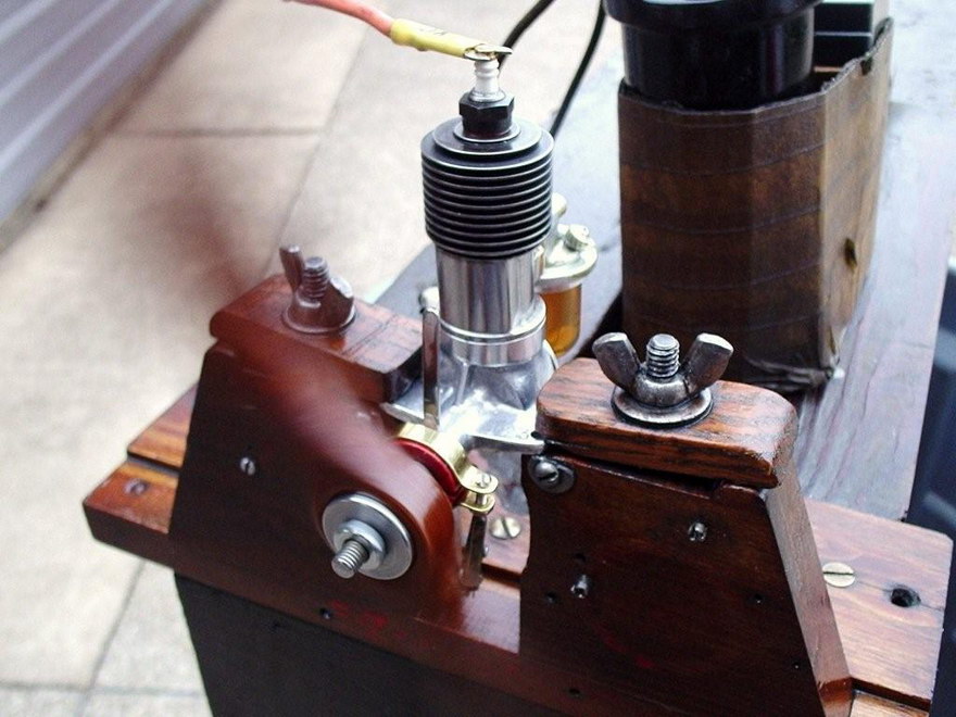
Ron, as you could readily see, there is much over-kill in the design, but I guess that was state of the art in 1938. You also see the reasoning I went for the blind bore on the cylinder. The crankshaft and front cam timing had to be done with ingenuity, because these were two of the parts that were missing from the series. It is interesting to note how things were accomplished on small engines back then when the hobby was in its infancy.
RC: The "Deller" appeared as a comprehensive set of vague hints on how to build a 1cc spark ignition engine in the English magazine "Newnes Practical Mechanics", starting in the January 1938 issue. For the full story, visit the Deller page.
The bore and stroke is 7/16" X 1/2" respectively. The plan called for a screw on head but I thought this was a lot of over-kill or over design which wasn't necessary, plus the fact you were getting into watchmakers work if you went this route. I queried Bert when I saw his finished Pepp. He told me it was finished with Birchwood / Casey "Perma Blue" Liquid Gun Blue. I went to an area gun-smith and he ordered me a 3 oz. bottle. This is what I used on the little Deller. |
||||||||||||
|
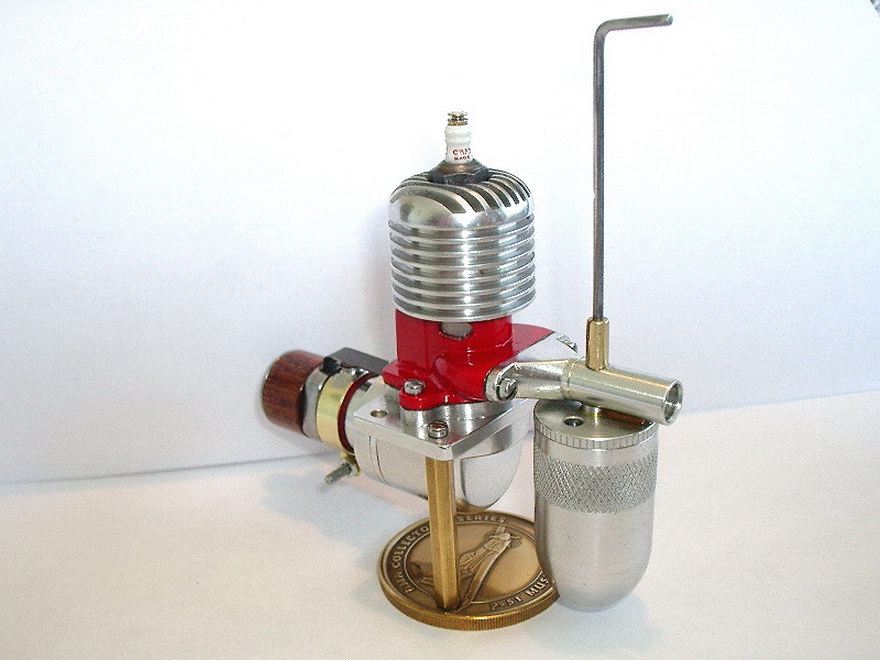
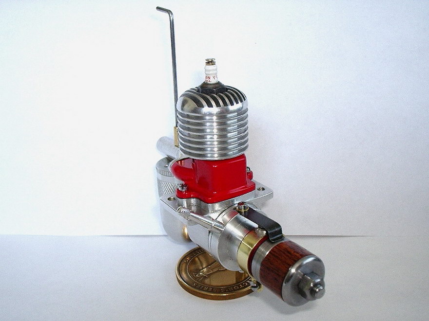
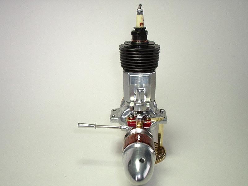
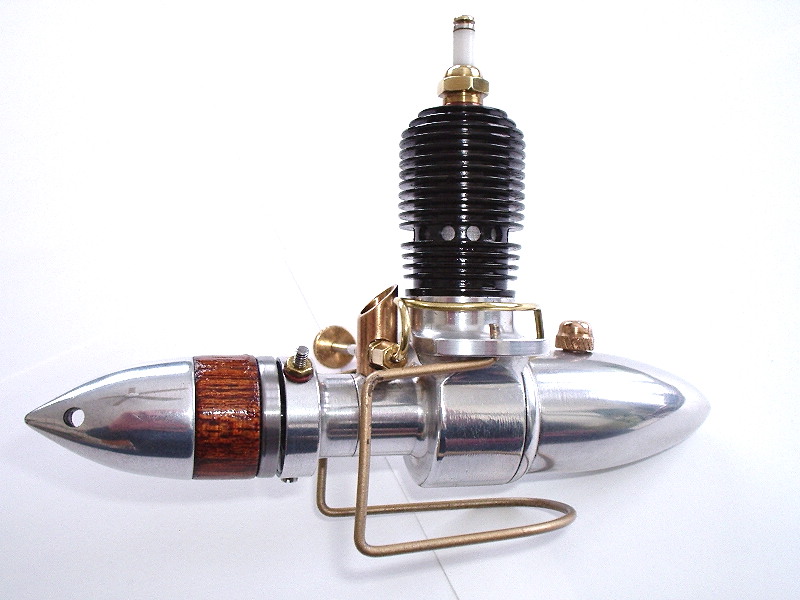
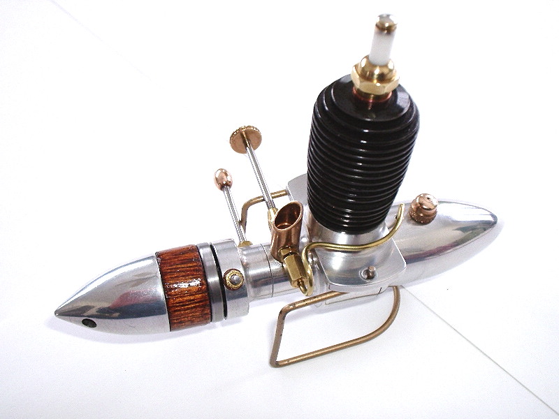
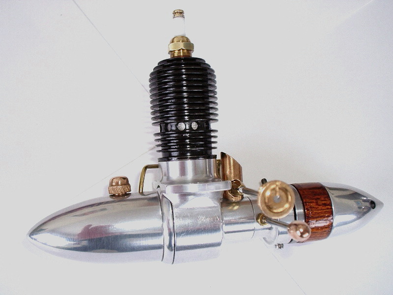
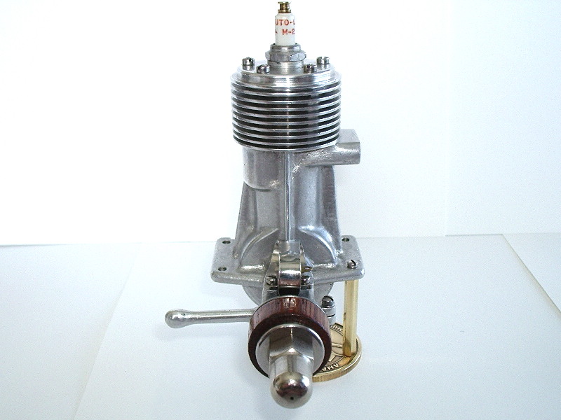
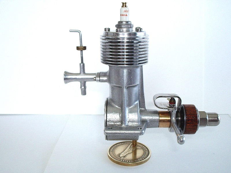
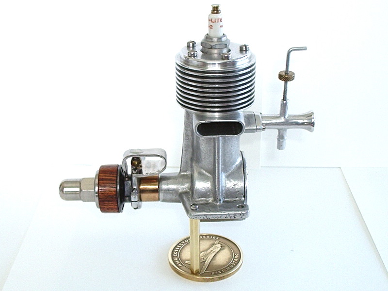
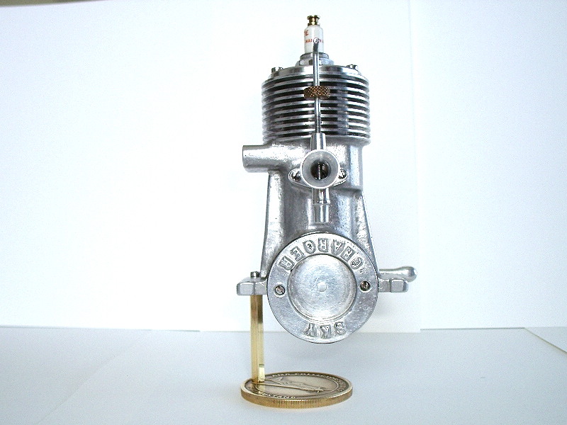
This is Les' rendition of the Sky Charger. The original engine, which was never put into production, was the product of Hollywood screen actor and model shop owner, Reginald Denny.
A copy of the design drawings found their way to erstwhile SIC editor/publisher, Robert Washburn, way back before he launched his magazine. At the time, Bob was writing for Home Shop Machinist. The full plans and his very detailed article on building the engine (and jigs to assist this task) were published there. Ultimately, it was the lack of editorial interest in IC engines in general at Village Press that led him to found SIC. Robert says 42 sets of castings went out after the build article appeared in HSM. As far as is known, apart from the ones Robert himself built, only two have been completed: Les' example seen here, and another by Ron Colona. |
||||||||||||
|
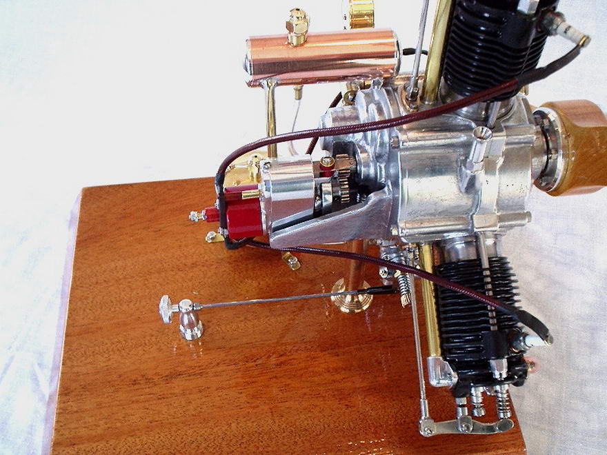
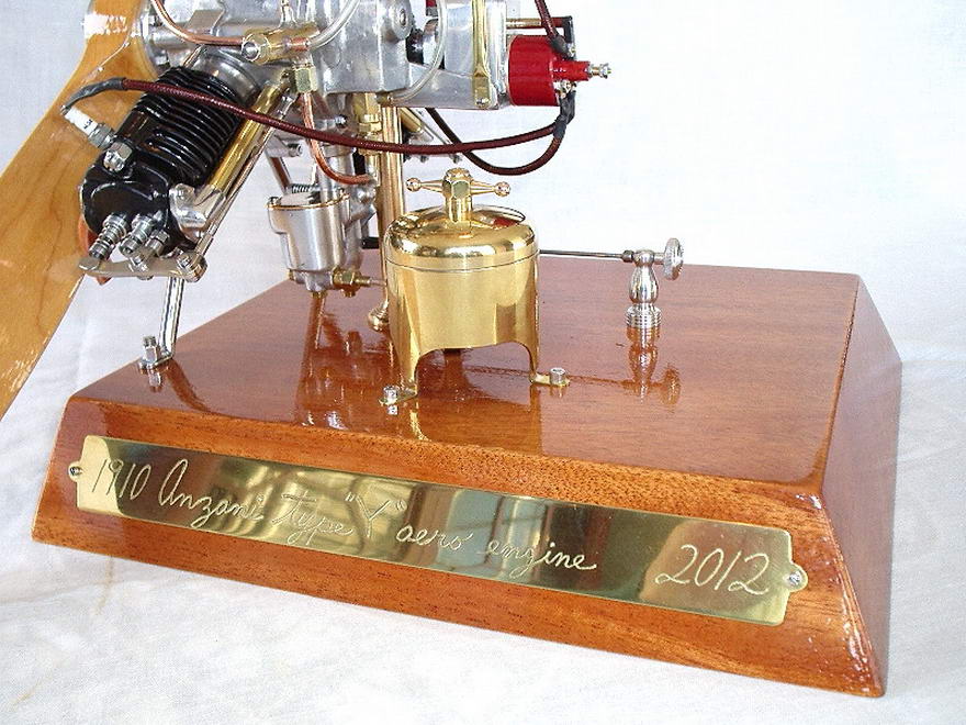
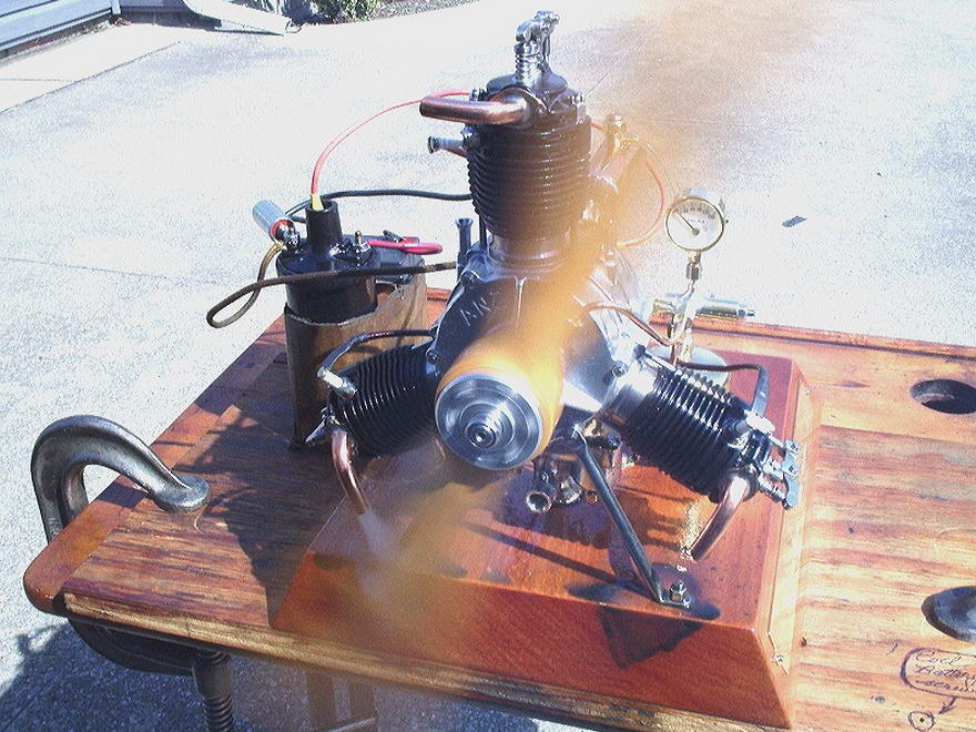
This is a 1/4 scale Anzani three cylinder, "Y" radial—as distinct from the Anzani three cylinder, "Fan" engine. With this engine, Les completes his renditions of the "collected works", as it were, of the late Les Chenery. The design is especially noteworthy for the way Anzani tackled the perennial problem posed the Big End of radial engines. The most common solution is the "master/slave" rod design. While the position error for the pistons connected to the slaves can be compensated for, the most correct (and complex) solution is to use "slipper" big end segments, concentric with the crankpin. Les comments that successful completion of this mechanism was one of the high points in building the engine. An even more complicated slipper Big End, comprising two concentric tracks, was used on the Le Rhone nine cylinder rotary, as detailed in Aviation Engines, by Pagé. Back to Les' engine. The drawings (dated December, 1992) and castings had been sitting around the house for 16 years, so Les decided it was finally time to make a start. On one of the trips to England made by Les and his wife, they had the opportunity to spend a day with Les Chenery and his wife Alice. This made a lasting impression which has finally resulted in the construction of all six of the plan sets designed and drawn by Les Chenery. Later, Les and his wife received a letter from Alice Chenery in which she described her husband's fascination with the real, full-size three cylinder Anzani Y type Aero Engine that is mounted in the nose of the Depperdussin which forms part of the Shuttleworth Collection. This was his inspiration to design and build the 1/4 scale model. Les Chenery was allowed to take any measurements that were required, so it is fitting that some of his models were donated to the Shuttleworth collection. Les' attention to detail is most clearly evident in the bottom four photos which show the engine fully completed, and running. Take special note of the oil tank with domed brass ends, and filler cap, which feeds a manifold that supports an oil pressure gauge. Behind the engine, on the baseplate (a work of art by itself), is a device which reminds me of an old glue-pot (the horsed hoof glue variety), except no glue-pot was ever that shiny. It is complete with a rather maritime cap lock. The device at the rear of the baseplate is an extension to the carburetor fuel regulator. As he does on all engines, Les takes care to use metals and other materials which provide color contrasts. For example, the red distributor cap, and the oil tank mentioned earlier. Have a close look at the other engines on this page for more examples of this attention to eye catching detail. And finally, showing this is no mere show pony, we see the Anzani doing what it was always intended to do, run! |
||||||||||||
|
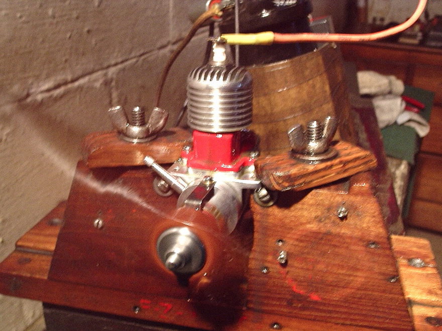
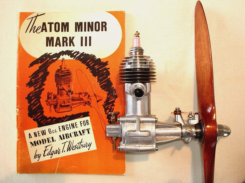
Like many other model engineers, Les has built the Westbury Atom Minor Mk III, from the Atom Minor book. His castings were obtained in the US about 1997 from Fred Ellis' Power Model Supply (not to be confused with Coles' Power Models). Fred Ellis died in a firework explosion and fire at his shop circa 2000, so that source is no longer available. Although it is possible that Ellis had his own patterns, his catalog lists a number of other ETW casting sets, all of which were available from Woking Precision (UK), so Fred may have been their US agent. Woking changed ownership in 2003, but chucked it in 2006. However, the Woking's patterns and stuff were bought up by Hemingway Kits (UK) who plan to improve the quality as time and demand dictates. There is nothing basically wrong with the Woking castings, although registration of the bosses on crankcase and covers is a bit coincidental. That just means more care, attention, and experience are required to achieve the results obtained by Les, and Jan Huning. In fact it was in response to Jan's report that that crankcase ran hot that Les decided to fire up his Atom and check the 'case temperature. Les reports that after a good run, he put a finger on the case, but it did not stay there long! The question remains, why? For the test, Les used Coleman's Lantern Fuel, mixed 3:1 with #70 weight oil. This is a petroleum naphtha product, historically known as "white gas", which is exactly what was traditionally used for sparkies in the old days, with a high combustion temperature and no additives, like tetra-ethyl lead. As we see here, Les' Atom Minor seems to like the stuff, just fine. |