 |
Westbury Whippet Project:
|
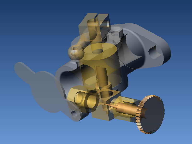
The Whippet carburettor is similar to many of Westbury's other designs, being of a type that he describes as "compensating". It is really quite simple in concept and construction, so the text below will concentrate mostly with how to mount irregular parts for second operation machining, and how to deal with unpleasant surprises.
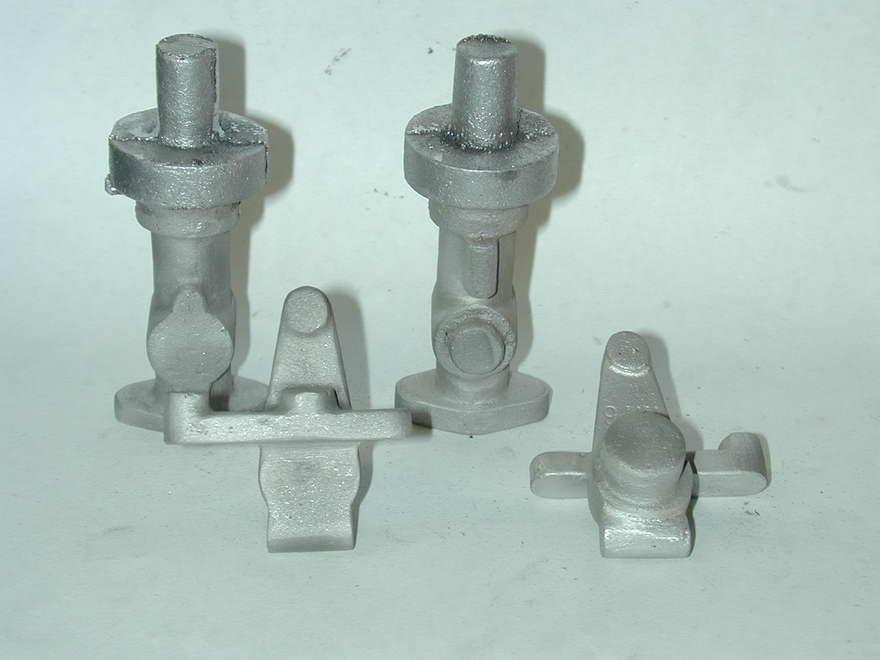
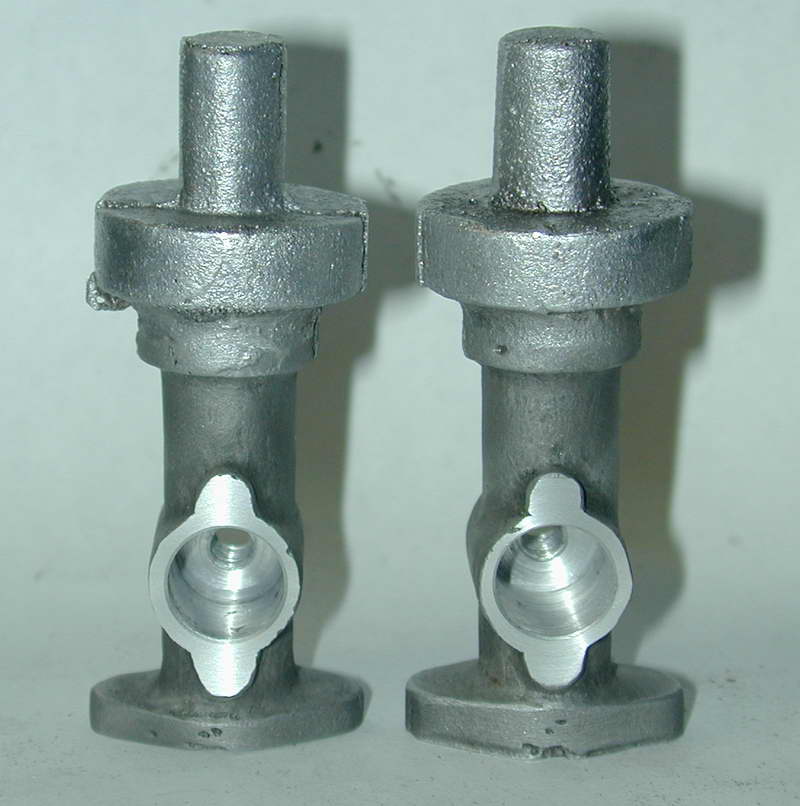
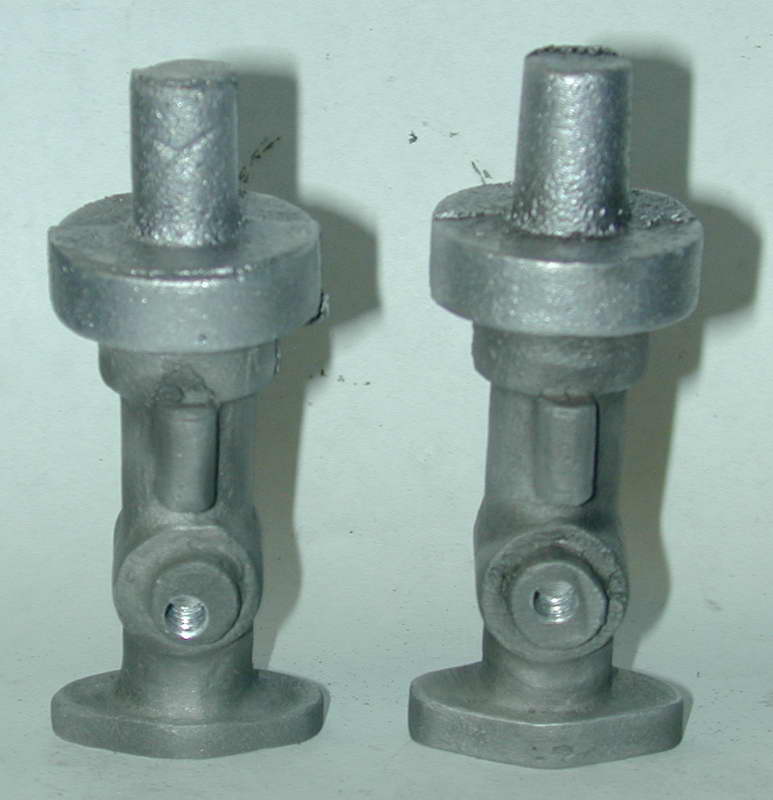
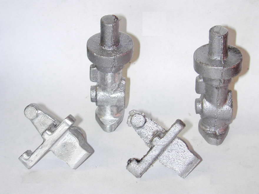 The main casting for the carby is, shall we say, a bit rough, as is the timer casting. So expect to spend an hour with riffler files and maybe a Dremel ® hand-piece making it more carby like and less blob shaped. These shots gives an idea of the before and after state. The first shows a raw casting (right) and one that has been fettled. File work like this can be hidden easily with a spot of sand blasting, or less easily by pounding on it with the bristles of a wire brush, or "file card". The second shot shows the castings after sand blasting.
 The pattern maker chose to split the pattern with a top/bottom orientation rather then left/right. Either choice would work, and both offer potential problems when registration is not perfect, though I think the choice made offers the greatest potential for grief. Notice that the boss on the bottom into which the fuel metering jet will screw is badly aligned in relation to the boss on the top which will locate the throttle barrel. They should be concentric, but as the top mounting face has side bosses for attachment screws, it is the most critical. So we must use the top position and live with wherever a concentric hole will emerge below. Note also that the foundry has liberally applied their grinding wheel to what will become the mounting face of the casting, removing rather a bit too much for comfort on the lower of the two.
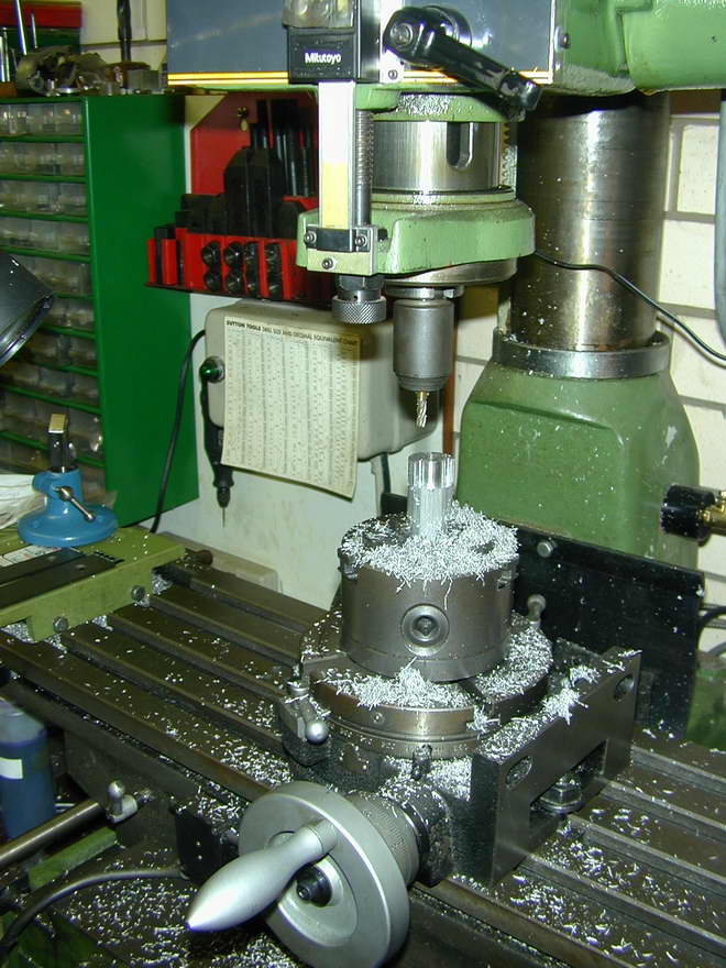
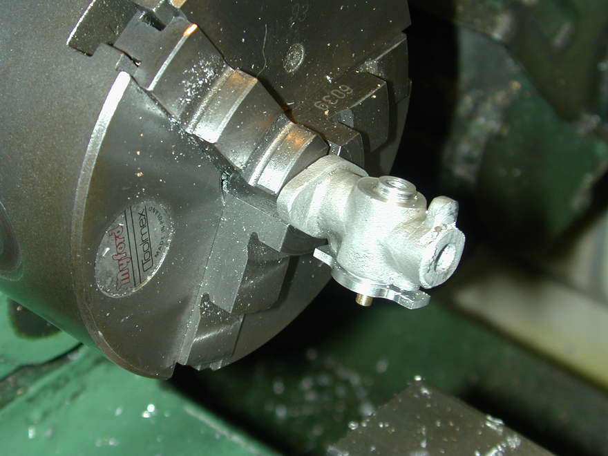
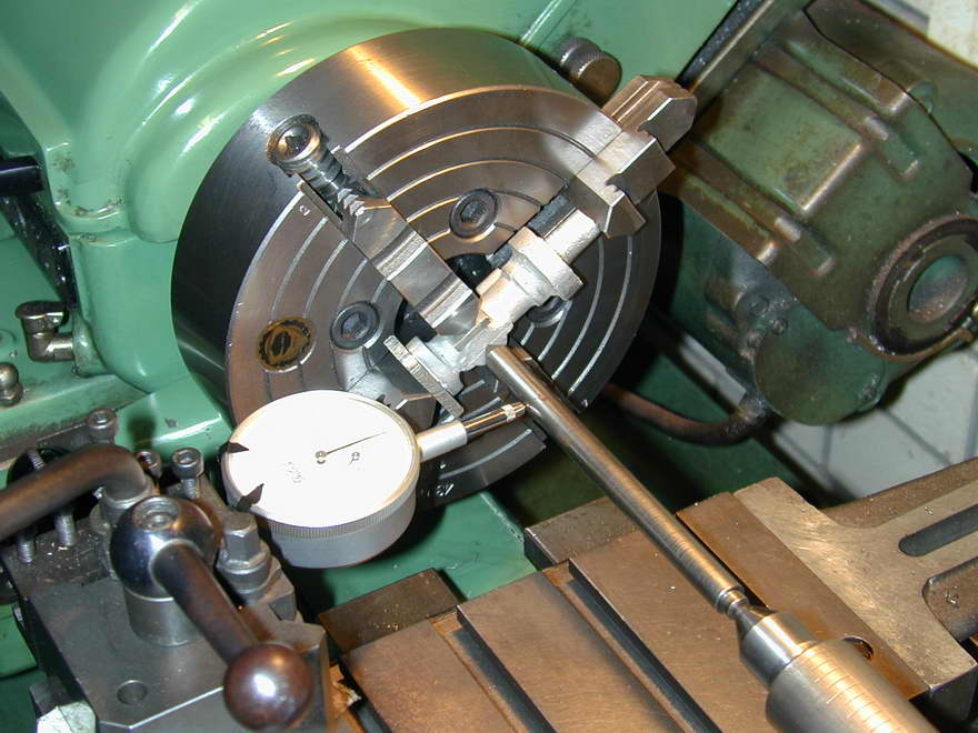 Some marking out is essential here to establish the best compromise location for the barrel bore that centralizes it in the boss and carburettor bore axis. The casting is then gripped in the four jaw chuck, aligned so that the mounting ears are level. The marked position is then set on the lathe axis with a wobbler. The casting can then be faced, blind bored, and finally drilled through and tapped (3/16 x 40TPI ME series) for the jet assembly. I made a bit of a booboo here by following the plan dimension for the depth of the bore rather than measuring the casting. Had I done this, I'd have found that the casting was way over size and that the bore should have gone about 50 thou deeper. I got away with it, but the passage in my throttle barrel is very close to the bottom edge of the barrel. Lesson: assume all dimensions of the castings are wrong and make liberal measurements and notes on the plans.
 |
 |
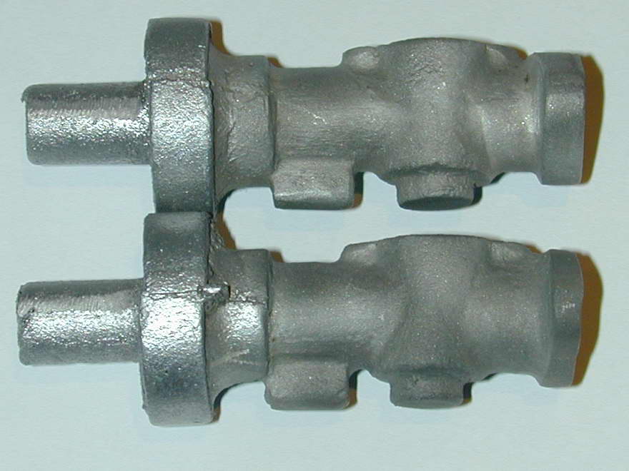
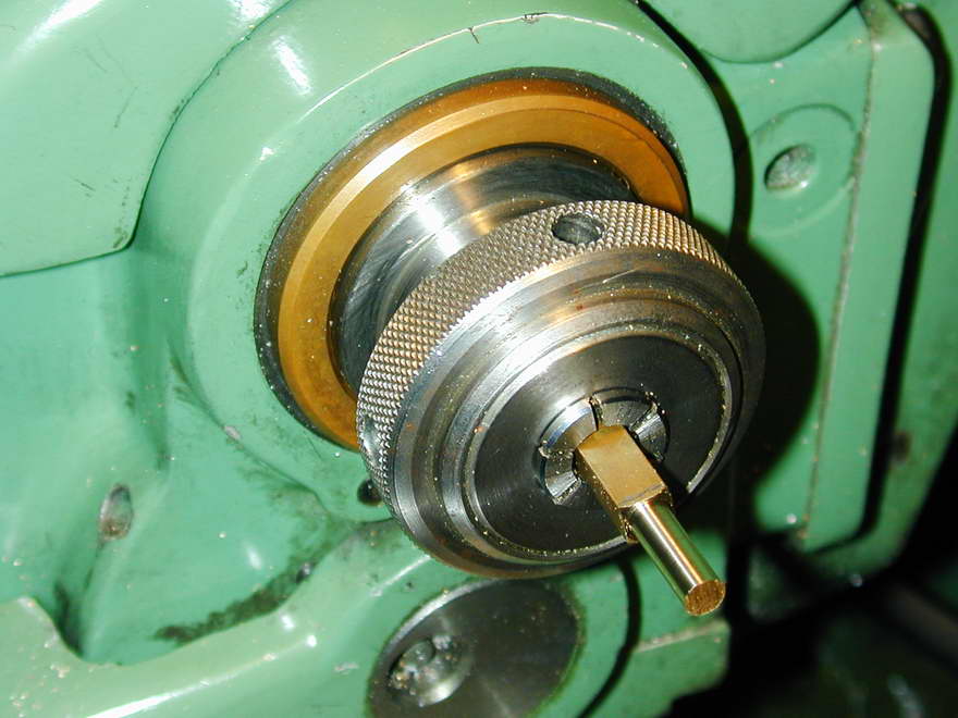
The second two photos above show how well the bore is centered in the cover plate mounting boss, how badly the concentric jet hole is located in the underside boss, and how variable this is owing to registration of the pattern prints.
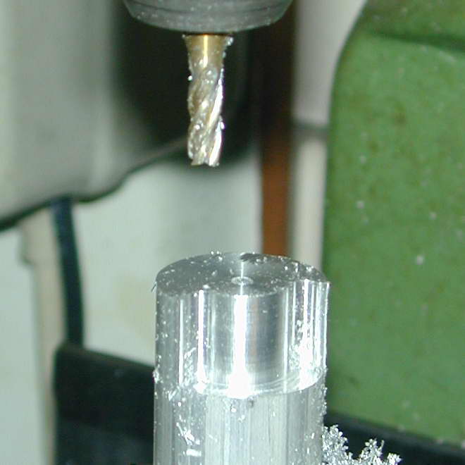
 The problem is rather cosmetic in nature, and hard to see when assembled, but I chose to mount the casting on a stub mandrel and clean up the bottom of the casting so that the boss appeared concentric with the tapped hole. The mandrel is the brass stock supplied for the throttle barrel. I've skipped showing the machining of this part; it's too simple. But note that is will be bored in situ with the main casting in a later step.
 |
 |
 |
The cover plate was profile milled onto the piece of 1" bar stock supplied with the kit. The actual purpose of this material was a mystery, but it has seen service as the mandrel for machining the piston, and now as the cover plate. The other possibility was using the end of the casting that will be cut off later, but the alloy machines so badly, the less I have to do with it, the better. I've profiled enough stock to permit two cover plates to be parted off. The mounting holes are spotted through the "ears" into the main casting and tapped 8BA. Finally, the ears are profiled with filing buttons to a close approximation of the corresponding casting bosses.
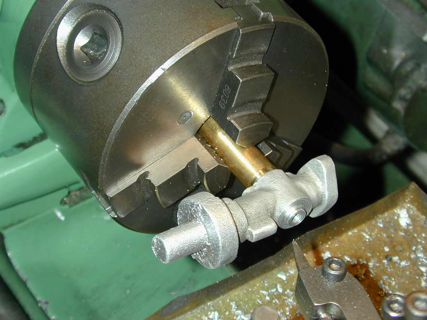
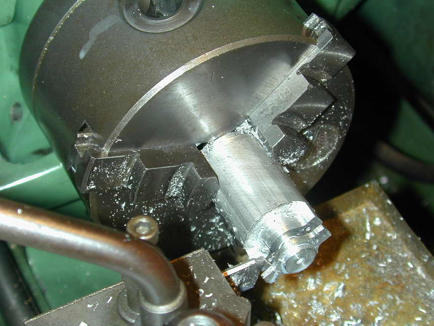
 For the next operation, the barrel is clamped into the casting with the cover plate using a washer interspersed between the two to press it firmly to the bottom of the bore. The casting is then chucked by the cast stub and adjusted in position until the bore is centred on the flange axis intersection. This induced an off-center exit for the bore which may have been avoided if I'd used a four-jaw chuck instead. The assembly was then blind drilled 1/4" for sufficient depth to exit the casting when parted off. The mounting flange was next faced back to 1/8" thick (a bit less in the case of the "thin" one). A light witness mark was then made with a 5/16" slot drill on the finished face and the opening taper turned 20° until the taper just met the witness mark.
The last operation for this set-up should have been to part off the carby from the machining stub. Part way into this, the chucking stub broke off! This was a bit of a surprise as the stub is about 3/8" diameter and you don't expect such things to break under cutting loads. Examination of the fracture showed a distinct granular, almost crystalline face. Mumble, grumble, mumble... Guess you're as sick of me complaining about the alloy quality as I am of working with it. The second one was sawn off.
 To finish the inlet side, a 1/4" mandrel is is wrung into the brass part of the bore allowing the casting to be bell-mouthed and faced. The exit was noticeably off center, but with some creative turning and polishing, it was possible to obscure this small defect adequately.
 |
 |
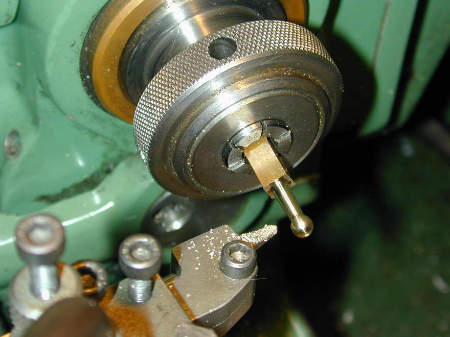 |
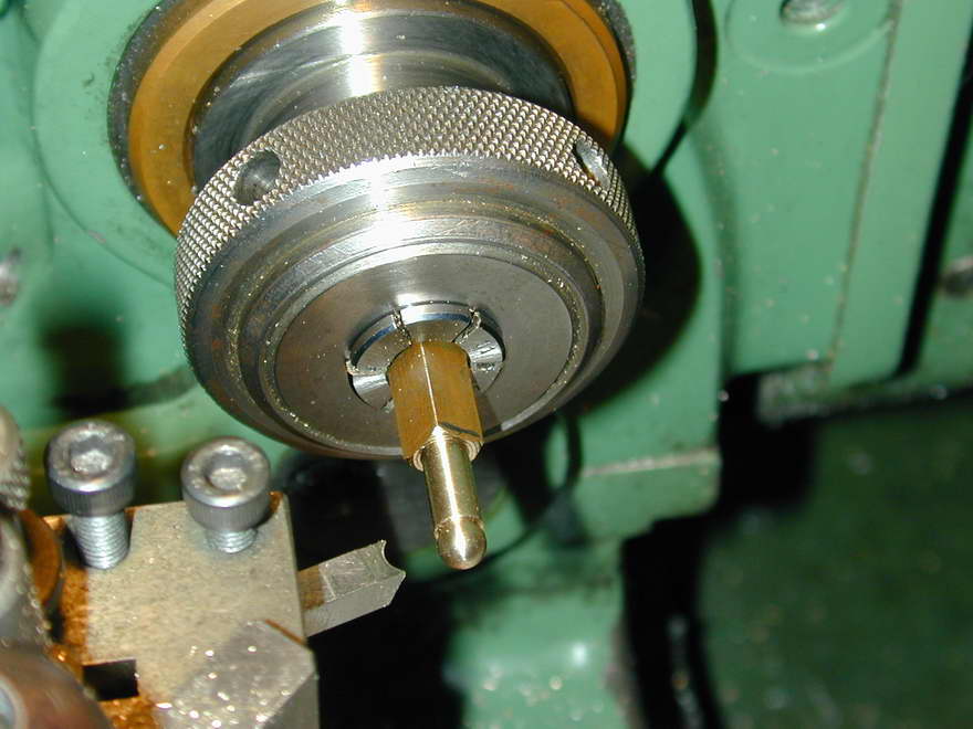
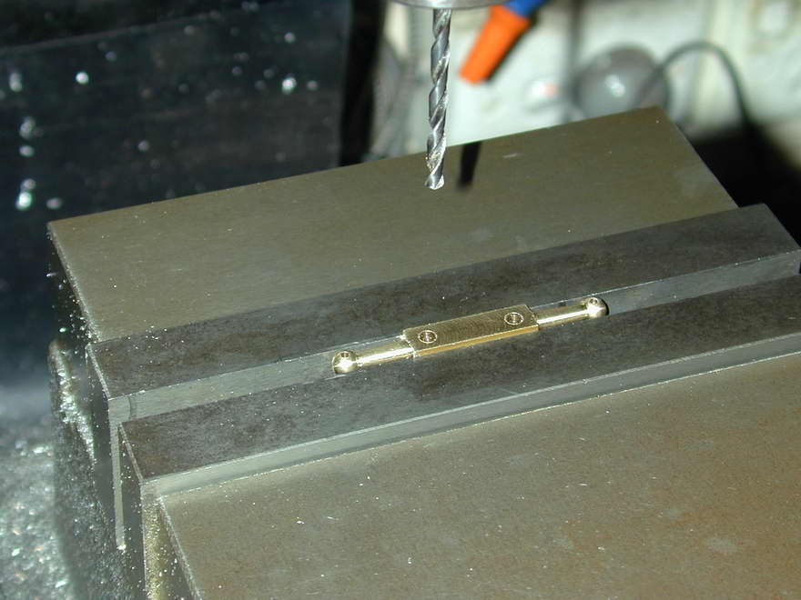
The throttle arm is simple turning and drilling. The photos show wilful abuse of a perfectly good collet to hold square stock centrally for forming the ball-end and taper turning the arm. As the cuts are light, I think this rather bodgie mounting is acceptable; saves grunting the four-jaw chuck from the bottom drawer. The end was formed with a form tool ground off-hand in HSS with a chain-saw sharpening stone in a Dremel tool, using a drill shank to check size and shape.
 |
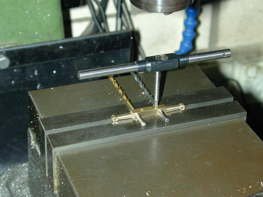 |
Two arms were made at the same time and finally milled, drilled, and tapped for the clamping bolt and actuating cable attachment. They were then separated and the end slit per the drawing.
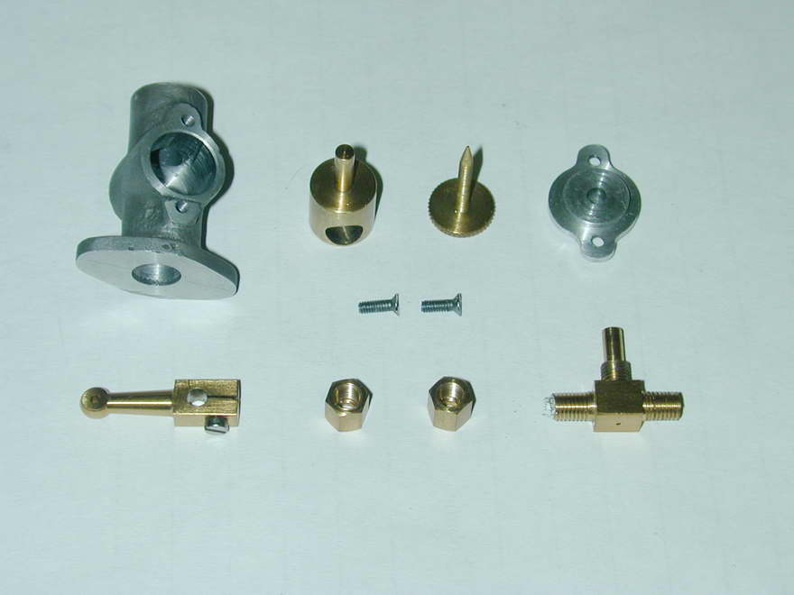 The remaining parts for the carby are simple turning, drilling and tapping. I've chosen to make the parts per the drawings, so the fuel line will be solid pipework, secured by a gland-nut. A special stub pipe and ferrule can always be made to attach a conventional plastic tube for testing purposes. The gland nut on the other end is packed with Teflon tape (plumbers' tape) to provide a seal around the needle thread. Note too the fine "compensating" hole in the bottom of the inlet "T". For the life of me I can't see why this is not going to leak fuel, but I've drilled it anyway. Worst comes to worse, it can always be invisibly soldered over.
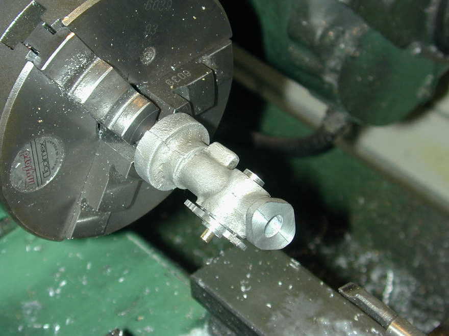
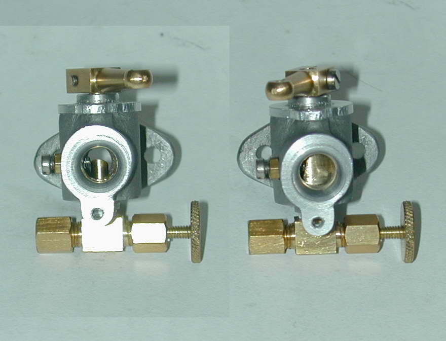 This shot shows a small addition to the carby as published, taken from the ETW Seal carby design which is very similar. On the left, a hole has been tapped for an 8BA screw and locknut. The hole is positioned so that the tip of the screw acts as a fixed stop for the fully open position, and an adjustable stop for the closed setting. At this stage, the mounting holes have been drilled, but the left lug still needs to be machined away vertically to bisect the hole. This is because the block provides only three attachment holes to share between the exhaust pipe and carby flanges. A bit ugly, but it keeps things compact. The unit also needs a choke plate filed up and fitted. I hate little filing jobs like this.
Conclusions and Observations
As you can't help noticing in the above picture, the exit of the inlet hole is very badly off-center in the casting, although well centered in the flange end of the casting. I strongly recommend that before anything else, the casting be gripped in the 4-jaw chuck so the entire end can be machined into a chucking stub that is concentric with the inlet tube of the casting.

|
This work is licensed under a
Creative Commons Attribution-Noncommercial-Share Alike 3.0 License. |