CamCalc Mk II
![]()
 This page will generate a table of lift figures for a harmonic cam from
values entered in the fields below. The lift table is used in machining
the cam profile by the milling method
(see Page 7 of the Feeney
Construction series for a description of this process).
The following links provide more detailed information.
The links from the parameter labels explain what is required for each.
This page will generate a table of lift figures for a harmonic cam from
values entered in the fields below. The lift table is used in machining
the cam profile by the milling method
(see Page 7 of the Feeney
Construction series for a description of this process).
The following links provide more detailed information.
The links from the parameter labels explain what is required for each.
 Some brief notes on how this all works.
A (thankfully) brief technical explaination.
The Effect of Tappet Clearence.
Source Code for the Terminally Curious.
Acknowledgements on the genesis of this tool.
Some brief notes on how this all works.
A (thankfully) brief technical explaination.
The Effect of Tappet Clearence.
Source Code for the Terminally Curious.
Acknowledgements on the genesis of this tool.
Warning!
This page has been validated with IE6, IE7, and Firefox 2 only. Other browsers may have problems. Please email me if you encounter any.The meaning of the input variables and their limits are listed below.
You can also click on the label to the left of any input field to find out
what and why it is. The form does reasonable input variable validation,
as does the underlying program that performs the math, but I'm sure it's
possible to fool it into producing rubbish if you try hard enough.
Note: CamCalc assumes the cam is used in a four-stroke cycle
engine where the cam gear rotates at one-half engine speed. Hence the
value entered here is halved to calculate angular velocity of the cam.
Textbooks tend to give examples quoting the camshaft speed—reasonable
as the textbooks generally are considering only the cam and follower,
not their possible inclusion as part of a four-stroke engine.
So be warned if you are validating output against such a text.
The parameters may be input in metric or imperial by selecting the
appropriate Radio Button at the top of the form. The only effect is
in regard to how the values in the lift column of the table is
formatted, and how velocity and acceleration are presented. Imperial
users will see lift as thousandths of an inch, rounded to three
decimal places, with velocity and acceleration in ft/sec, and
ft/sec2. Metric values for lift
will be displayed rounded to two decimal places, with velocity and
acceleration in meters/sec, and meters/sec2.
Acceleration due to gravity should be the same in both cases, modulo the
internal approximations for acceleration due to gravity used.
The basic concept for this program came from an article by Rodrick
Jenkins called Cam Design for Four-stroke cycle Engines other than
Radials that appeared in Strictly
Internal Combustion Magazine (ISSN 10446567), Volume 3, Issue #18,
page 3. Without this article, the tool would probably not exist—even
though the algorithms used now are very different from those employed
by Mr Jenkins. His published program (in BASIC, a flawed and dangerous
computer language when used for non-trivial applications) generates
the correct values for tangential lift of a "mushroom" cam follower
on a harmonic cam, but the acceleration and velocity figures are wrong.
Nevertheless, v1.0 of the program enabled the cams for the Feeney to be
milled. V1.1 uses equations from an undergraduate mechanical engineering
text and the implementation at least produces the same results as the
worked example in the text: Bevan, Thomas (ed.):
The Theory of Machines, p288 et seq.
There are three basic types of cam shape: Parabolic, Cycloidal,
and Harmonic. The general shape of the lift and velocity curves with
respect to rotation differ for the three. The CamCalc program currently
handles only harmonic cams. These have six parameters:
Some cams are designed with an amount of "dwell" by modifying the nose
to introduce a period where maximum lift is sustained. We will not
consider these here.
The rising and falling flank radii are generally the same.
Regardless, all parameters are related such that there is only one shape
that fits all. Change one, and one or more of the others must change too.
Modelling a physical thing mathematically can present challenges when the
user's inputs "don't add up". This could be due to rounding errors of
decimal values, or even a set of values that contain an irrational number!
Jenkins apparently side-stepped this potential problem by omitting a
parameter which, even though it is probably known, can be readily
calculated from the remainder. In this way, his model must be correct
and the figures derived from the model will be consistent—I'm making
this assumption as the only rational reason he could have had for always
calculating the nose radius even though it would almost certainly be known
by a user. Alternately, the cam operating angle could be omitted and
calculated from the others, or the flank radii, given base circle,
nose radius, lift and opening angle.
After the cam parameters are known, our program is going to calculate
a table of rotation verses incremental cam lift for a fully tangential
follower (often called a mushroom follower) whose axis is in line with
the rotational axis of the cam. This is useful and essential when making
a cam by milling as described in Page 7 of
the Feeney Construction series. Given the lift, velocity and
acceleration can be calculated by applying the angular velocity,
or averaging for a specific cam rotation speed. The SIC program used
averaging, and managed to get it rather wrong, IMHO.
The acceleration figures produced by the tool here could be
useful in determining the spring rate required to keep the follower in
contact with the cam, given the mass of the components being actuated,
but only if the actual cam follower is fully tangential—ie,
a flat surface broad enough so that the edge never rides on the cam. The
math used to calculate lift for other follower shapes—typically point
contact (seldom used), or roller type followers, is well known, I just
haven't implemented it, yet. Many model engines use a spherical follower
(or something approximating spherical). This is equivalent to a roller
follower and would produce very different lift, velocity, and acceleration
curves, which are what one would require to estimate the valve spring rate
for such a design, but the lift figures for this type of follower could
not be used to produce the cam by milling.
All this is to say that the last three columns in the table produced
by the CamCalc program in it's present (version 1.1) form, should be taken
with a dose of salt. The program, like Mr Jenkins', will give the minimum
diameter/width for a mushroom follower that will maintain fully tangential
contact. Your design may, or may not have sufficient room to fit such a
beast. If I get bored, I may modify the program to accept different sets
of input data, generate tables for roller type followers, accomodate an
offset follower axis, different radii for rising and falling flanks, etc.
But don't hold your breath.
This clearance is very necessary in order to account for thermal expansion
of components, principally the valve itself. If this is not done, expansion
may lift the valve off its seat—not good for hopefully obvious reasons.
The cylinder will also expand, although in most geometries, this will tend
to compensate for valve expansion. But keeping the valve head firmly on its
seat when not "on the cam" is of prime importance, so the tappet clearance
is very necessary. The amount of clearance depends on many factors, but
given the sizes and materials typical of our model engines, 0.002" to 0.005"
is common.
By adding tappet clearance, there will now be a delay before the follower
contacts the flank (the red lines). In the diagram above, a clearance of
0.010" has produced the rather extreme reduction of almost 50°
in the cam opening angle. This represents a 37% reduction from the design
figure. If clearance in the drawing—which depicts the Westbury
Kittywake exhaust cam—were reduced to the required 0.004",
the actual reduction in the cam angle would still be some 14% or 20°
with the cam opening angle being 114.7° compared to the 135°
we thought we had.
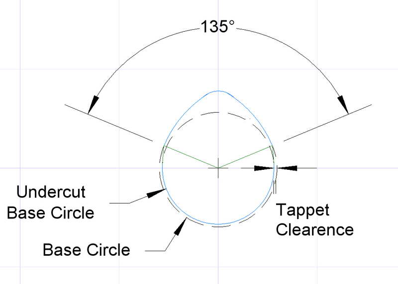
One cure for this problem is to relieve or undercut the base circle
by the required tappet clearance. Note we are not reducing the base circle.
The cam flanks must still be tangential to the base circle in order to provide
the required opening angle. The relief is introduced by a cutting a tangent
between the end of the cam flanks on the base circle radius and the relieved
base circle (as shown in this diagram). How accurate do we have to be? Well,
at model sizes, it's all a bit approximate unless you are a serious performance
builder—and hence unlikely to be reading this for more than idle curiosity
The actual tappet clearance will vary with the engine's operating
temperature, and to a degree, so will the cam durations. But from the
figures shown above, the need to introduce an allowance for the tappet
clearance in the base circle while maintaining the correct location of
the flank ends should be obvious.
There is another cure: increase the "distance" between the open and
close points to compensate for the tappet clearance. This is not as "hit
and miss", if you'll pardon the pun, as it sounds, especially if you can
model the thing in a CAD package. All the usual problems of juggling flank
radii and nose radius to achieve the new cam angle still apply, and the
acceleration figures produced by CamCalc will go out the window as they
assume tangential cam contact starting at the flank to base circle
intersection point. In both cases, there will be a hammering effect as
the clearance is taken up. That produces mechanical noise, which some
believe adds to the charm of the running engine!
Enough requests to fix these limitations were received to do a rewrite.
For this, PHP was chosen. This means that the code MUST be served by a PHP
enabled server. The other choice would have been ECMA script (ne Javascript).
While this would have permitted off-line use totally inside a browser, the
PHP option was chosen as being simpler due to cross-browser script language
issues and the impact this has on testing.
If you want to see the PHP code, just do a "view source" on the pages involved,
or issue a "wget". For the Java source, see here.
The approach used in the CamCalc program was derived from an article
written by Mr Roderick Jenkins that appeared in in Strictly Internal
Combustion magazine, Volume 8, Number 18, dated Dec 1990/Jan 1991.
Back issues of SIC are available from the
editor/publisher.
Base Circle Radius
This is the radius of the circle where the cam follower rides when no valve
lift is being applied. The program does not recognize "undercut", but you
can subtract this if you wish when machining your cam. Enter as
inches or millimetres.
Valve Lift
This is the total amount of lift the cam will apply to the cam follower,
above the base circle radius. Enter as inches or millimetres.
Cam action angle
This is the number of degrees from beginning of lift to the end
(in between the points where the flank radii tangentially touch the
base circle). Note this is not the crankshaft rotation figure sometimes
used when quoting timing figures for four-stroke cycle engines;
that would be twice the cam action figure. The program will only accept
a maximum value of 180 degrees for this parameter. If you don't know it,
but do know the nose radius, take a guess starting at say 130 degrees,
then adjust the figure until the calculated nose radius matches the
one for your cam.
Flank radius
The program will assume that both rising and falling flanks are the same,
then use this figure, together with the base circle and lift to calculate
the nose radius required to tangentially join four circles into a
continuous harmonic cam. If you want a flat sided cam, just enter a very
large figure for the flank radius. Enter as inches or millimetres.
Table row increment
This is the interval in degrees between rows of the generated table.
You should set it to the value you want to advance your rotary table
between cuts. The program requires integers for this figure,
so decimal parts of a degree will be ignored.
Engine Speed
This parameter has no impact on the lift calculation. You may ignore it
if you only want a lift table. Once the lift figures have been calculated,
the instantaneous velocity and acceleration of the cam follower can be
calculated for a given a specific engine speed. The acceleration can be
used to select the correct "rate" for the valve spring, provided the
actual engine cam follower is a mushroom (see Theory).
The velocity and acceleration values are plotted against the angle of rotation
to assist you in visualizing what your cam is asking the valve train to do.
Engine Name
This parameter has no impact on the lift calculation either. Any text
you supply will be printed at the top of the results page and may be
of use in reminding you later what this set of figures applies to.
Keep it brief, eg: ETW Kinglet: Exhaust.
Operation
The first four parameters are mandatory. If omitted, the table increment
will default to every degree and the engine speed will be set to 5000 rpm.
You'll notice that the nose radius is not requested.
This will be calculated from the lift, base circle, flank radius, and
cam action angle figures to ensure that the cam being modelled is
physically accurate, which it might not be if you were permitted to
input a nose radius as well. The generated table will show the
calculated nose radius used to enable you to cross-check that it
is the value expected.
Acknowledgements
Theory
The Effect of Tappet Clearance
 Now for a small dose of pragmatism. Anyone who has seen a New-In-Box model
four-stroke will probably have noticed the little bag of tools that
accompanies it. One of these tools is a feeler gauge that is used to set
the tappet clearance. Generally, this is performed by loosening the
tappet adjusting screw in the rocker and adjusting its position until the
feeler gauge slips firmly but freely between the rocker nose and valve top.
Obviously this introduces some "slop" into the train of parts that actuates
the valve.
Now for a small dose of pragmatism. Anyone who has seen a New-In-Box model
four-stroke will probably have noticed the little bag of tools that
accompanies it. One of these tools is a feeler gauge that is used to set
the tappet clearance. Generally, this is performed by loosening the
tappet adjusting screw in the rocker and adjusting its position until the
feeler gauge slips firmly but freely between the rocker nose and valve top.
Obviously this introduces some "slop" into the train of parts that actuates
the valve.
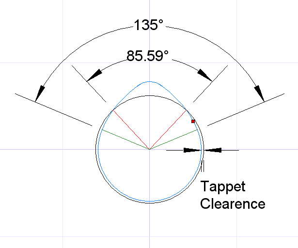 Introducing tappet clearance effectively places a gap between the cam-follower
and the cam. In the diagram here, the gap induced by the tappet clearance has
been exaggerated for clarity. Recall that in designing our cam, we specified
the opening angle so that the flanks would be tangential to the base circle
at the points defined by the cam opening angle, under the assumption that
the cam follower would faithfully and exactly follow the cam profile and
lift would commence at the desired points (the green lines).
Introducing tappet clearance effectively places a gap between the cam-follower
and the cam. In the diagram here, the gap induced by the tappet clearance has
been exaggerated for clarity. Recall that in designing our cam, we specified
the opening angle so that the flanks would be tangential to the base circle
at the points defined by the cam opening angle, under the assumption that
the cam follower would faithfully and exactly follow the cam profile and
lift would commence at the desired points (the green lines).
 .
.
Source Code for the Curious
This program is a PHP translation of an earlier Java language version written
as a command line utility for personal use.
To make it suitable for a wider community, the utility was "wrapped" in a
Java Applet. While this worked and was easy for me, the numbers were effectively
"painted" to the graphics display, not printed. This meant the data could not
be cut and pasted from the screen, and some browsers chopped off the bottom
of the page when printing.
![]()