 |
Westbury Whippet Project:
|
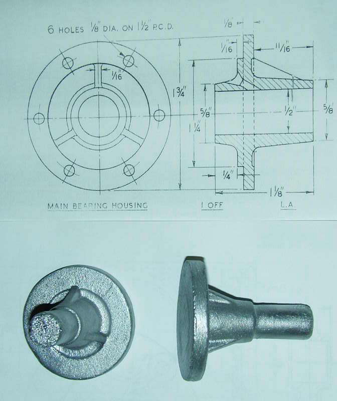
Logically, the next part to make would be the crankshaft. Following the established philosophy of making things that other things fit into first, we must begin by machining the front bearing housing and its bushings. At this point, the first serious problem with the Hemingway parts emerges: seems an over-zealous individual at the foundry has circumcised the nose casting! Maybe they thought they were being helpful in removing what they took to be a casting sprue, except it wasn't—it was an essential part of the casting. Notice that the rear of the casting is flat, while it should have a protrusion that supports the aft crankshaft bushing as seen on the plan underneath it.
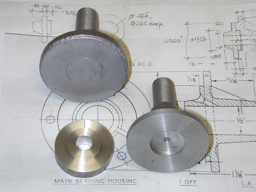 Hemingway were notified straight away, but not wanting to wait for a replacement, I decided to attempt a repair (they don't call me the Loctite Kid for nothing!) A new piece with a spigot can be glued into a hole bored into the casting. We can't make this too large in diameter, nor of any great length or the required hole will weaken the protrusion on the casting.
 Worse, when you think about it, this is the most heavily stressed part of the engine as it must take the force of combustion once every two revs, so the repair will need to be well supported. This can be accomplished by machining the insert so that it is fully supported by the opening in the crankcase into which the nose piece fits. The plan shows a 1/16" wide register, so we can extend this back to 1/8" so that it is composed of both casting and insert. In this way, the insert will be fully supported by the crankcase and combustion shocks will transfer direct to the case and hopefully not over-stress the glue joint. Rivets would be nice too, but there is little room for them.
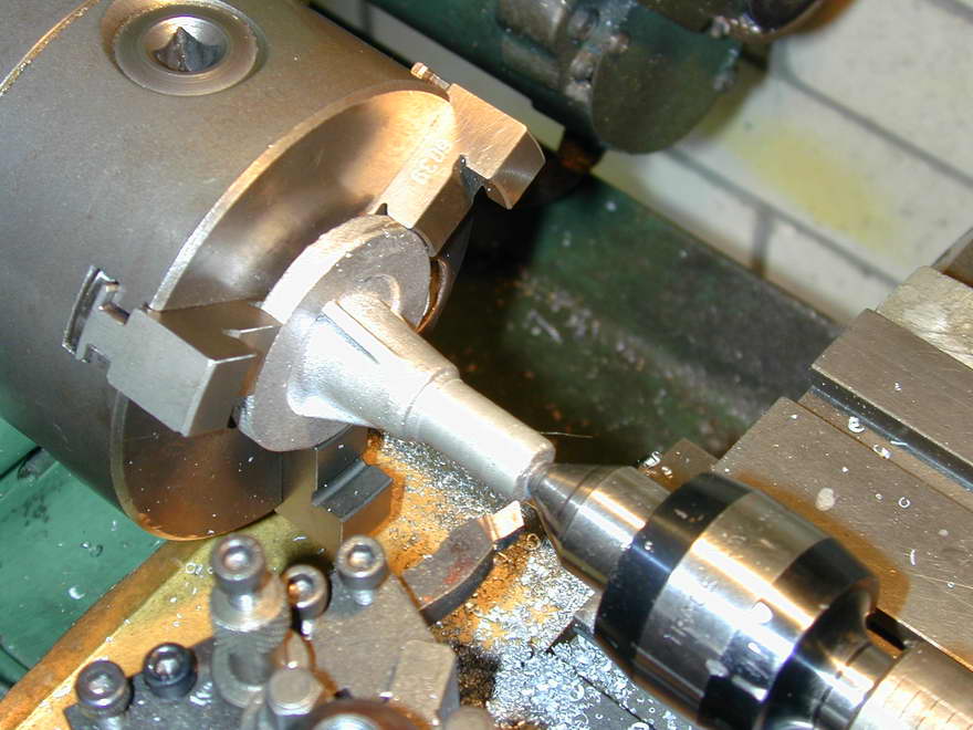 Preparation for the repair comprised gripping the casting on the rough flange so that the chucking piece could be trued up. This required the infrequently used "outside" jaws for the self-centering chuck, and a spot of tailstock support after the casting had been tapped about to get the point where the end would eventually be running kind of true. The part if then gripped on the chucking piece (duh) for facing and counterboring. The fixup is turned to a Loctite fit and glued in place as seen above.
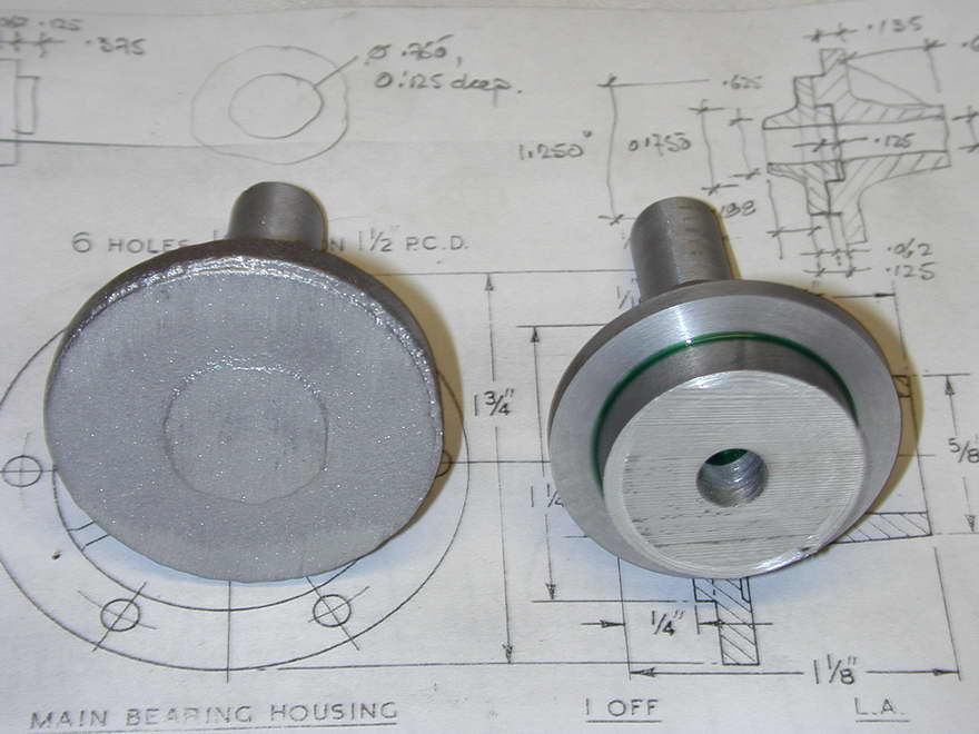
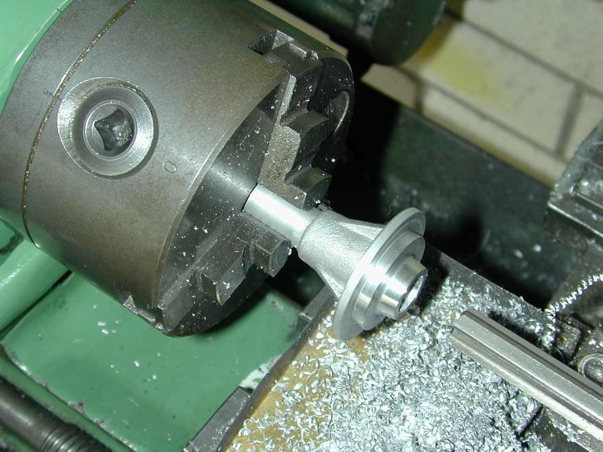 With accelerant, Loctite can attain 90% of ultimate strength in a hour. Without, you may get 80% a day later—consult the data sheets (available on line). So I did something else for a day, then machined the spigot, composed in equal parts of cast and inserted material, to a close fit in the crankcase. At the same setting, the nose was drilled and reamed for the bushings. The Flange OD was brought to final size and the front face rounded.
 |
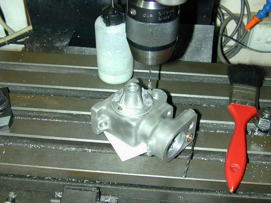 |
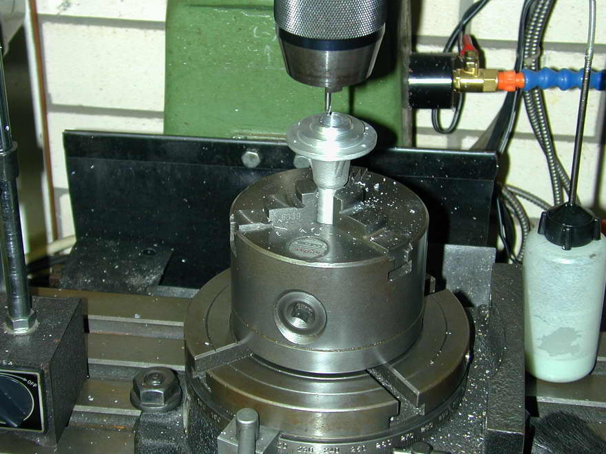
The last step is to drill the six attachment holes in the nose piece 6BA tapping size (#42), then spot one of these through into the crankcase. Tap it, open out the corresponding hole in the nose, and attach the casting with a single screw to spot the rest of the holes to be tapped. Be sure to mark the orientation of the nose casting on the rear face before opening out all the remaining holes to 6BA clear size. The plans say 1/8", but I think a 0.125" diameter home is a bit generous for a 0.110" diameter screw. I drilled #32 to give a bit of alignment latitude.
The bushings are turned from supplied bronze rod and are straightforward drilling and reaming jobs. I should not have to say that they are best drilled and reamered (as the Brits would say) at the same setup to ensure concentricity. This requires a chucking reamer as the hole will be blind. I prefer to make them a glue-in fit rather than a force-fit as the latter generally closes up the bushing by a few tenths, complicating fitting the shaft if both bushings do not close up by the same amount. Only thing to take account of is the protruding length of the inner bush. This must be adjusted so that the space between it and the rear, follower shaft bush will neatly accomodate the assembled shafts with minimal end-play—say 10 to 15 thou.
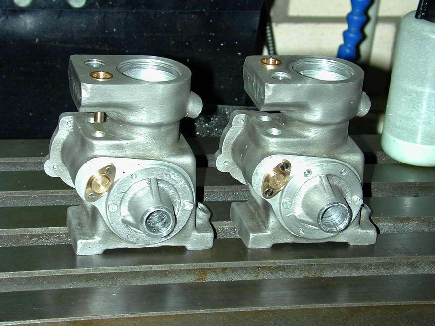 I have to say that the cast alloy on my kits was simply awful to machine and ream, unless absolutely flooded with coolant/lubricant (I use a blue tinted stuff called Kool-Tool, or something like that). But short of pumping, which I'm not equipped for, it is hard to get the coolant all the way up the bore to be reamed, so galling and scraping still occurred in the bore resulting in the hole as viewed here appearing decidedly second-hand. Hemingway have been appraised of this and are looking into it with their foundry. I take some consolation that the gouges and groves provide more surface area for the Loctite that will hold the bushings in place.

|
This work is licensed under a
Creative Commons Attribution-Noncommercial-Share Alike 3.0 License. |