 |
Westbury Whippet Project: Page 2Click on a photo to view it larger size. |
This page details making the camshaft and all the associated bits that make it turn. The order for making the parts, shown below, was chosen so that bearings where available when shafts were being turned to fit them. Some parts need to be put aside, part finished, until another is ready.
- Cam Bearings
- Camshaft
- Cam Gear and Nut
- Gearcase Cover
- Follower Shaft Bush
- Follower Shaft
- Driver and Idler Gears
- Idler Shaft
Camshaft Bearings
 |
 |
 |
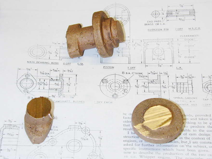
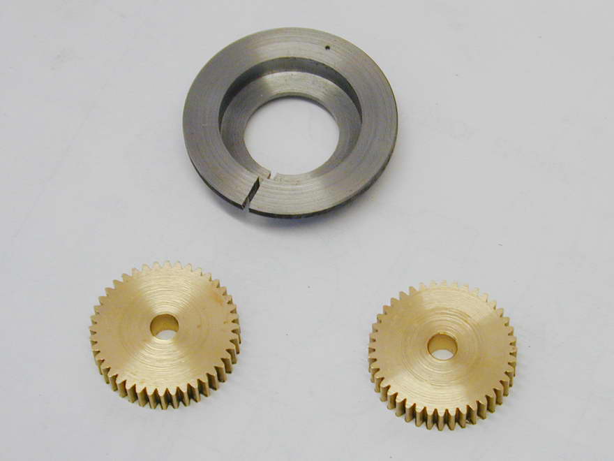
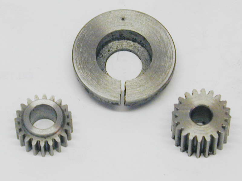
The cam bushes are provided as a one-piece gun metal casting. This needs to be sawn in two as shown above. Depending on registration of the split pattern used to make the casting, a little jiggling may be needed when chucking the part to ensure the finished bit falls within the cast shape. A four-jaw chuck is needed for the front bearing. The rear can be held in the self-centering chuck. Gun metal blunts HSS tooling fast! Be prepared to resharpen during the job, or you may have problems as I'll describe soon. The front bearing requires a 5/16" "chucking reamer" to finish the blind hole. If you only have a hand reamer, drill and ream it through, then fit a plug to the front.
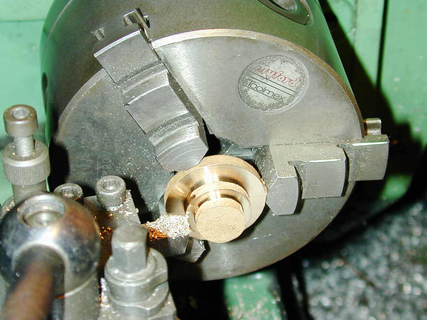 After turning the rear bushing to fit the crankcase and reaming it through, it is reversed and faced back to 1/16" thick. Caution! Unless your tooking is sharp, the facing operation will raise enough heat to cause the flange to warp as it get thin, going convex towards the tool. So you'll think it is 1/16" thick when in fact, it is less due to the distortion.
After finishing, the bushes are drilled for the attaching screws at 8BA tap size (#49) so the holed can be spotted through onto the crankcase for tapping. The holes can then be opened out and countersunk. Each bush has a lubrication hole that can be drilled with a #0 center drill, opened out to 1/16". Be careful feeding in the drill on angled oil holes as the tip will break out into the bore on one side first—a sure recipe for a broken drill unless you are taking it slow.
Camshaft
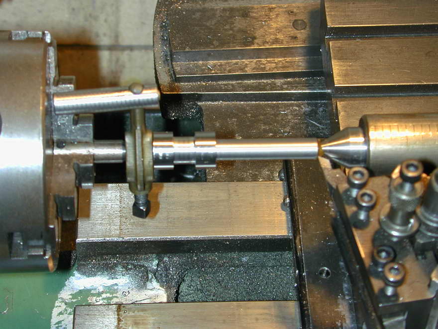
The camshaft is turned from a piece of drill rod that will be left "soft" due to the danger of it warping if hardened. It has multiple sections of different diameters that must be perfectly concentric, or you'll be in trouble with friction and binding. The only way to ensure this is the turn between centers. This also allows the part to be removed for testing in the bushes, then replaced for further machining with no loss of concentricity.
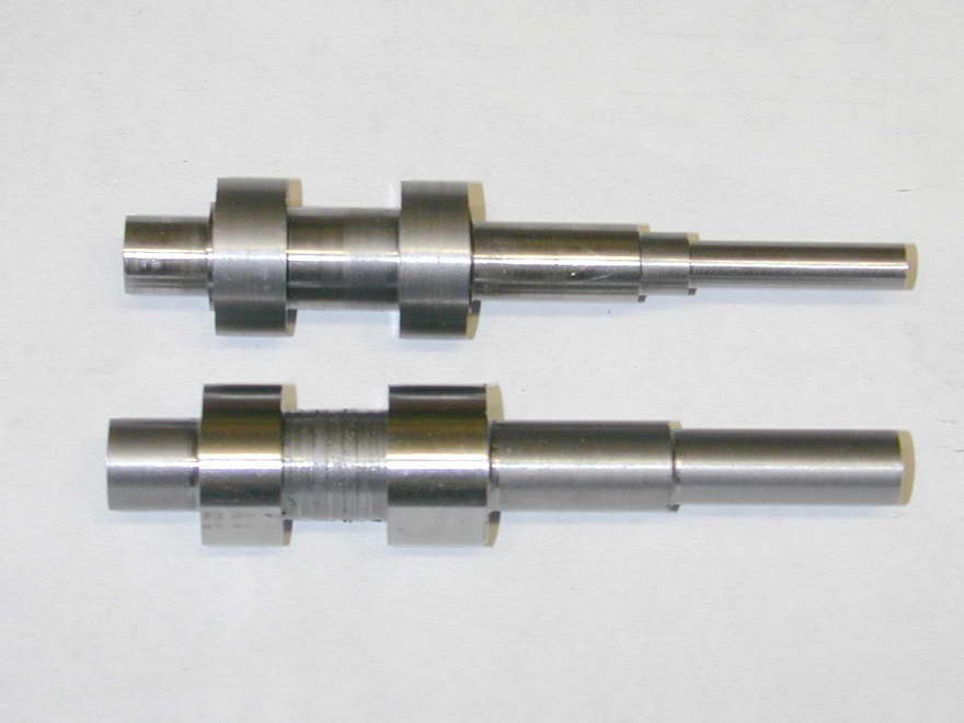 In this photo, one shaft is has been roughed to shape and the other finished and polished to a running fit in the three bushes pictured earlier. The polishing is done with a piece of heavily oiled 600 grit wet 'n dry paper backed with a steel rule while the part is spun at high speed.
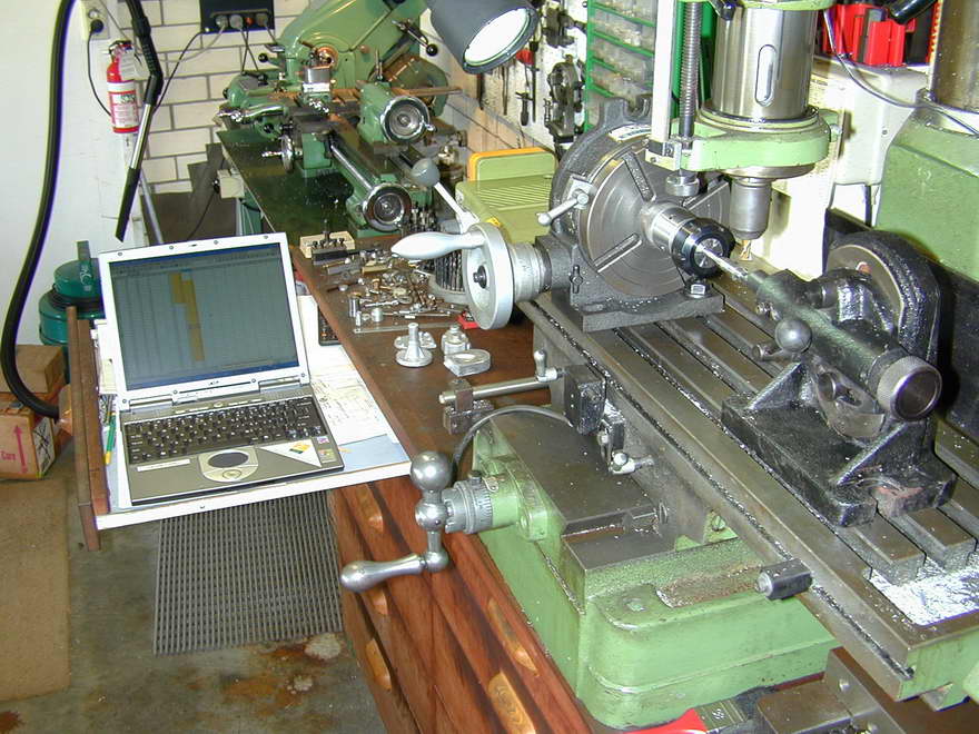 Here is the setup for milling the cams. The laptop is displaying the lift table for both cams as generated by CamCalc. I've chosen 5° as the rotational increments and adjusted the data to undercut the base circle by the specified tappet clearence of 0.005". The generated data for the exhaust and inlet profiles has been assembled into a single spreadsheet so that the maximum lift for the two is separated by 110°. Quite a lot of milling will be done at this depth of cut (0.099" — 0.094" lift plus the 0.005" undercut) so the entries where mill quill adjustments must be made have been highlighted.
 Start by setting the rotary table to zero and lowering the quill until the cutter just kisses the cam blank. Zero the quill readout and we are ready to cut. The data table has been arranged so that the maximum lift of the inlet cam is at zero degrees. The numbers of the spreadsheet correspond to table rotation and will hopefully produce a cam timed for normal counter-clockwise operation. Now wind the cutter out from the blank, move the spreadsheet cursor to the 5° cell, set the downfeed to the depth for that location, then wind the mill Y axis in and out, taking a miniscule cut. Repeat 71 more times. This photo shows the finished inlet cam at the point where we have just finished the last cut. Note the smooth looking nose radius. Light filing and polishing is still required, but that is still required for the ETW/Chaddock jig method. Short of a cam grinder, we can do no better.
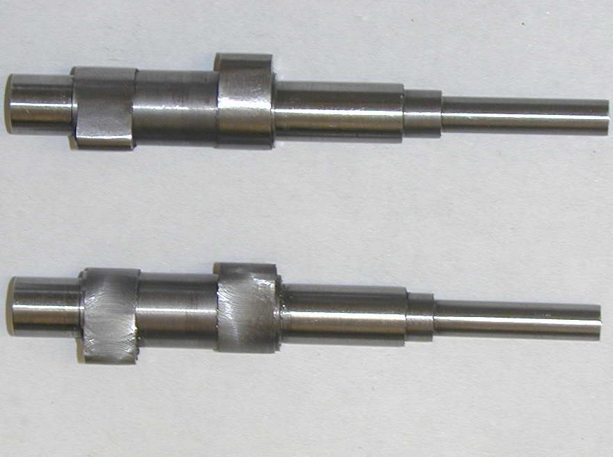 The procedure for the exhaust cam is the same, making sure to move the cursor to the correct data column first (this cam has 10° more open period and a larger nose radius). The photo shows a before and after shot with the top shaft filed and polished. The other looks quite rough in comparison, although the photo makes this appear much "worse" than reality for some reason. No cutting fluid was used during machining. It may improve the "raw" finish, but would require a delivery pump and I'd probably end up with more in the laptop than on the job.
Cam Gear and Nut
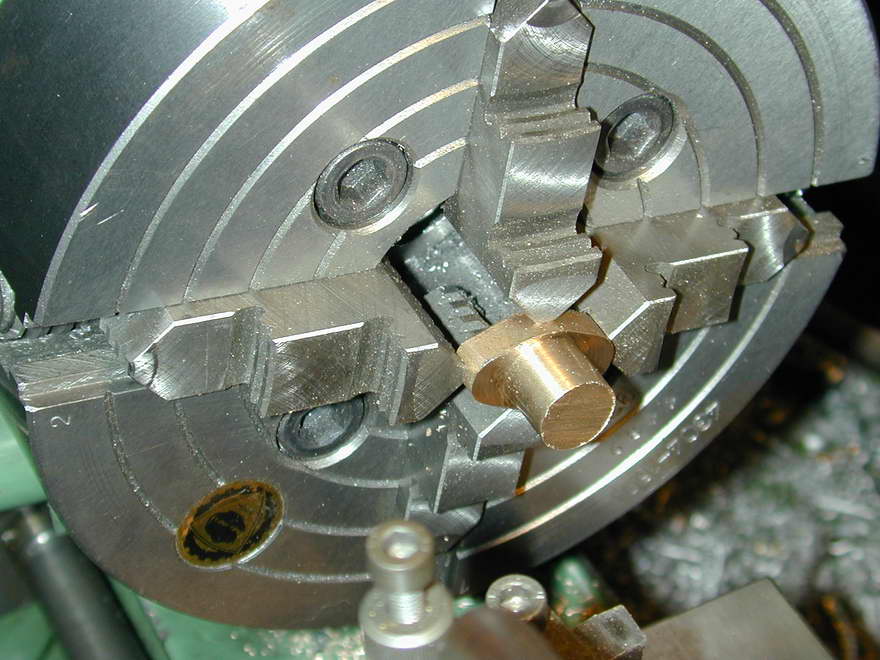
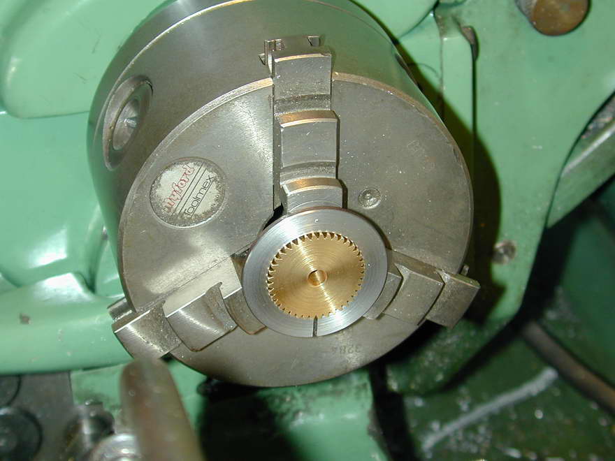
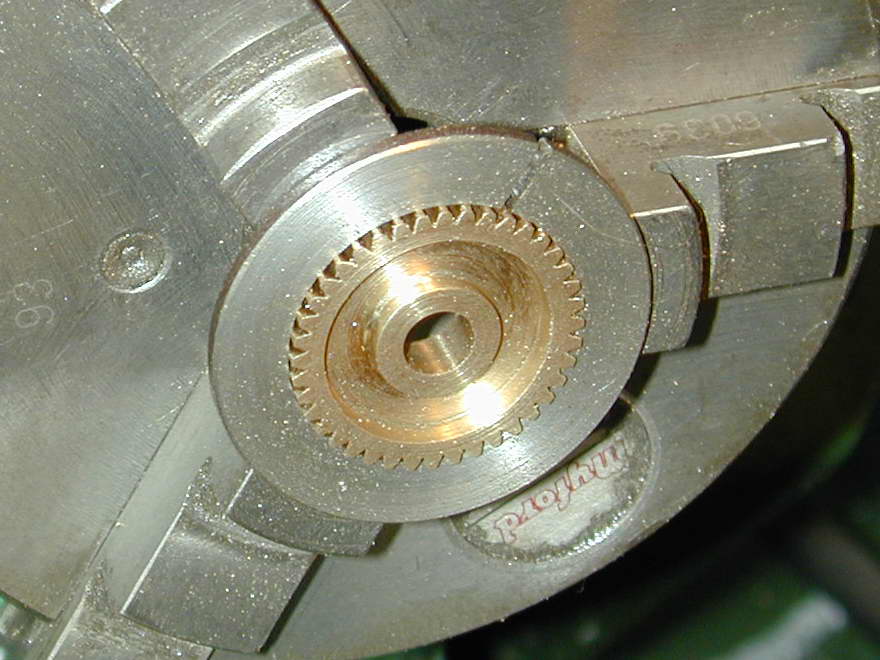
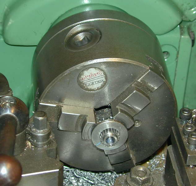
 Before the thread can be cut on the camshaft, the taper must be cut. And before that can be done, the cam gear must be prepared so the same topslide set-over can be used for both. The pot-chuck shown here will hold the gear in the correct alignment for this operation (note the center-pop mark at the position of the #1 chuck jaw point, marked when the fitting was made). The supplied gears have pronounced burrs. Be sure to measure the diameter for the pot-chuck across the middle of the teeth, but the burred edges. An you'll need to hit each tooth with a fine file to remove the burr before the gear will fit in the chuck. across can be turned
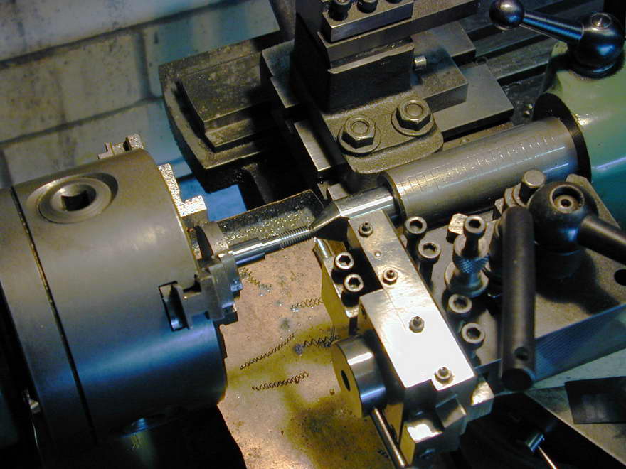
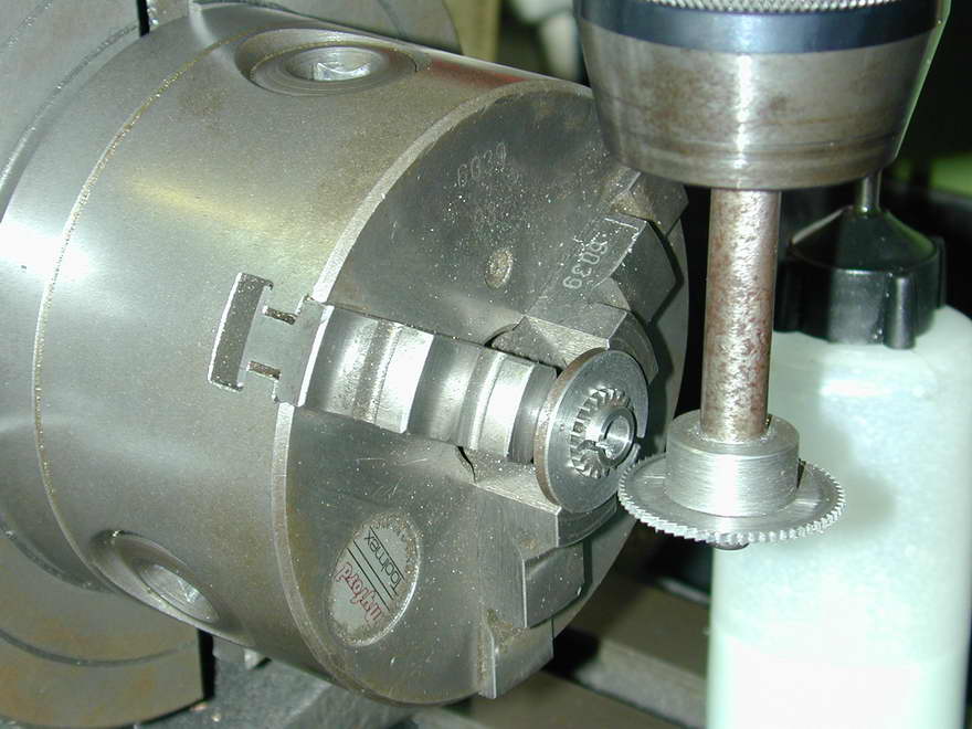
 Now that the pot-chuck is ready for use, the top-slide can be set over to about 5° and the taper cut on the cam shaft, for which it needs to go back between centers. The dead center which is just a length of 1/2" steel stock, is re-trued to 60° to ensure it is on the lathe axis and assure concentric alignment of the shaft. The taper is turned to a light mark made on the shaft that will make the shoulder just proud of the bearing end.
 The last operation can now be made on the shaft which is to cut a 40TPI thread for the nut which will lock the cam gear onto the taper. This could be cut with just a tailstock die holder, but I like to partially screw-cut the thread to provide a positive start for the die first. The nut, which is only 1/8" thick, can be made later. It will not be described as this is a simple operation. But before upsetting the top-slide, mount up the gear to turn a matching taper to the shaft.
 The supplied gears have a bore of 3/16" that must be opened out to 1/4", then taper turned to 10° included angle. In this shot, the gear has been drilled, reamed, taper turned, faced, reversed in the chuck, faced again, and an unnecessary but attractive recess rebated into the face. After removal, the burrs on the edges of the teeth must be cleaned up with a small, triangular jewellers' file.
Gearcase Cover
 Gearcase 1 |
 Gearcase 2 |
 Gearcase 3 |
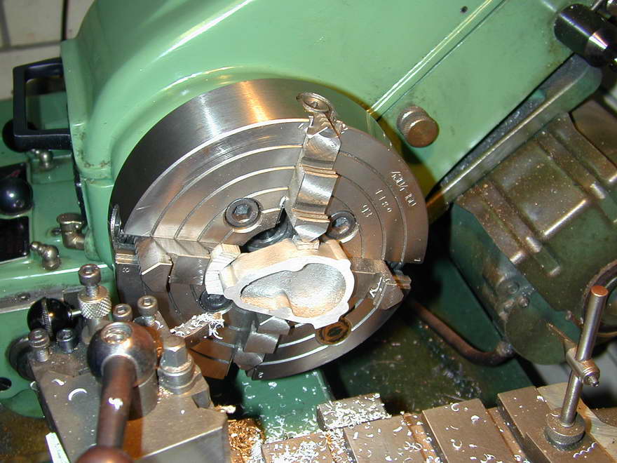
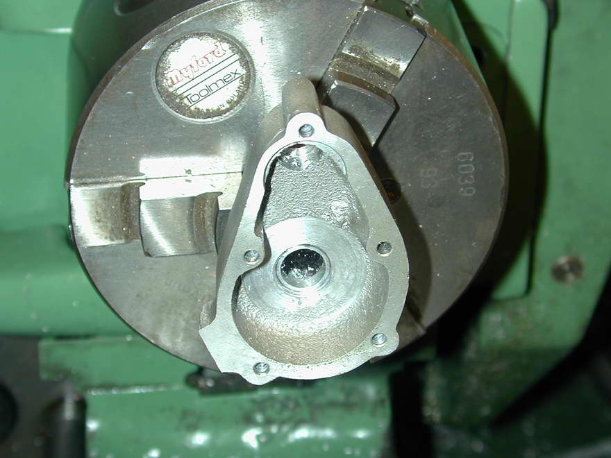
The first step on the gearcase cover is to face it back to the required internal depth. This is a four-jaw chuck job. The finish should be as good as you can achieve if gasket-less assembly and no oil leaks are the aim (photo 1). Next (photo 2), the crankcase can be gripped on the front opening in the three-jaw chuck to jiggle the cover around and get the best compromise for the follower shaft bore center between centering in the boss, and having the cover mate up with the cast flange on the crankcase (which is not even vaguely correct in profile). This done, the bore for the follower can be drilled 5/16" for the nut that holds the driver gear to the follower shaft. This runs in the unbushed case, so we have a couple of thou running clearance that can be turned into the nut later.
 The cover is now wrung onto a 5/16" mandrel so that a recess can be counterbored, concentric with the follow shaft hole, which fits over the register left around the follower bush hole on the rear of the crankcase. Even though this recess is open on one side, it will serve well enough to locate the gearcase on the main casting.
 Gearcase 4 |
 Gearcase 5 |
The holes for the gearcase cover screws can now be drilled through spotting them into the center of the cast bosses. The plans say drill 1/8", rather generous for 6BA screws. I drilled #42 which is the tapping drill size. They can be opened out #33 after spotting into the crankcase (photo 4). With the gearcase in clamped in position, two opposing holes can be drilled through tapping size using the gearcase cover holes as guides. After tapping and opening out the corresponding holes in the cover, it can be securely attached to spot, drill, and tap the remaining holes (photo 5).
 Gearcase 6 |
 Gearcase 7 |
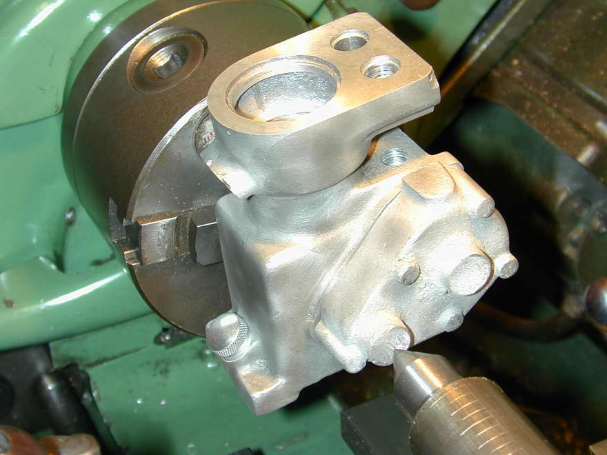
The crankcase is now remounted on the faceplate and the camshaft bore clocked to run absolutely true (photo 6). The cover is now attached with all its screws and the hole for the cam bush bored to a Locktite fit on the bush (a straight boring and reaming job in bronze, not illustrated). The protruding boss can be faced back and turned concentric with the bushing hole at the same setting, just for cosmetic reasons (photo 7). The bush protrudes from the cover and forms the clamping boss for the timer assembly. You can partially see in photo 7 how well (badly) the cover matches the crankcase profile. This will get some attention later and a touch-up with the sand-blaster.
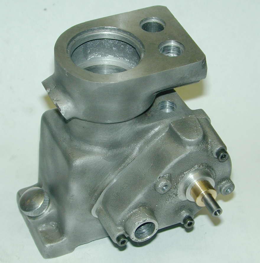 The big test of this operation is to insert the camshaft and assemble the cover with the rear camshaft bush in place. If sufficient care has been taken, the shaft will turn freely, and it does! You can see how it would have been easier if the gearcase cover had been fitted before boring the camshaft tunnel in the crankcase. The location for the bore could have been marked on the cover and the assembly centered on the faceplate. After reaming the cover for the bush, the cover could be removed and the case drilled, reamed and bored, assuring concentricity. But all's well that ends well, even if I did cause myself some extra work.
 The gearcase must now be bored internally to provide clearance for the big timing gear and a recess for the flange of the bronze bush. For this operation, it is again wrong onto the 5/16" stub mandrel used earlier. The interior of the cover has a number of areas where the sand had fallen away, producing "lumps" that had to be turned away, but eventually the camshaft with gear attached rotated freely.
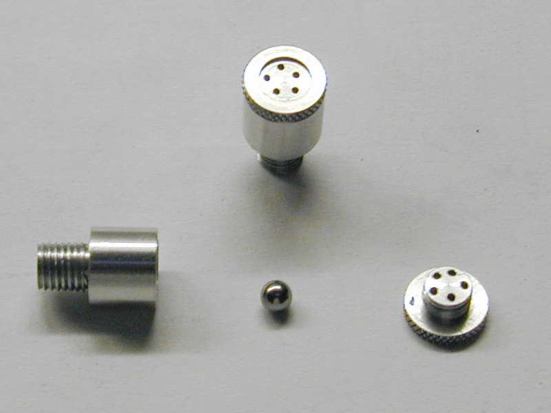 The platform on top of the gearcase cover is intended as the mounting face for a crankcase breather. The plans do not show this part, but the ETW text suggests that fitting a ball-check valve is not a bad idea as this will allow the case to vent while maintaining a slight negative pressure which will help prevent oil leaks. I faced the platform, then drilled and tapped 1/4" 32TPI (glowplug thread) for the vent. The plans give no details of this valve, so I've adapted the design shown on ETW Kinglet side-valve engine. A 5/32" ball sits in a center drilled cone, free floating in a 3/16" cavity, retained by a screw-in cap (the Kinglet design used a cross-bar). The design could be a lot better, but as the engine is unlikely to be subject to negative-G, or a lot of acceleration, it should serve.
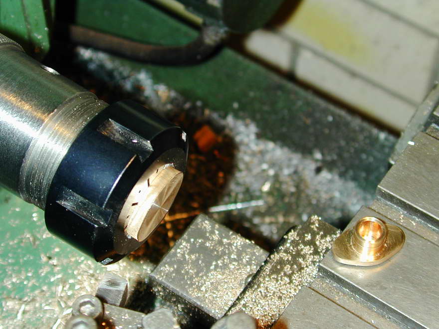
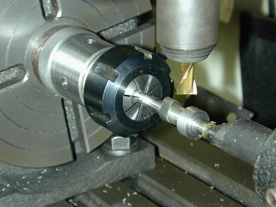
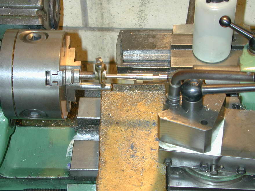
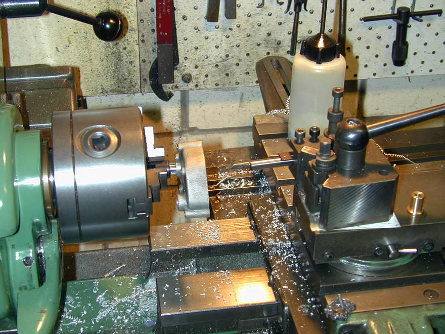
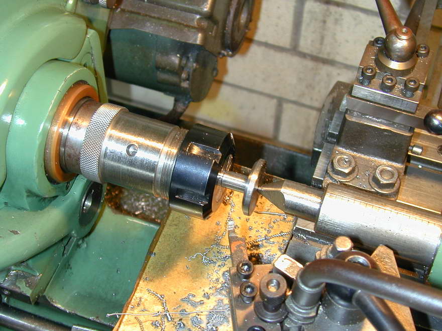
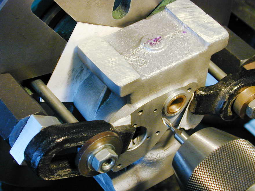
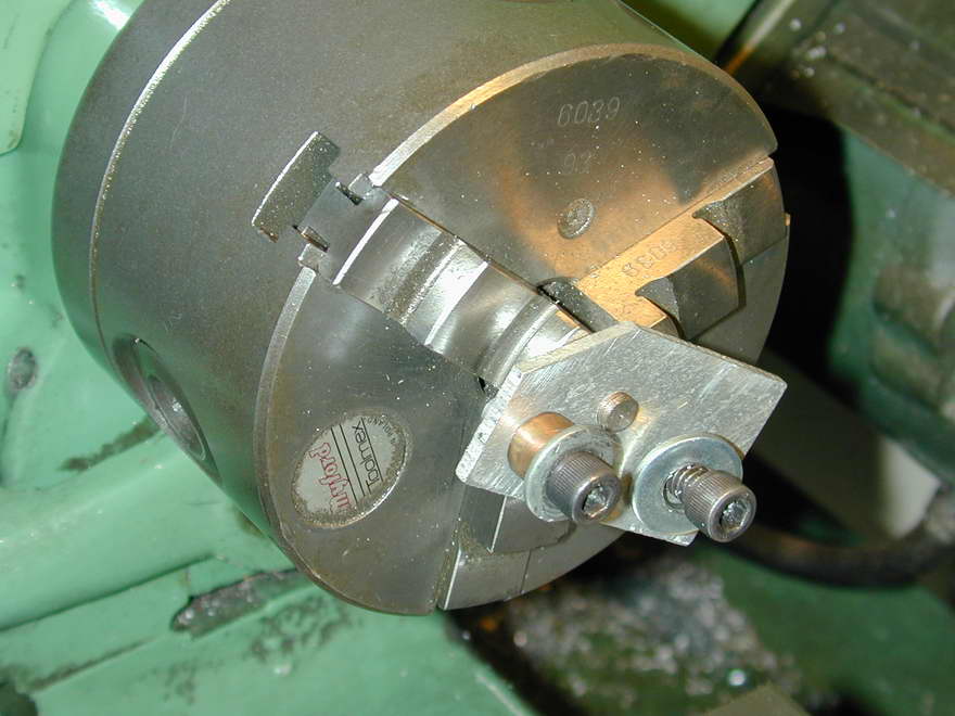
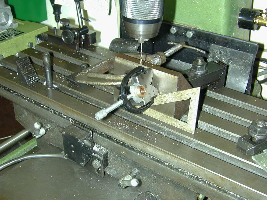 Following our philosophy of making things that fit into holes made previously, the bush for the follower shaft is turned to be a close fit in the crankcase. The reamed hole in the bush will be a guide to the diameter of the actual follower shaft itself. The bush is simple turning and reaming, but the setup I used to drill the oil passage is worth documenting, and that is what you are looking at here. As usual, especially when drilling brass or bronze which are "greedy" metals, take care when breaking thru into the bore at an angle or you'll break a drill—like I did, even knowing of the danger in advance! Luckily, it could be pushed through and the EDM did not have to emerge from under the bench.
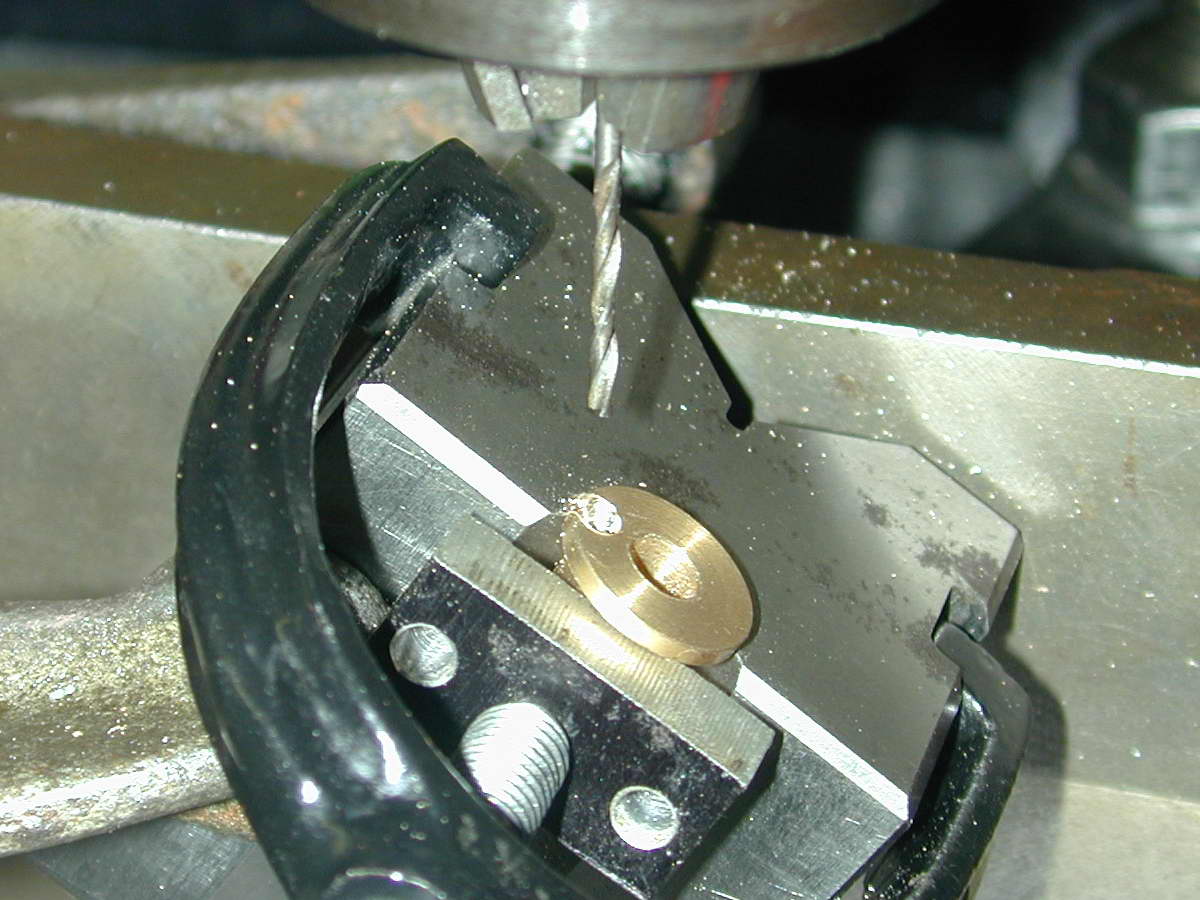
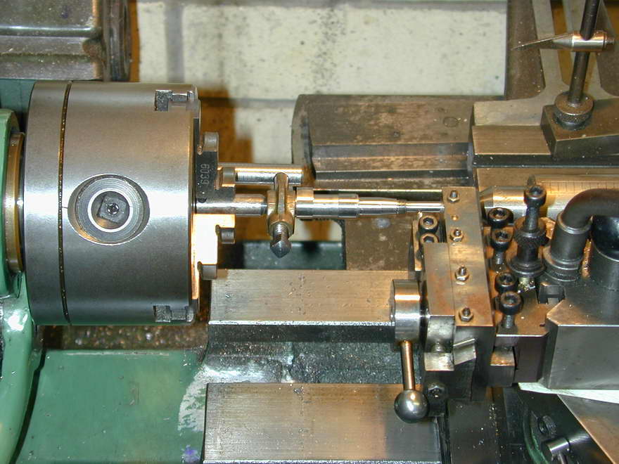
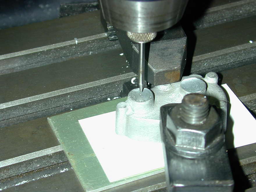
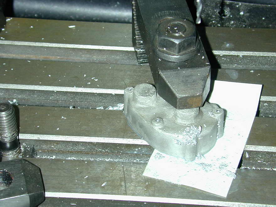
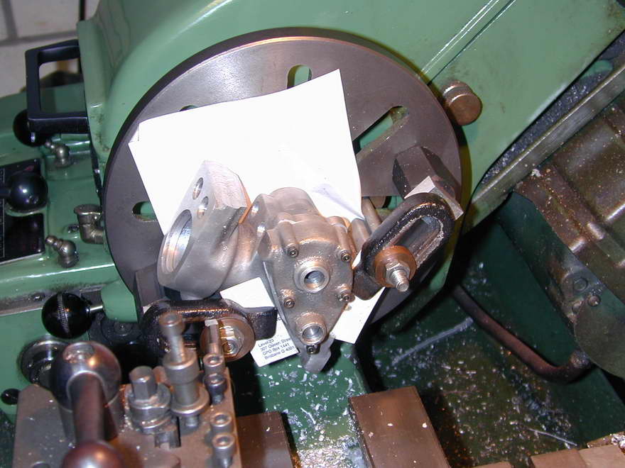
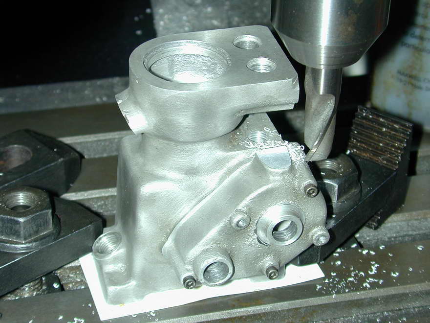
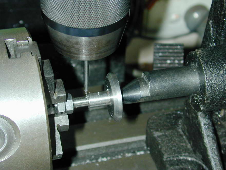
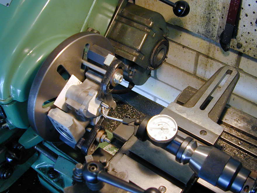
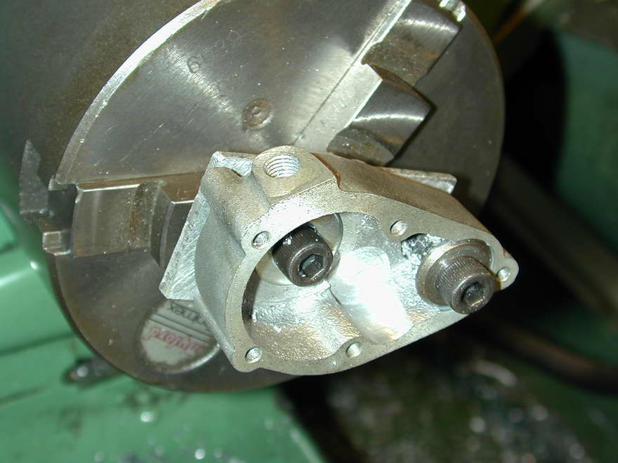
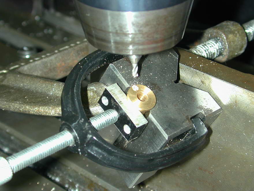 The lubrication hole in the gearcase cover cam bush is drilled in a similar way, but is complicated by the impossible angle at which the drill must enter the flange. This photo shows a rigid, 3/32" stub end-mill being used mill a slight pocket that will provide a start for the center drill, which in turn provides the start for the twist drill. Clamping everything rigidly helps too.
Follower Shaft
 Follower 1 |
 Follower 2 |
 Follower 3 |
The follower shaft is a straight piece of turning, complicated only by the good, tough steel provided in the Hemingway materials kit (EN16T). Sharp tooling and slow speed will produce an excellent finish that can be polished with fine glass paper backed by a steel rule and a lot of oil. Arrange the final cut to be three to five thou deep as smaller cuts may give a disappointing finish (photo 1). I like to screw-cut threads 1/4" in diameter and up, using a die only to finish the thread form. This ensures the thread is true and requires a lot less force when running the die up the almost finished thread, resulting is less wear on the die and less clamping force needed on the part being threaded. Photo 2 shows a GH Thomas retracting tool holder (made from a Hemingway materials kit) roughing out the thread. In photo 3, the shaft has been reversed and held in a collet to finish the web and drill the central oil passage. Collets grip tighter and need no protective shim as they grip equally over the whole surface.
 Follower 4 |
 Follower 5 |
Photo 4 shows the shaft transferred to the mill to drill 1/16" holes for the oil passage that intersects the hole drilled up center of the main journal, and another drilled half way through the 1/4" section at the shoulder to take the drive pin for the pinion. This engages with a slot which will be cut into one side of the boss of the drive pinion. The pin is glued in, although clamping forces would probably provide adequate retention pressure. Photo 5 shows the nut which presses the pinion home ready for parting off. The hex portion will ride outside the gearcase cover while the shank runs in the cover itself. The nut is turned to a running, but not bearing-quality fit in the cover hole, so a square section, right-hand, 10 TPI thread is cut in the shank to screw the oil back into the case (assuming "normal" engine rotation).
Driver and Idler Gears
 The follower shaft and intermediate gears need a similar treatment in another pot-chuck: drill 15/64", ream 1/4", face to size and turn back the teeth to form 1/16" boss—or so the plans say. In my humble opinion, the height of the boss on the follower gear is right, but that in the idler either needs a 1/8", or a 1/16" thick washer placed under it on the shaft, otherwise it is not going to mesh at the same level as the others. We'll come back to this later. Like the brass timing gear, the supplied steel gears have a lot of burrs that must be filed away to obtain the correct mesh. This is normal for commercial gears that are "made by the mile and cut off my the yard".
 The driven pinion gear needs to have a 1/16" wide slot cut in one side of the boss the engage with the drive pin in the follower shaft. This requires a rather small diameter slitting saw. It could be cut through both sides, but then we'd be able to assemble the thing in two ways, and so open the door to the possibility altering the timing if assembled 180° to where it has been timed correctly.
Idler Shaft
 Now the idler pinion can be fitted. As suggested by the ETW notes, this is done using a "toolmaker's button" to get the position for correct mesh right. The "button" in this case is a piece of 1/4" drill rod, drilled through 5/32", faced and parted off to ensure the ends are square to the axis. The button and idler are used to get the gears turning freely, holding the shaft with a finger. the position of a hole for an 8BA (2-56) screw is then spotted through the button. This allows the button position to be jiggled around a bit so that a precise mesh of the gears for full engagement and free running can be obtained. The screw is then tightened down. Obviously, the screw needs a washer under the head. Equally obvious—I hope—the washer needs to be small enough that the gear can be removed after the screw is tightened up.
 With all the gears removed, we now mount up the crankcase on the faceplate, clocking the button to run perfectly true. I'm using a "co-axial" DTI for this, but a plunger type DTI would have done the job just as well. The co-axial one was chosen because it is more sensitive than any of my plunger type ones.
 The button can now be removed and stored in that drawer of funny, carefully made little bits, the purpose of which has been completely forgotten for all time. The actual idler pin screws into the case with a 3/16" 40 TPI thread (a "Model Engineer" series thread), so a 5/52" slot drill is used to drill out the 2-56 tapped hole. Slot-drills are much more rigid than twist drills, so there is less chance of the threaded hole drawing the tool off-axis.
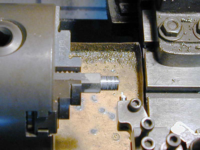
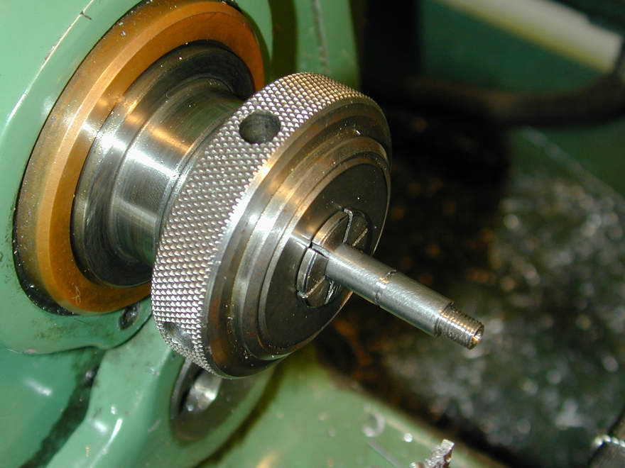
 This photo shows the final result. The 5/32" hole has been counter-bored a short distance to allow for the impossibility of running the 3/16" 40 TPI die right up to the shoulder of the 1/4" outside diameter idler shaft with a standard button die. This ensures that the shoulder will butt up to the case, keeping the idler shaft perpendicular.
 The idler shaft itself is formed from 1/4" mild steel. This material takes a better thread than could be obtained in drill rod, but the surface will need case-hardening. As the shaft is short, there is no danger of it warping in the process. A recess is cut for a circlip that will retain the idler pinion. The shaft is also drilled and cross-drilled to provide oil to the pinion from the mist inside the crankcase.
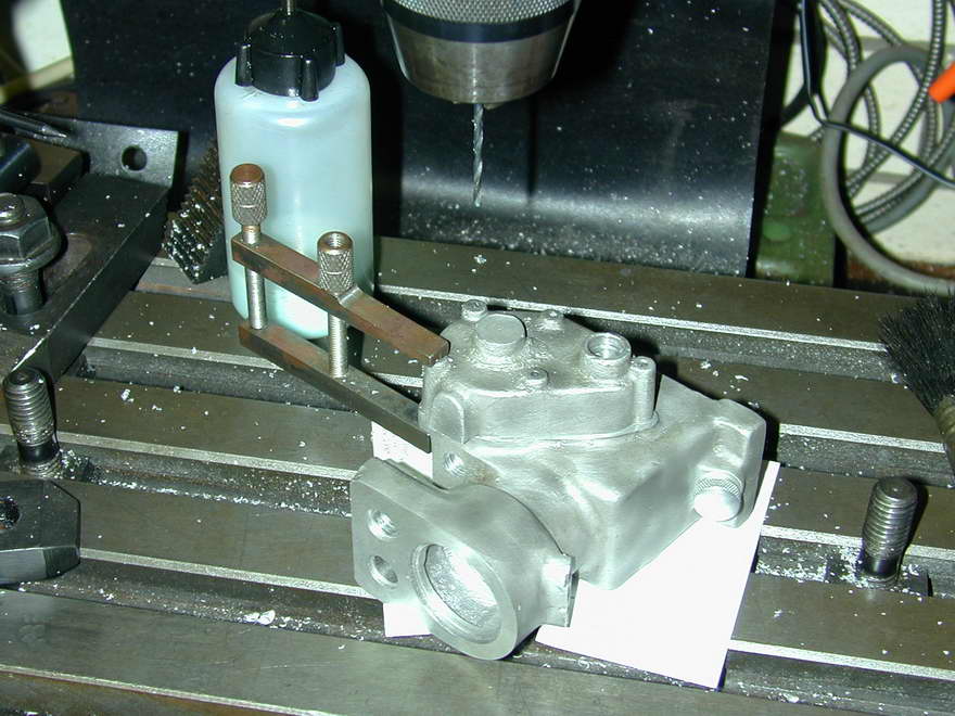
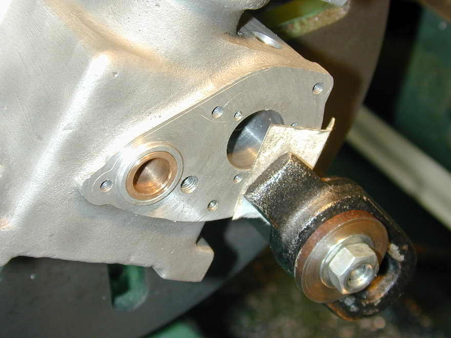
 Nearly done now. The last operation on the gearcase cover is to turn clearance for the idler on the inside of the casting. For this, a fixture is made that can be chucked on the axis of the idler and has tapped holes for screws that pass through the two openings in the casting allowing it to be jiggled about so that the right place for the counterbore can be determined by a bit of trial and error.
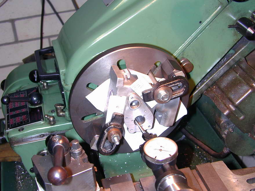
 Here we see the counterbore being formed. It comes rather close to one of the gearcase cover mounting bosses, but is far enough away to pose no problem, nor even embarrassment if the cover is removed while others are looking.
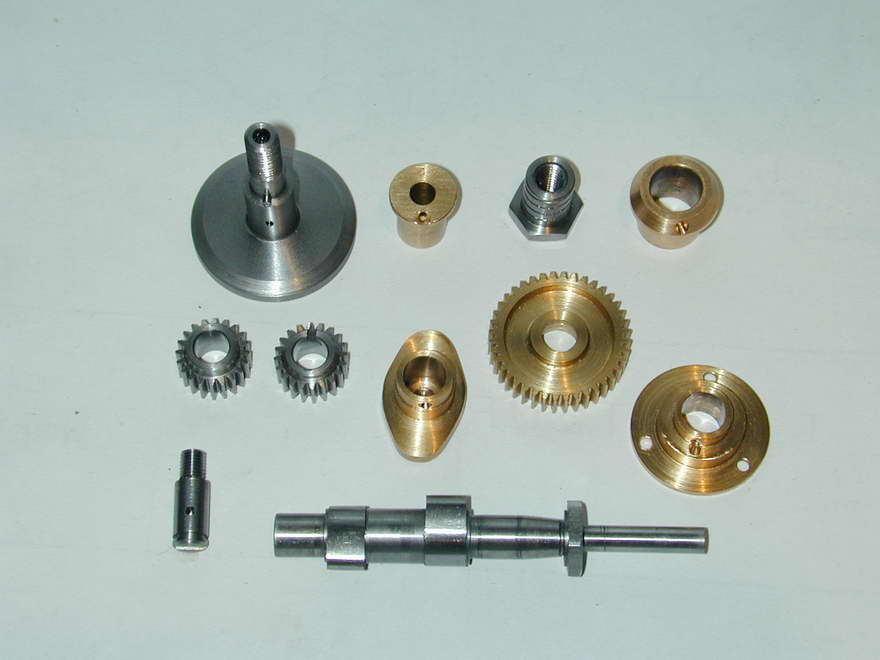
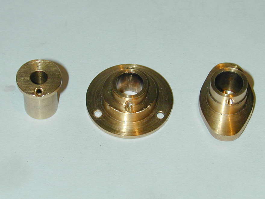
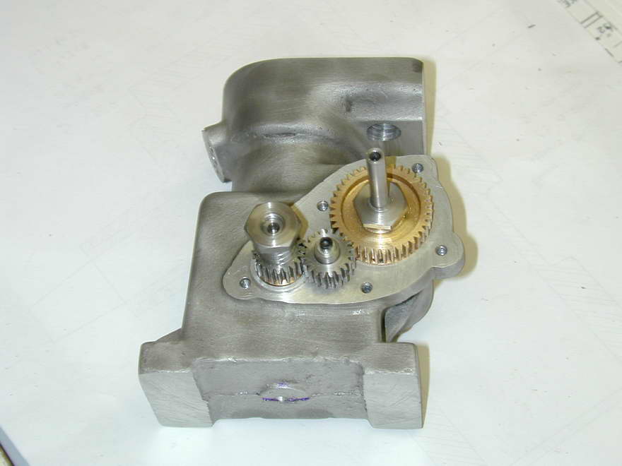
Well, that was a lot of photos and a lot more words than I'd intended to inflict on the world. The picture here shows all the shafts and bushed made in order to get the camshaft to rotate from the crankshaft follower shaft. The latter still requires the counter-balance cut-outs to be made and a driver slot, or hole, to be drilled to take the crankshaft driving pin. Those can wait until the crankpin is being turned. The front camshaft bush (the oval gizmo) also requires mounting holes. These will be added after the front bearing is in place as I can't decide yet what the orientation of the holes—which do not appear on the plans—should be. The bush flange is very, very close to the front opening, so some head scratching will be required.
The next logical place to attack is the nose-piece, bushes, flywheel and crankshaft, in that order. With those done, the follower can be finished and we can look forward to hours of mindless fun spinning the flywheel and watching the gears go 'round.

|
This work is licensed under a
Creative Commons Attribution-Noncommercial-Share Alike 3.0 License. |