 |
Westbury Whippet Project:
|
More things to fit in other things. We'll make the liner to be a drop-in fit into the bore in the crankcase, allowing it to be honed to finish before insertion. Final assembly will use high temperature Loctite to ensure the water jacket does not leak into the crankcase sump. The piston will then be turned to suite the measured bore.
Cylinder Liner
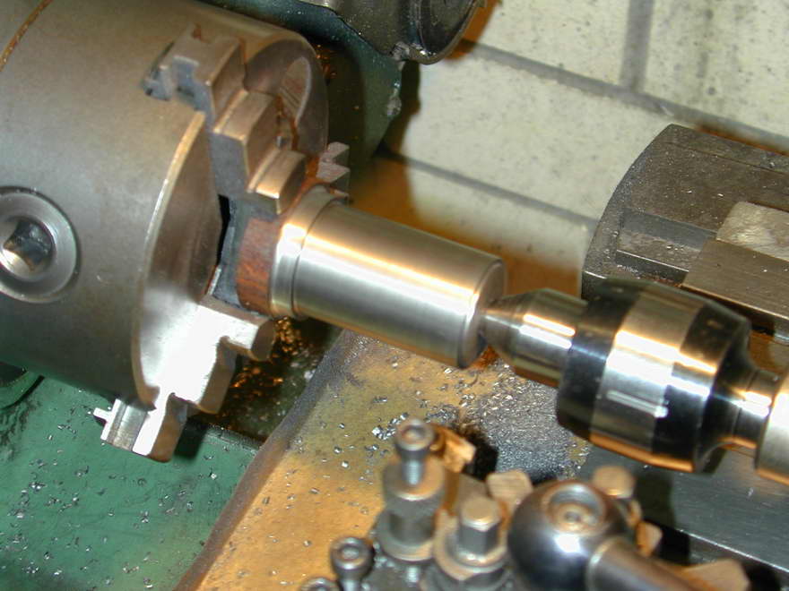 This is almost too simple to be worth describing. The supplied cast iron rod blank was only just long enough for use—I would have liked another 1/4 inch for chucking, but managed to work around that. In this blurred shot, the OD and the top lip have been finished to about 1.5 thou undersize, making it a slip but not sloppy fit in the crankcase. This also provides the required gap for the Loctite compound it will later be fixed with.
 |
 |
 |
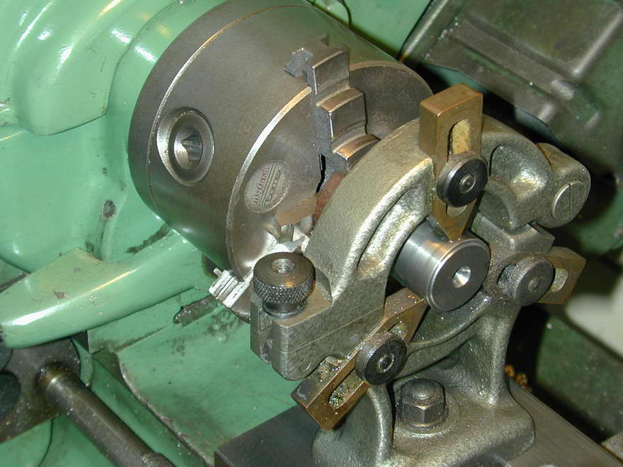
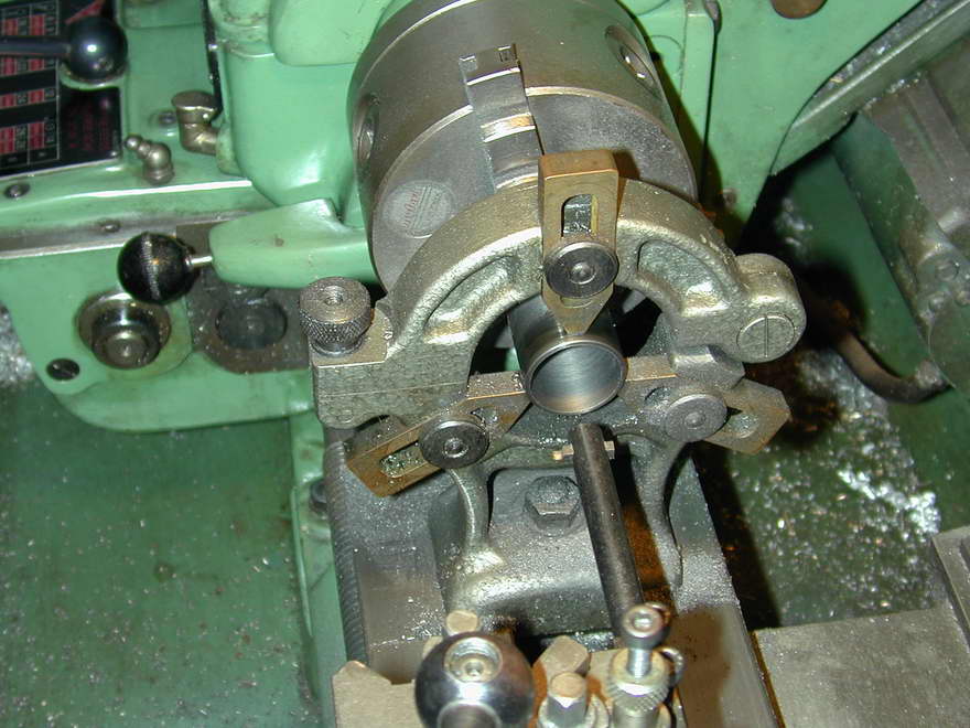
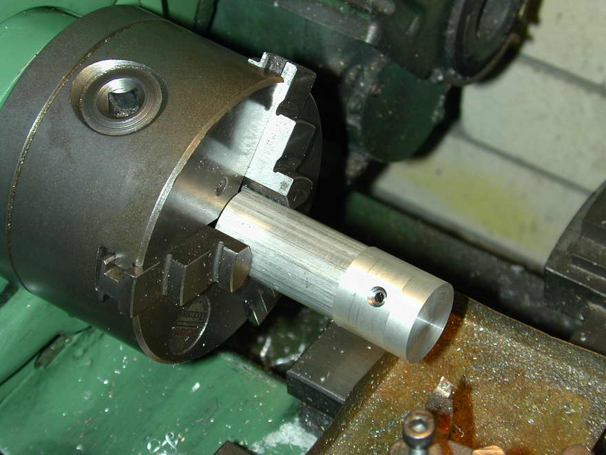
To bore the liner, the fixed steady is adjusted with the tailstock live center in place. The latter is then removed and drilling can start. The first drill used is 1/4" which opens the tip path for a 1/2" bit. The hole is then opened up progressively in 1/8" steps to 7/8", finishing with 15/16" leaving about 30 thou to be removed by a long, rigid boring bar. Lots of mess is produced as 90% of the bar is reduced to dust.
 |
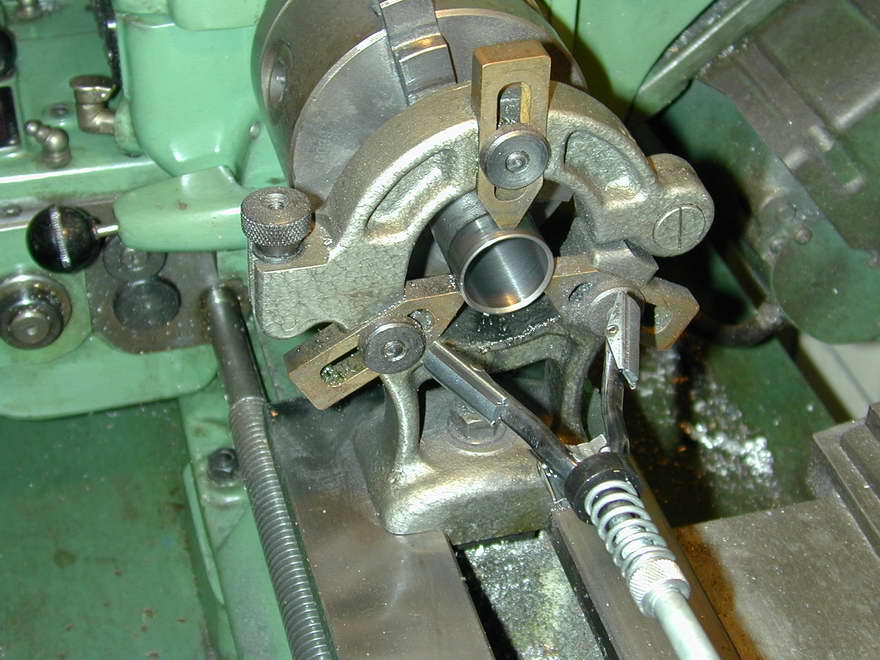 |
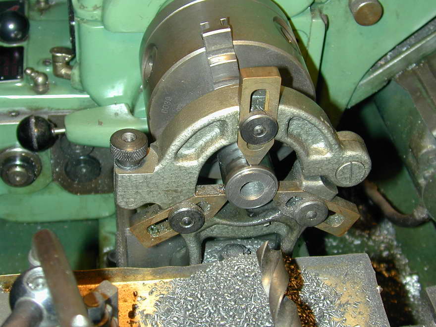
For CI, I leave about 0.0005" for honing, or a bit more if I don't like the finish the tool is leaving. The reason to minimize this is the danger of bell-mouthing the job when a lot needs to be honed away. In this case, that is not a great problem as a bit of bell mouthing at the bottom actually helps reduce friction where a close fit is not really needed, and any bell-mouthing at the top will be removed when the liner is parted from the chucking stub. Honing is performed with a el-cheapo auto-parts store brake cylinder honing tool, lots of oil, and high speed to ensure the mess is flung it all over the place. At least it gets my helpful cat out of the workshop.
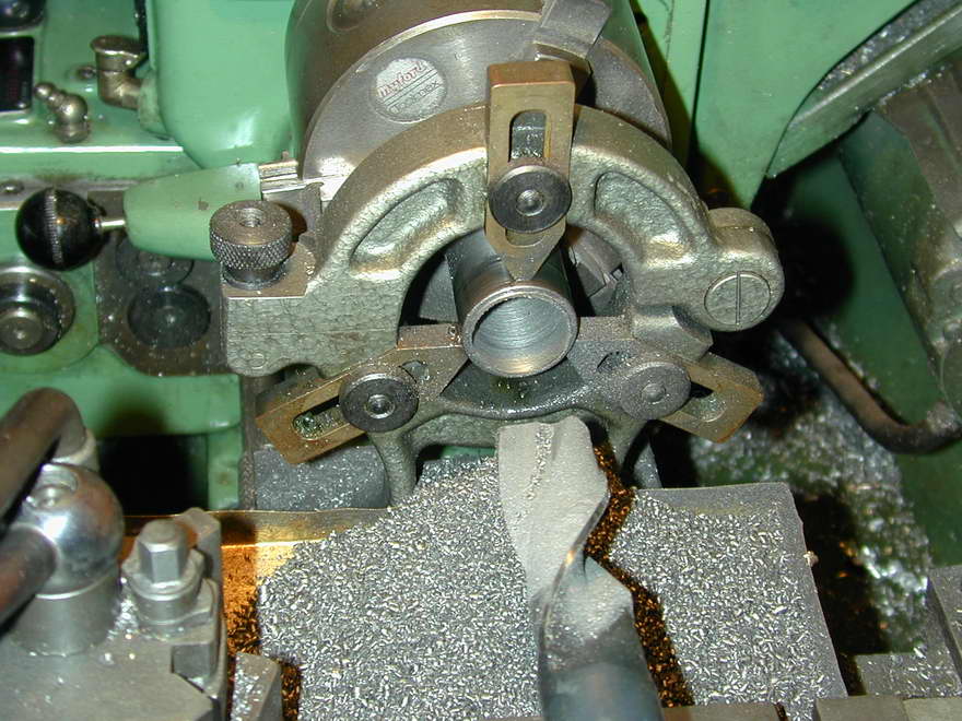
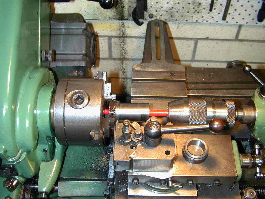 The liner is then parted off leaving the lip about 0.005" over-length so that it can be turned down to flush with the crankcase top later. The red rod is backup to catch the liner in case I fumble to job. After parting off, it is reversed, threaded thru the fixed steady and lightly gripped with a piece of 1" stock up the ID to prevent the jaws distorting the liner. A light chamfer is then turned around the lip ID to remove the part-off burr and assist piston and ring insertion.
That's all for the liner, so invest a good half hour cleaning up all the dirty, fine, cast-iron dust from the lathe and a thousand other unexpected places.
Piston
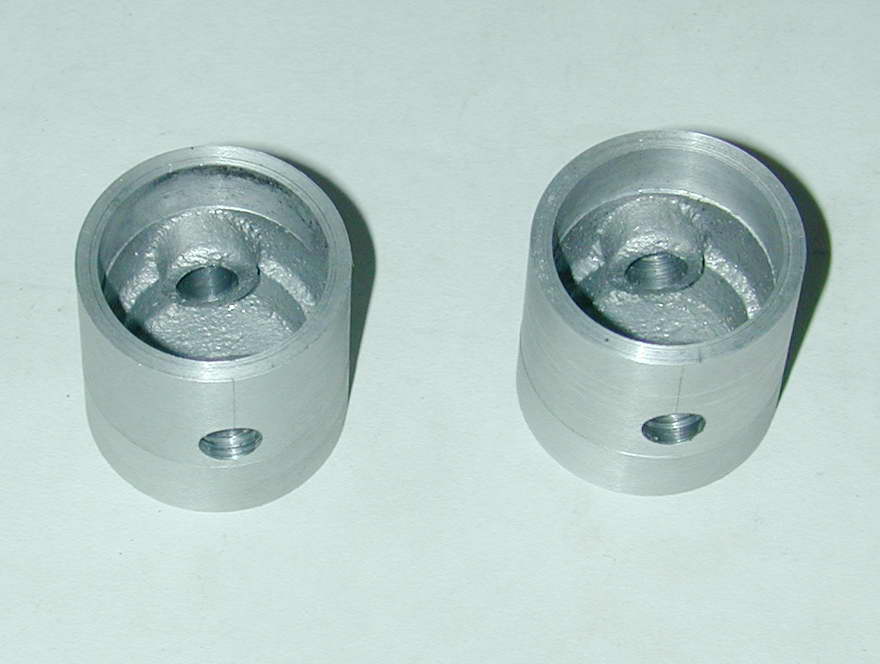 The piston is an aluminum casting with internal bosses for the wrist pin. It has no chucking stub despite what the old ETW instructions state. This imposes a degree of difficulty in devising a plan to accurately drill and ream for the wrist pin. Some research in the form of reading other ETW construction articles provided the perfect answer. This was so good, it has been written up as a How-to Tip which you can read via the preceding link. What we are out to produce is a reamed wrist pin hole that is precisely located on the piston diameter and parallel to the bottom edge of the piston skirt. At this point, the piston should be oversize in diameter and height. It can then be mounted on a special fixture for finishing the OD and cutting the ring grooves.
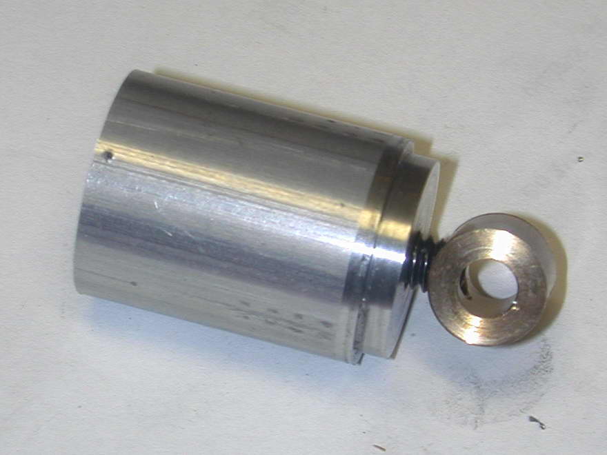 The fixture is a stub of 1" aluminum bar-stock that is chucked, drilled and tapped 1/4-20 as a convenient thread. The end is then turned to form a spigot that fits closely in the turned bore of the piston. It should now stay chucked until all operations are complete. As the piston skirt was faced at the same setting at which it was bored, then this face used as the reference for drilling the wrist pin hole, a threaded draw-bar and dummy wrist pin can pull the unfinished piston onto the fixture for turning the OD and ring grooves that will produce perfect alignment in all the right places.
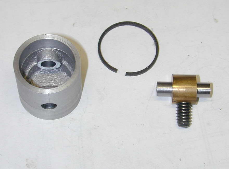 The simplest way to make the draw bar is in two pieces: threaded rod (cut from a 1/4-20 bolt), and a length of 1/2" material—brass in this case, as I had a piece handy—which can be drilled for the wrist pin, then cross drilled and tapped for the draw bar. Much easier, faster, and less wasteful than making it all in one piece.
 With the piston snugged down, the OD is reduced to the measured cylinder liner bore diameter, less 0.0025", plus or minus 0.0005". This provides the required allowance for the greater thermal expansion of aluminum over cast iron and so prevents galling of the piston. Obviously, a fit like this does nothing to help compression, but this does not matter as that is taken care of by the rings. The piston is then finished to length so the 0.062" ring grooves can be positioned relative to the crown. The kit comes with pre-finished rings. Their width was measured as 0.045", so the groove depth will be taken to 0.055" to give a decent cavity behind the ring allowing gas pressure following combustion to press the ring out onto the liner wall.
Cutting the ring grooves will raise a slight burr, but this does not matter as we now make a light skim from the crown, almost to the top of the wrist pin position, reducing the diameter by another 0.001", followed by another cut of 0.001" over the land above the top groove. These are to allow for the fact that the top of the piston will be hotter than the rest and hence expand more. The extra clearance at the top also helps get gas behind the top ring for starting compression.
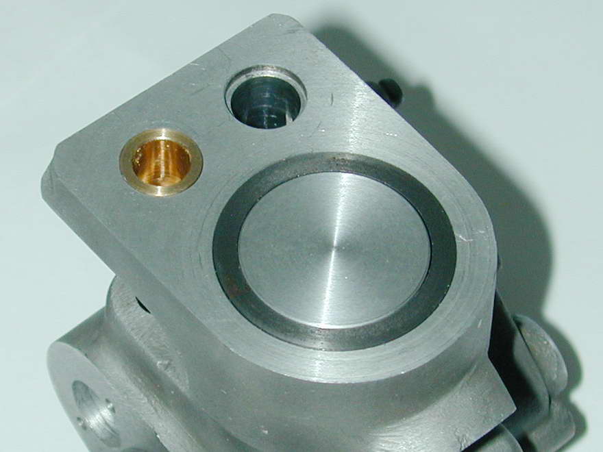 The last operating is to run a light chamfer around the crown and we are ready for a trial assembly, but don't un-chuck the fixture just yet. Assembly requires a bit of jiggling and is best accomplished by inserting the liner, piston and rod assembly in the crankcase so the rod big end is somewhere near the hole in the crankshaft follower. Then, with the nose piece removed, the crankpin can be threaded through the big end and jiggled around to pick up the follower with no regard to where the journal is. Lastly, the nose piece is placed over the shaft to center it. Check that the parts operate smoothly and that the piston crown is no higher than the liner lip at TDC. If it is more then a few thou proud, the piston can go back on the jig to reduce the crown height appropriately.

|
This work is licensed under a
Creative Commons Attribution-Noncommercial-Share Alike 3.0 License. |