Editorial

Happy New Year and Wombats! And a special thanks to all Model Engine News Members whose continuing support makes this site possible. This time last year, my little corner of the planet was in deep diabolicals regarding water, with dam levels below 20%; in effect, down in the mud. I'm happy to report that the situation eased during the latter half of 2008 and we are now up at about 42%, though it's stinking hot, mate! The global financial melt-down has not really extended its core rot to downunder, although we can't escape the flow-on effects from the problems in other countries and I'm afraid this year will be difficult for a lot of people. Still, I'm entering 2009 in excellent health, good spirits, and bountiful, unfounded optimism—life is good!
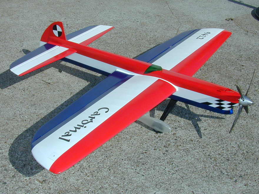
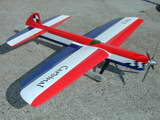 One reason for this may be that The annual break allowed me to finish off the Cardinal. In some ways, I'm quite pleased with it, but in others, I'm not completely happy with the result—let's call it the third nicest model I've ever made. The weight is great, 50 ounces, less tip weight and finish on the Bolly fibreglass wheel spats which arrived too late to get sprayed at the same time as the rest of the airframe. It's dead flat and the controls are free, flaps falling to down under their own weight. It has all the standard pro-stunt features: adjustable lead-outs, adjustable control neutrals, removable tank, tip and tail weight boxes, aluminum engine crush plates, and most important, dyed black nylon control hinges with a color scheme designed to make pattern judging easy with lots of reference lines. Power supplied by a Stalker 60 4RE, swinging a 12 inch, four-blade Bolly carbon fibre prop. So what's not to like?
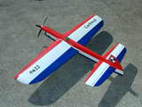 Well, the plan was a quick and dirty stunter, capable of winning at state level competition, with a serviceable finish, but no attempt at what American stunt fliers call a "front row finish". So only one sanded coat of dope and talc, and no silver undercoats sanded back and body puttied until the grain is gone. Instead, just a single coat of acrylic lacquer white, wet sanded back before spraying the finish white base coat. Then somehow I got carried away and started applying award techniques to a nice, but less than perfect surface. The result looks good from a distance, but less so up close. It could be taken as the effort of a builder who does not quite understand a few important things about finishing yet. It has five rubbed back coats of clear sprayed over Sig colored dope applied over the acrylic white base. All lettering is masked and airbrushed. I should have painted it with house paint and four inch brush to match the amount of surface preparation that went into it. Then, "One Coat Wally", the airport painter, once gave me sage advice: never brush when you can spray, and never spray when you can dip! Oh well, never mind. Next step is run-in the Stalker 60. First flight should be early January.
So far, I've managed to stick to my New Year Resolution of a few years back: no more resolutions! We are now into the second decade of MEN and nobody is more amazed at that than me. Our January issue has some good reading, IMHO, though news is a bit scant. As well as new pages, there are updates to some older ones that you can review using the Updates Page, though this page gets automatically regenerated each month, so if you are not reading this in January 2009, the updates will not be the ones that were done for this issue! Now that I've confused you utterly, on to business...
The Last Taipan
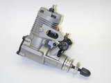
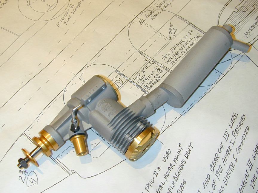
To start the new year, we have four "new" David R Jansen reviews, scanned and converted to HTML pages using optical character recognition software (OCR) from David's self-published book, Model Engine Designer and Manufacturer Profiles, which was reviewed here in the August 2006 issue. There are 112 reviews in David's collection, way more than I have time and patience to scan, so my policy has been to choose those which relate somehow to other material here, and for which I have examples of the engine in question, or can beg decent color photos of them from others. The Taipan 40 R/C is one of the former type and is quite an historic engine for Australians, being the very last Taipan, or the engine that broke the bank for the company, depending on your point of view. Either way, it is a superbly built engine.
With a international flavour, the other additions are the Mamiya 60 Ignition from Japan of 1949, the Nordec 10cc from England circa 1948, and the good old US made Mite 099 fixed compression diesel of 1947. This engine was one of the earliest CAD plan sets I produced for the Motor Boys and appears in all editions of our plans book. David Jansen's reviews are generally good work. They were produced to fit a print media format, so space was limited and hence they lack the depth and detail of an Adrian Duncan review, or one of mine. Imposed brevity can cause an author the simplify complicated details, resulting in information that while not wrong, is not exactly right either. Never the less, the Jansen reviews appearing here are worth reading, otherwise they would not be here!
349 Oops
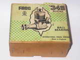
About half way through December, an email arrived from Adrian Duncan with some rather significant additions and corrections to his FROG 349 review. Adrian had received new information from Kevin Richards (England) who turns out to be every bit as expert on FROG as he is on ED. As well as allowing us to correct the estimate on the 349 production figure, Kevin's information provides a fool-proof way of distinguishing FROG engines made by Davies-Charlton Ltd from those made by IMA themselves. Adrian sent an addendum to the page, but really it needed some serious editing to incorporate the material, otherwise you'd be reading incorrect assumptions, followed by corrections. So forget part of what you read last month and click the thumbnail picture or follow this link to the start of the revised data and read through to the next major heading.
R-1830 Gets the Gold
We've been watching Ron Harris' R-1830 being built on these pages for quite a while—two and a half years, in fact—so I'm delighted to pass on the news that Ron's latest effort was awarded the Gold Medal in the annual Society of Model Experimental Engineers, aka SMEE (UK) awards. Ron also walked away with their Dead Easy Cup, awarded I expect, for the model judged to be anything but! This makes it three Gold's for Ron. The first was awarded to his scratch-built aero V8, similar to the Renault Airdisco fitted to the 1924 De Havilland DH 51. The second was for his Pratt & Whitney Junior. This is a scale 9 cylinder radial which, like the R-1830, was designed by Australian, Bob Roach, with cylinder heads cast by Vernal Engineering. Ron reports that both the Airdisco and Junior turn over happily at 6000 RPM and he sees no reason that the R-1830 should net do the same. I'm looking forward to seeing that exhaust collector ring belching smoke.
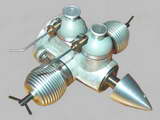
Model Engineering Museum Update

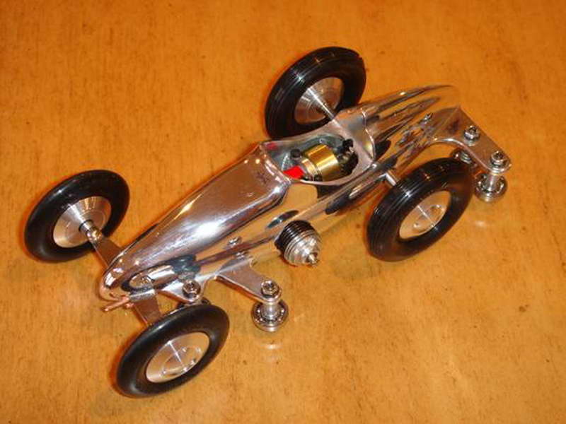
I'm not a model car person, but what model engineer can look at this photo and not want to know more? Details regarding it appeared in Paul and Paula Knapp's December Model Engineering Museum Newsletter (if you are not a subscriber, just drop an email to them). The little rail racer is powered by a Cox 010 and was built by John D Ellis (New Jersey) as a tribute to the late John Babcock. The top and pan are CNC machined from 2024 T-4 aluminum with a .028 nominal wall thickness. The rear axle ball bearing mounts are machined into both the top and pan along with the engine support and fuel tank bosses in pan. The engine support strap is 7075 T-6. The engine mount is CNC machined from navel bronze and the fuel tank is CNC machined from 360 brass with a plate soldered on bottom. The tank is held in place by three 0-80 Allen head cap screws. The vent and supply lines are .062 copper tubing and the engine has a spline-driven brass flywheel made of 360 brass. The custom cut bevel gears (3:1 ratio for torque) are heat treated steel and the ring gear is silver brazed on a form ground heat treated tool steel (h-13) rear axle. The pinion gear is secured with taper locking collar and one 2-56 Allen cap screw.
Other New Stuff
To start the New Year, we have a New Watzit that we rather hope that someone may have seen before and can supply more information on. Web site logs show that the Watzit entries are always popular. Sometimes we know what the engine is and sometimes we don't. And sometimes we only think we know what the engine is—as was the case with the Magnum that featured recently. Of the new one, we recognize some parts as commercial, but actual provenance is a mystery. It's even possible that it is a "joke" engine; one never intended to actually run, just look good. These certainly exist, but I rather doubt this is one of them.
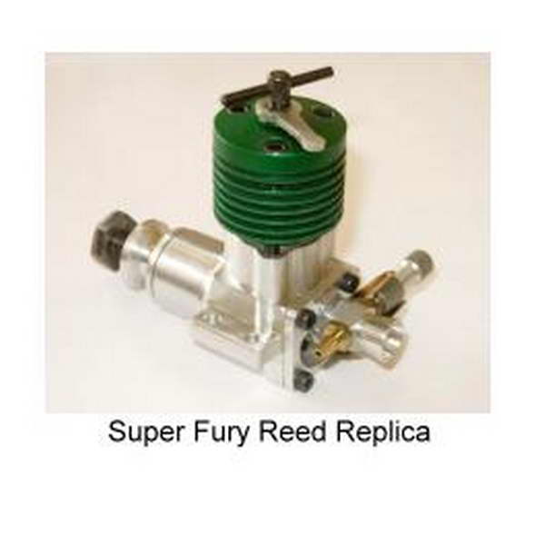
 The other major update is Model Engine Development, Part 3, by Gordon Cornell. This part details the drum valve development process. Gordon has been busy developing a reed valve version of the Super Fury which has recently had its first run. Preliminary results are promising, with performance superior to the drum valve version, but expect Gordon's normal meticulous approach to testing and refinement. In a recent email, Gordon mentioned that his modifications gave no significant power increase until he revised the cylinder porting. This confirms his reasoning that intake cannot exceed exhaust and that the cylinder porting has a marked effect on how efficient of the system. For the new replica, the reed valve intake port was located centrally in order to improve gas flow slightly. Gordon believes that few really understand the pumping and scavenge process, agreeing with independent experiments carried out by George Aldrich and Duke Fox, that reducing the crankcase volume has little effect, partly because gas flow is disrupted.
New Books and Magazines This Month
Our book this month is one I've been after for the better part of ten years. It was published in 1989 and was out of print by the time that I became aware of it. My usual source for second hand books is a consortium known as the Advanced Book Exchange (ABE for short). Their website provides a search facility over the inventory of what must be thousands of book sellers, worldwide—broader than the Amazon Marketplace, although the latter is not shabby either and forms my second point of attack if ABE fails. Initial searches on the subject failed utterly until quite recently when multiple hits were returned. I can only guess that being a book that would appeal to older modellers, they have been dropping off the twig recently and their prized book collections have passed into the market. Whatever the reason, I now have my own copy and am both delighted and disappointed.
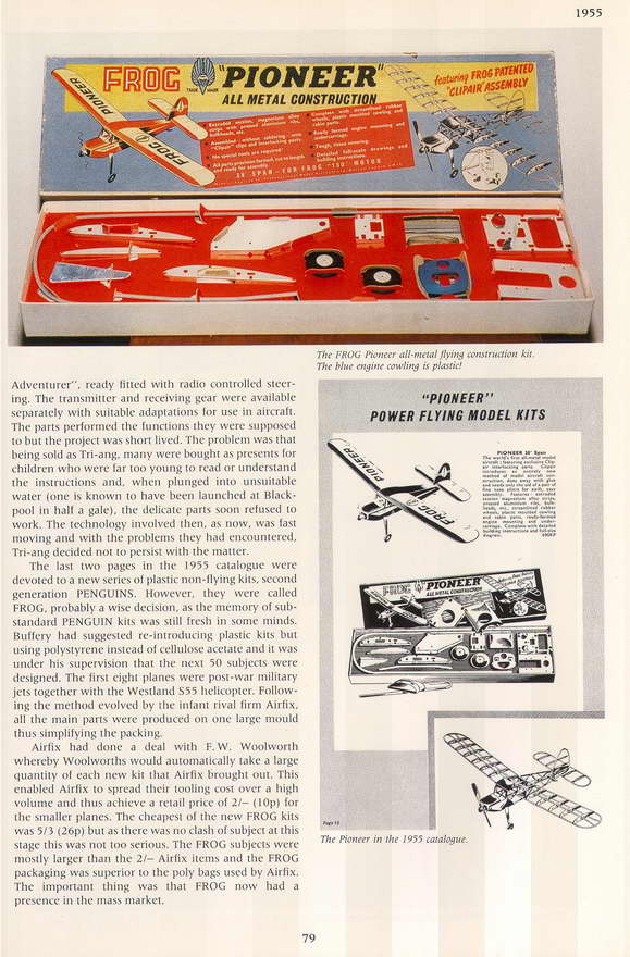
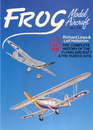 The book is FROG Model Aircraft 1932-1976, by Richard Lines and Leif Hellström, published by New Cavendish Books, 1989, ISBN 0904568636. The descriptive sub-title is The Complete History of the Flying Aircraft & Plastic Kits, not to mention engines, dolls, dolls houses, and the occasional towed artillery target glider! This is one of those gorgeous coffee table crushing tomes, hard bound with 272 pages containing well written text and copious illustrations in black and white and full color. The color photos and illustrations are not "plates", but are scattered throughout the book wherever the authors and their publisher seemed to think they were required.

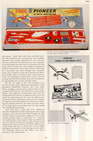
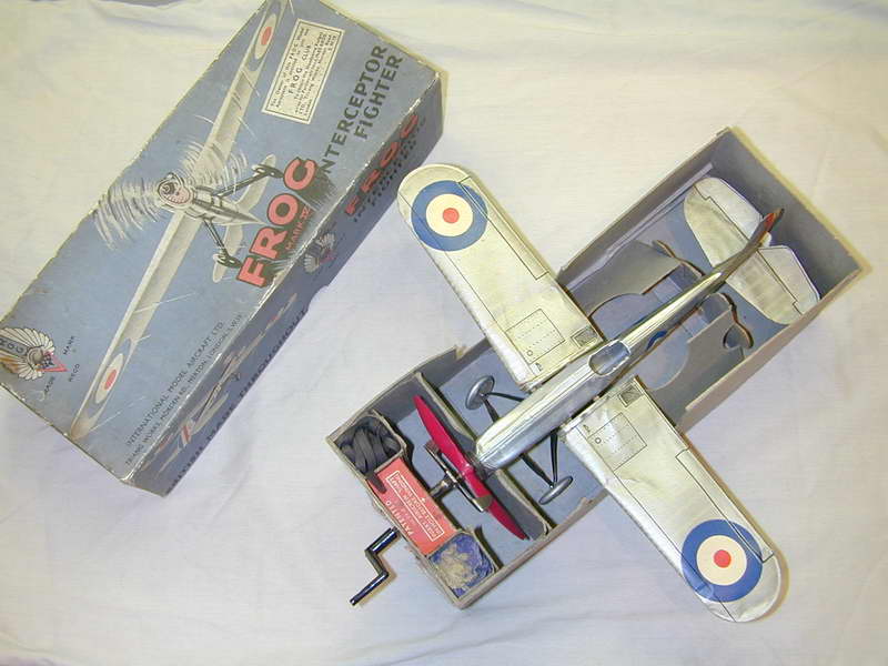
FROG was the trademark of International Model Aircraft Limited (IMA) and as we've mentioned numerous times in these pages, was an acronym for "Flies Right Off Ground". Like most acronyms, I suspect the name came first and the words second, although the founders, Charles Wilmont and Joe Mansour undoubtedly knew what sort of words they were looking for to describe their first product in 1932. This was a rubber powered ready to fly model that looked very scale-like, yet performed exceptionally well. It featured some highly innovative features, two of which were covered by patents. One covered the use of a 20:1 gear box between rubber motor and prop (No 353,927). This gave an increase in prop speed that provided good flying performance on a small, scale sized prop and somewhat moderated the "burst" given by all rubber motors at the start of a run. The other was for the geared up winder and cradle which was built into the box the model came in (No 374,203). This was required to cancel out the 1 in 20 reduction gearing you faced trying to wind the motor using the prop! A partial reproduction of these patents appears in the book, along with the FROG trademark and evolutions it went through over time. The photo here shows the Mk IV Interceptor in my collection which, using the book, I can at last date as circa 1936-39.
The text describes the complete history of IMA from its founding, through changes in ownership and fortune. I won't even try to prećis that here—it's too complicated. But it is worth mentioning that the foundation products, namely actual flying models, eventually became such a small component of company revenue that internally they were considered "cottage industry" and rather unceremoniously hived off in 1963 to AA Hales Ltd (see Adrian Duncan's FROG 349 review for some more detail on this). The big seller was their plastic kits, some of which even outlasted IMA with examples of the Vulcan and Valiant "V-Bombers" being produced, without the national markings, in Soviet Russia from the IMA moulds. A reprint in the book of a news story from the Daily Telegraph of April 13, 1985, tells how a Moscow toy factory had to stop making models of NATO war planes due to the outrage occasioned by the discovery that they were falling into the hands of good Soviet children. Shock; Horror. What is the world coming to.
The history reads well and appears both informative and authoritative, although being a coffee table book, it is not referenced, so there is no way of validating the accuracy. On the plus side, if it was academically referenced, it would probably be unreadable as well. So I'm delighted, but disappointed that the focus is placed on the static models rather than the flying ones. I guess this is explained by the volume of the plastic models and the fact they were the mainstay of sales, and possibly have been what stirred the authors' passion, rather than the balsa kits and engines. I was never really into plastic models, preferring the flying models and IMA kits were always excellent with a quality of parts and plans that to me, seemed above that of all the other British kits and certainly the Australian kits. This is not to say that the book does not give them comprehensive coverage, including some of the RTF rubber models I am far too young to remember (and I ain't that young). There's also the problem of finding unbuilt examples to photograph. But what there is, is good! I just wish there was more of it and less in the "Compendium of Plastic Kits". Still, I understand there are avid plastic kit collectors out there, so this book should be an absolute treasure to them. On reflection, this is still a five star  book. I notice you can get copies from Amazon, and it looks like New Cavendish has done another print run, if your finances will stretch to it at £35.00, plus shipping for a half kilogram of book.
Engine Of The Month: Ace 0.5cc Diesel
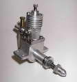
This little guy has been on the radar for quite a while. It's an ACE 0.5cc diesel from the very early days of British diesels and has Motor Boys written all over it. A 2D CAD plan set was commenced in October '07 using some almost decipherable sketches Ken Croft sent me some time back. Although all the parts are drawn, they still need dimensioning, a process that I find takes more time and effort than drawing and checking the parts themselves. But Adrian has one and sent a review in for the January issue, so I got down and made an earnest effort to finish up the plans. I was not 100% successful as the drawings are still dimensionless, but at least the General Arrangement is done so readers of Adrian's ACE Review will be able to follow his description of the construction details. If I get the finger out, the plans will get finished and patterns made and dispatched to Roger for making castings Real Soon Now.
Tech Tip of the Month
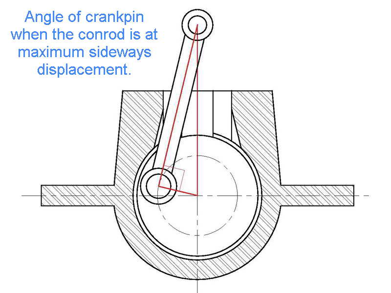
It's hard to categorize this month's tip. Is it a How-To, a Frequently Asked Question, an obscure piece of engineers' pub trivia, or what? I was reminded of it while completing the 2D CAD drawings of the crankcase for the ACE 0.5cc diesel. The rough pencil sketches from which I'd been working, made from an actual example, showed what looked like Schnuerle transfer passages in the case, but (one) the ACE is just a very conventional cross-flow engine, and (two) there were no ports in the liner at the location of these extra case passages, so what were they for? The obvious answer is they provide sideways clearance for the conrod in its travels. To me they looked way larger than required and while they would do the job, their size also reduced primary compression and hence, the pumping action of the engine (not that it matters greatly as the engine runs just fine). This led me to determine just what size they needed to be and reminded me of a question I've answered by email a couple of times: what is the angle of the crankpin at the point where to conrod is at its maximum sideways deflection?
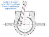
The answer is simple: there is no set angle for this! It depends on the conrod length and throw, which will obviously be different from engine to engine. Maximum sideways displacement of the rod occurs when the angle formed between the axis of the conrod and the radial on which the crankpin is located are at right angles to each other. The drawing should make this clear. From this, we can easily determine the angle and depth required to accommodate the conrod's journey. The Big End may be another story. In this case, as it fits entirely inside the crankweb disc, no further modification of the clearance channel is required. Had it been larger, there may have been a problem, but generally, this is not the case except when the rod has a screwed-on big end cap.
Luckily good old Hypotenuse makes this calculation very easy, even if you are not a CAD user. We know, or can easily measure, the stroke and the distance between centers of the conrod. The distance of the conrod little end above the shaft axis at this point will be the square root of the sum of the square of the "between centers" conrod length and the square of one half the stroke (often called the crank throw). If you really want to know the angle the crankpin will be at, relative to the horizontal plane, it is simply the angle whose tangent is given by the throw divided by the rod length.
It is worth mentioning that if the engine geometry is asymmetric—which is to say that the axis of the cylinder is offset from the vertical plane that lies on the crankshaft axis— Then the rod clearance channels will be asymmetric too, but if you are designing an engine with this feature (called "Desax"), you probably don't need to read tips like these. Solutions for all geometries are provided in Gordon P Blair's books, Design and Simulation of Two-Stroke Engines, and Design and Simulation of Four-Stroke Engines. These are as good as they get for those involved in engine design, or just for reference, though readers without a good grasp of mathematics may find them heavy going.
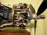
Airnocker
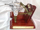
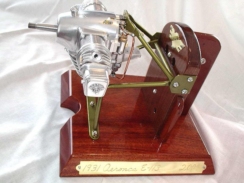
Finally, for those who wonder why the prolific Les Stone has been quiet lately, here's the explanation: a quarter scale Airnocker, sorry, Aeronca E-113, designed by the late Les Chenery. The actual engine dates back to 1931 where it powered a lightplane affectionately called the "Flying Bathtub". The unusual shape of the engine is due to the fact that it was designed to actually form the front of the aircraft, without any cowling! Although a US design, a version of the E-113C dual ignition variant of the engine was also built under license in England by J.A Prestwitch and Company Ltd, who called it the J.A.P. Model J99. Les started this one in April of 2008 and set a realistic goal for completion of January of 2009. Les reports that he still has exhaust and intake pipes to be formed, carburetor heater to be made, along with mounting and control linkage and also some kind of a choke arrangement, final work on the distributor, fuel tank with brackets, etc. When complete, we'll do a feature on the engine.
 The Last Taipan
 Editorial


