The Ace 0.5 cc Diesel
by Adrian Duncan
 |
 |
 |
| Click on images to view larger picture. | ||
History
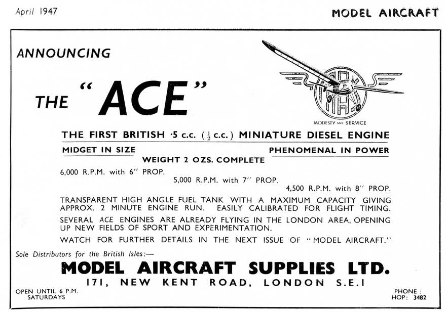
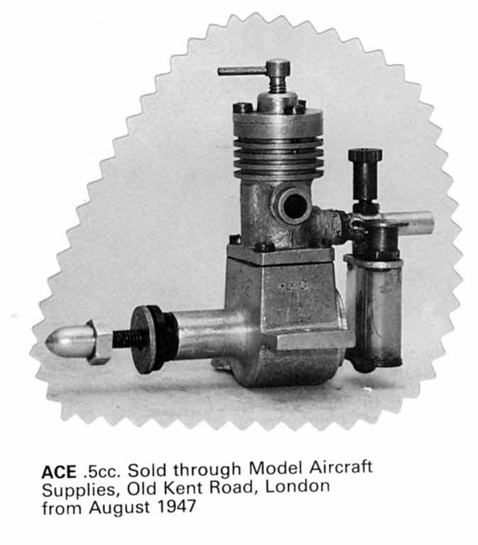
The ACE 0.5cc diesel was commissioned by Harry York, owner and manager of Model Aircraft Supplies Ltd, 171 New Kent Road, London SE1. The first press announcement for the engine we have been able to find appeared in the April 1947 issue of Model Aircraft. This one-third page splash is actually a pre-announcement, although it states that prototypes were in the field at that time. Note too the clever interplay of the company name, leading letters in the logo, and the tie-in to the company motto.
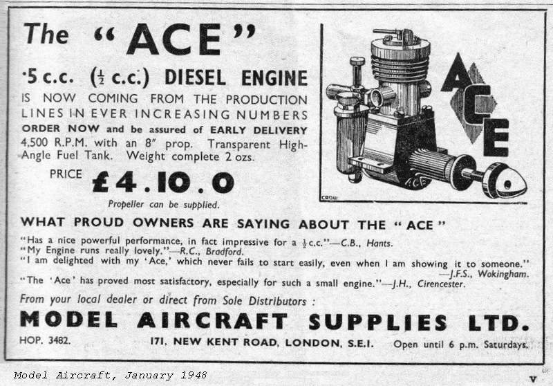 The first actual advertisement for the engine appeared in the June 1947 issue of Model Aircraft carrying the price £4-10-0. Clanford's A-Z dates the release as "..starting from August 1947". Col. CE Bowden's 1947 book entitled Diesel Model Engines names the originator of the Ace as an old aeromodelling friend of his, one H York (first edition, page 42) and states that the engine was "just becoming available" at the time of writing (page 63). Ron Warring's 1949 book, Miniature Aero Motors, lists the engine under the table of British Diesels, but footnotes the entry as "No longer in production". So we can say that Britain's first .5cc diesel appeared in mid 1947 and lasted about two years.
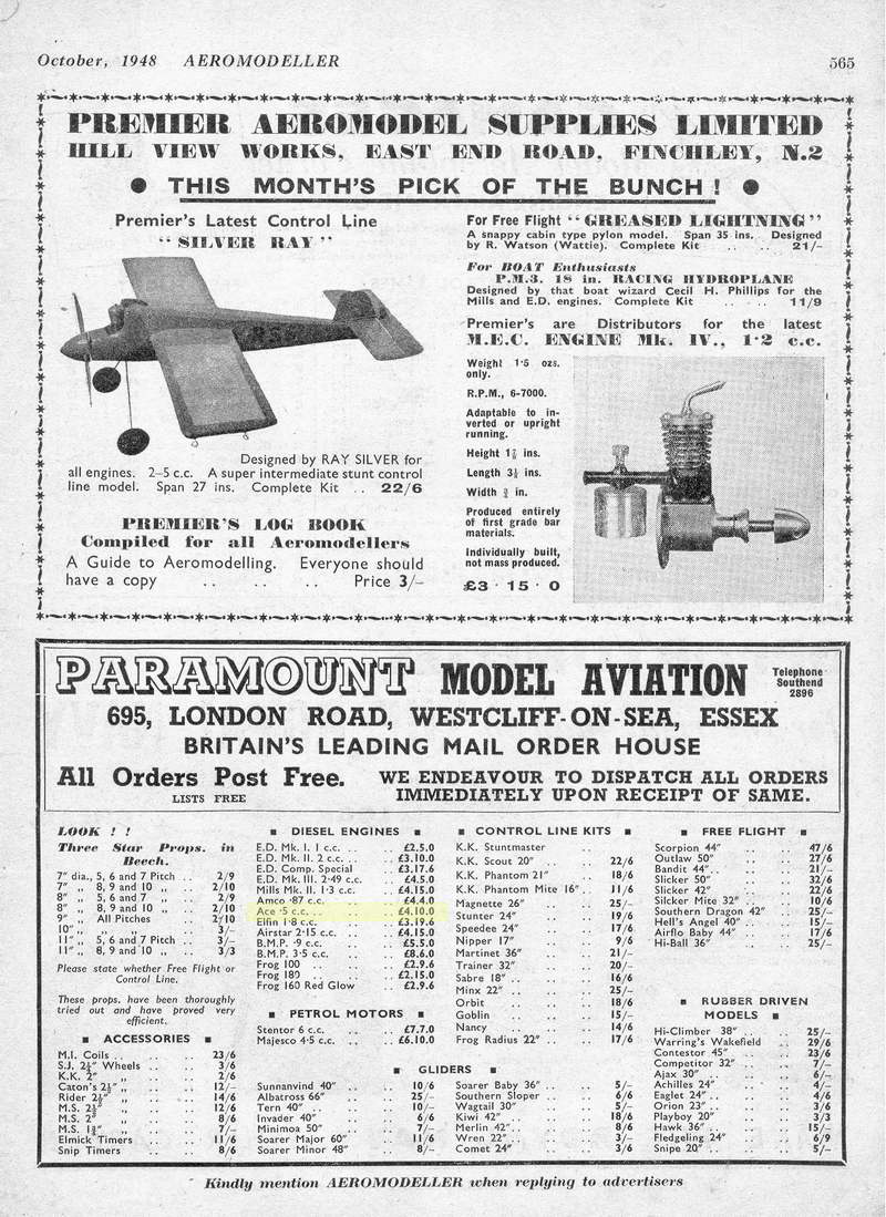 Harry York's Model Aircraft Supplies did not advertise in Aeromodeller, although the engine did appear there listed by a company called Paramont Model Aviation, of 695 London Road, Westcliff-on-Sea, Essex. The first appearance of the Ace .5 in their advertised products was in the April 1948 issue, carrying a price tag of £4-10-0, the same price as listed earlier by Model Aircraft Supplies. The engine remained in their list each month through October 1948, followed by one later, isolated appearance in May 1949. It also appeared once only in the Henry J Nicholls Ltd Aeromodeller advert of February, 1948.
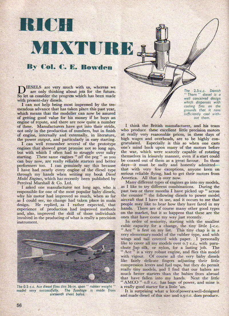
At this time, Britain had two monthly publications dedicated to aeromodelling; Aeromodeller, and Model Aircraft. The latter was "The Journal of the SMAE"—the Society of Model Aeronautical Engineers being the body responsible for sanctioned competition, records, etc. There was a degree of competition between the magazines and some manufacturers and retailers sided more with one than the other. It appears that Model Aircraft Supplies restricted their advertising to Model Aircraft, so it is hardly surprising that the magazine supported their advertiser with Col. CE Bowden mentioning the Ace in his Rich Mixture column of March 1948, calling it a "very robust engine" that flew his 36" test model "with vigour". No mention of the engine has been found in Aeromodeller.
So we can say that the engine was most likely released in 1947 (Bowden, Clanford), may have been available as late as May 1949 (Paramont), and was almost certainly out of production later that year (Warring). As such, the little Ace would enjoy the distinction of having been the first British production engine of 0.5 cc displacement. It had of course been preceded by smaller diesels such as the jewel-like 1946 French-made Allouchery �clair 0.16 cc and was quickly followed by a number of smaller British-made engines such as the Comet 0.4 cc, the Kalper 0.32 cc and the 0.25 cc Kemp Hawk Mk I diesels, all introduced in 1948. But if the it was available in 1947, it would be the clear forerunner of smaller displacement diesels in Britain and remained the sole production example of half cc British diesel until the 1951 introduction of the 0.55 cc Allbon Dart Mk I which heralded a spate of further half cc production engines from Elfin, Frog and ED (and much later, Allbon Saunders).
Construction
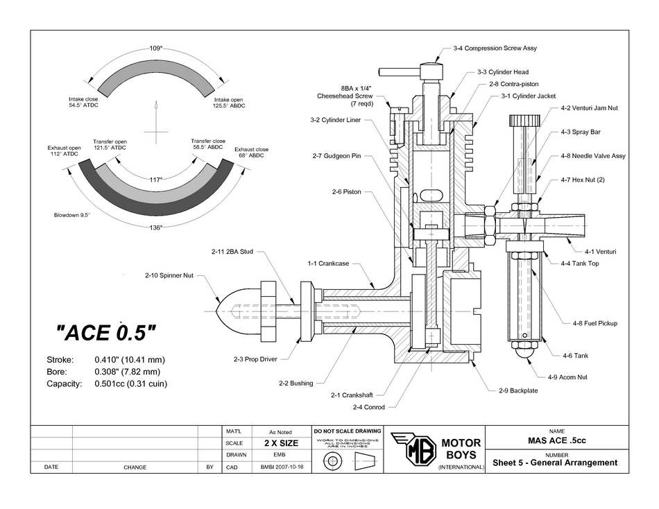
The engine features the usual long stroke of its sideport contemporaries, with a measured bore of 7.2 mm and a stroke of 11.1 mm for a stroke/bore ratio of 1.54 (a figure exceeded only by the Kalper and Foursome engines in my experience) and a displacement of almost exactly 0.5 cc. It weighs in at 2.125 ounces or 60 gm, complete with tank. When compared with its later 0.5 cc stablemates, it is undoubtedly on the bulky side and carries a fair bit of excess weight to boot—the original 1951 Allbon Dart weighed in at 1.25 ounces (admittedly without tank) and the ED Baby and Frog 50 models weighed 1.4 ounces and 1.25 ounces respectively with tanks. The later half cc models were also a good deal more neat and compact thanks to their die-cast cases, rotary valves and shorter strokes, and undoubtedly produced more top-end power as well.
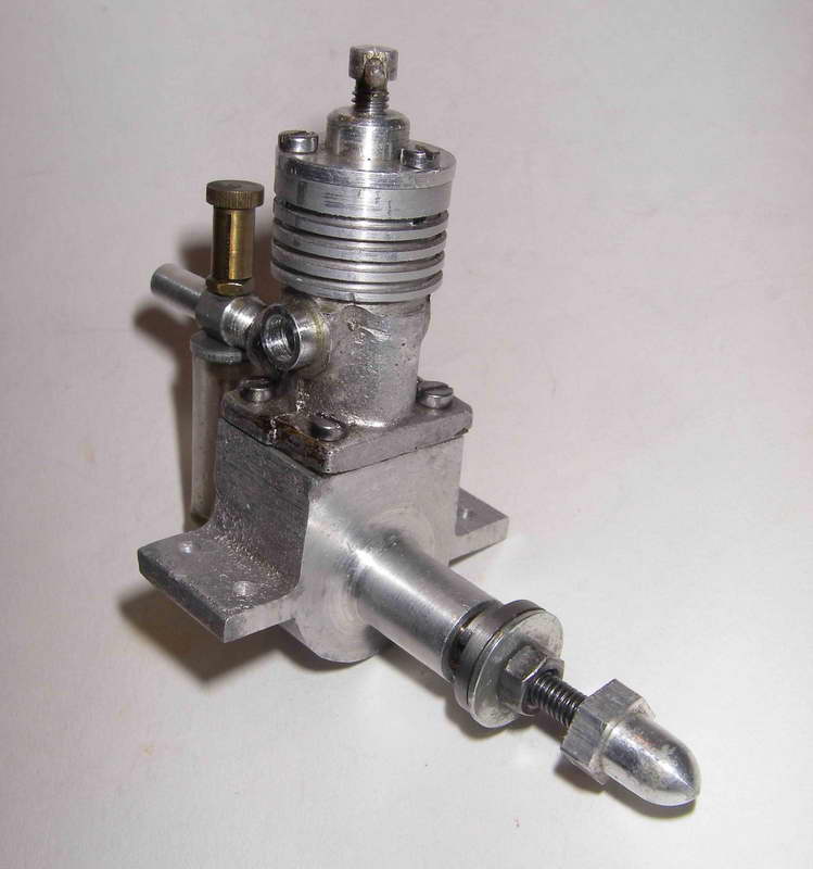
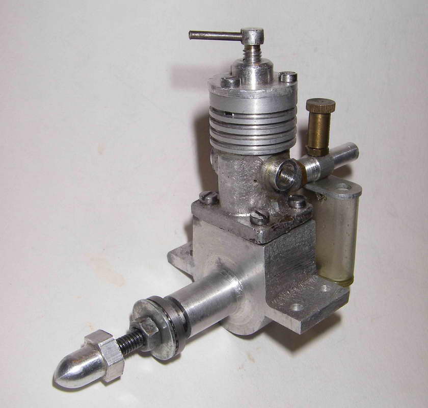
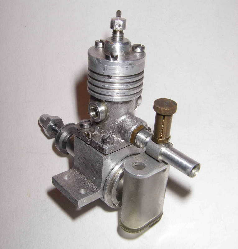
A major focus of these historical essays of mine must always be to correct any mis-information that may be out there. In that regard, it is necessary to set the late OFW Fisher straight regarding the construction of this engine. On page 41 of his book, he stated that the case was machined from the solid. It is of course possible that some examples were produced this way—I can't say for sure. All that I can say is that I have yet to see an example which used a barstock case. Both the illustrated example from my own collection and the two other examples that I have examined elsewhere have sandcast cases. Admittedly, the crankcase castings are machined over much of their external surface as well as internally—in fact the only un-machined exterior surfaces are the top of the mounting lugs, and the sides and underside of the crankcase. The sides of the case on my example have been rather crudely filed, presumably to eliminate some casting scale or flash. The undersides of the very substantial lugs are neatly machined to ensure a secure parallel mounting.
The only other casting used is that for the cylinder jacket. This is a rather agricultural-looking job with a certain lack of "tidiness" about it, especially at the parting line. The liner appears to be shrunk into this casting—at least, I can see no evidence of any other means of securing it. The bore was presumably finished after the shrinking-in process was complete. I've never tried to disturb the liner, so I can't comment further on this point.
Porting is quite rudimentary. Beginning with the induction arrangements, there are two very small circular induction ports drilled adjacent to each other at the rear of the cylinder liner. These communicate with the internally-threaded induction tube boss in the cylinder casting. The twin induction ports open fairly early as the piston rises, resulting in a relatively long induction period which presumably helps to compensate for the ports' small size. On my example, the two ports are drilled at slightly different levels in the liner, as a result of which their opening is staggered to a degree. It's possible that this was a design feature, but to me it seems more likely that it was an incidental error in the manufacture of this particular example. This is in keeping with the rather "hand-made" appearance of the engine in general terms.
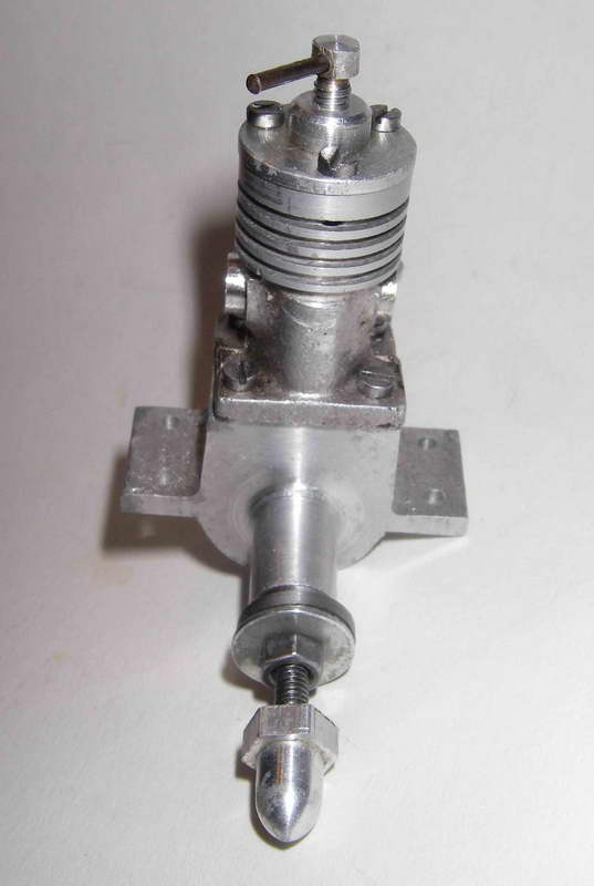
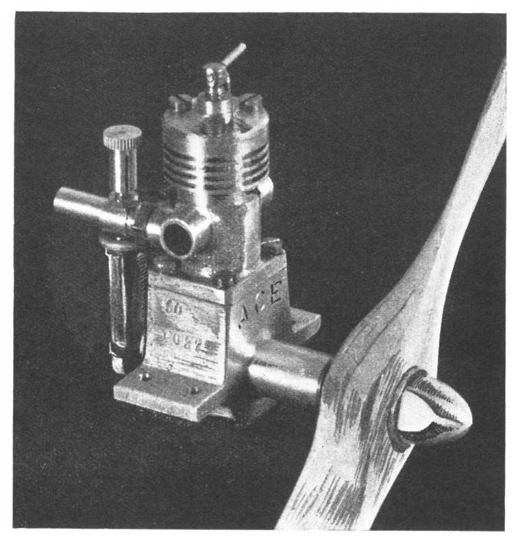
Transfer is accomplished through a pair of similar-sized drilled holes through the front of the cylinder liner, which are fed through a single transfer passage machined into a cast-in "bulge" at the front of the cylinder casting (clearly visible in the front view). These very small transfer ports open very late indeed and give the impression that they should represent a considerable impediment to the engine reaching high speeds given the very short transfer period that results from their location. Unlike the Mills and ED models, there is no "deflector" cut-away in the top of the piston. On the face of it, this arrangement is a clear recipe for inefficient transfer and scavenging. In fact, the transfer arrangements appear on detailed examination to represent the main limiting factor with respect to this engine's potential performance. But see on for performance comments below.
The provision of induction and transfer ports drilled fore and aft in pairs is probably mainly due to the desirability of ensuring that the gudgeon pin cannot foul these ports. As matters stand, the thin "pillar" between each pair of drilled ports is aligned with the gudgeon pin and prevents it from hanging up in the ports.
Exhaust ports consist once again of two adjacent drilled openings on either side which communicate with round exhaust bosses machined into the sides of the cylinder casting. However, these ports are quite substantial in size—too bad that the induction and transfer systems weren't similarly free-breathing. The exhaust ports open relatively late but still well before the transfers, giving a pretty good blow-down period prior to the commencement of the transfer part of the cycle. This doubtless aids the scavenging process.
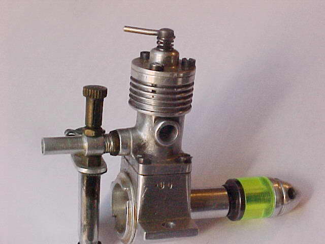
The fuel supply system is of some interest. The choke tube is a simple turning from bar stock aluminum which screws into the mounting boss at the rear of the cylinder casting and is secured by a brass lock-nut. It can thus be oriented together with the tank in any desired position. The choke tube has a very nice venturi section which tapers down from the rear to a constriction at the needle location and then opens up again towards the induction ports—very elegant!
In keeping with many contemporary British engines, there is no spraybar. Instead, the needle valve thimble screws onto an externally-threaded brass spigot which is drilled to pass the needle and screws independently into one side of the choke tube, ending more or less flush with the internal surface of the venturi. The separate brass fuel pick-up tube screws into the opposite side of the venturi. The needle simply passes through the spigot and across the otherwise-unobstructed throat section of the venturi to engage with the jet in the fuel pick-up tube on the other side—in effect, a standard surface jet needle valve system. The needle valve thimble is tensioned by being split in the usual manner.
The brass fuel pick-up tube extends down to the base of the tank, and a threaded portion protrudes through the tank base to allow the tank to be secured using a very neat acorn nut. A nice touch is the use of a gasket underneath this acorn nut to eliminate any chance of a fuel leak—disastrous in such a small tank as this. Two small holes are drilled horizontally into the pick-up tube at the tank base to supply fuel to the system. A threaded portion of the pick-up tube at the top screws into the choke tube opposite the needle mounting, and a nut mounted on the exposed portion of this thread within the tank serves both to lock the system in place and to secure the aluminium tank top to the choke tube in any desired orientation. Again, very neat!
The plastic tank itself is well worthy of comment. It has a most unusual narrow "race-track" section, as can be seen in the photographs, almost like a section cut from a plastic toothbrush tube! I assume that there are two reasons for this. One would be to ensure that the tank drains to the "last drop" regardless of the attitude of the model during its climb, and the other would be to create a constant and (more importantly) relatively small section so that motor runs could be timed with sufficient accuracy for sport free-flying (for which the engine is clearly intended) by noting the appropriate level in the tank at which to launch—not so easy to do with a tank of larger section and greater horizontal extent. Overall, the makers appear to have put a lot of thought into the fuel system of this motor—it really is rather well designed for the intended purpose.
A few more descriptive points—the one-piece hardened steel crankshaft is very well machined and finished. There is no attempt at counterbalancing—a plain disc crankweb is used. The shaft fit in the main bearing is superb—very free, but with no detectable trace of play, even when dry. The bearing itself is bronze-bushed, and should outlast the rest of the engine by a country mile. The rod is of hardened steel, in common with many British engines of the period, and here the design can be fairly criticized on the grounds that there is far too little material at the small end of the rod, which results in a bearing on the gudgeon pin that is far shorter than ideal. I would expect this end of the rod set-up to wear fairly rapidly, although the engine's small bore and relatively modest performance would doubtless do much to delay the onset of any such effects.
Another criticism that may be mentioned at this point is the main bearing housing—this appears to be rather flimsy given its very thin walls and the complete absence of any supporting webbing. However, any model in which this engine might be expected to have flown would have been both slow and light, with commensurately low crash stresses. So perhaps all would have been well in actual use.
On the illustrated example, the fit of the cast-iron piston in the steel cylinder is again truly superb—no trace of excessive friction (a real killer in the smaller sizes) but also an outstanding compression seal. The cast-iron contra-piston is also extremely well fitted. Overall, I have to say that despite its rather rough-and-ready external appearance, the engine is extremely well made where it counts.
An unusual feature of the engine is the fact that the comp screw is of aluminium alloy, with a steel tommy bar. The comp screw naturally operates in the machined alloy head, and I must confess that light alloy running under stress in light alloy has never recommended itself to me as an ideal combination. There's little or no detectable wear on the example illustrated, but this can readily be explained by the fact that this example has never been mounted and in fact appears to be almost unused.
The steel prop driver is slotted at the rear to engage with a pair of flats machined in the front of the shaft where it protrudes from the main bearing. I prefer a taper fit here—the arrangement used in this engine appears to me to create a substantial stress-raiser at the front of the shaft. But the ED 2 cc models use a similar system, and I've never had any trouble with them. touch wood!
The provision of the conventional prop nut and steel washer along with the cute little alloy spinner nut is interesting. I don't even know if this spinner nut is an original feature, but assume that it probably is—I've seen one other example with exactly the same accessory.
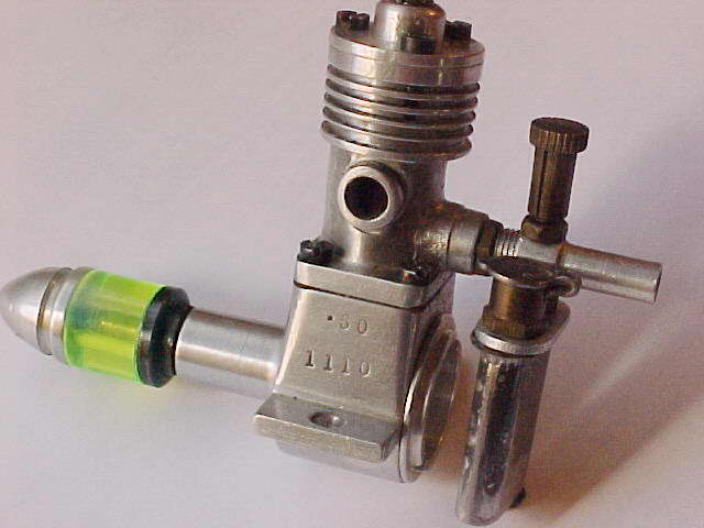
The illustrated example from my own collection bears no identification and no serial number. This is in contrast to the one pictured on page 41 of Col. Bowden's book, which has the name "ACE" stamped onto the front of the case and also has a serial number of some kind stamped into the right side of the upper crankcase above the mounting lug. I'm not clear on the explanation for this, but the inference is that the engines were inscribed at the outset but that this practise was discontinued later, most likely for reasons of cost. The example illustrated by Bowden must be one of the earliest examples made, and the makers may have taken more trouble to identify their product with the introductory "ambassador" models than they did later. Either that, or my own example is a very convincing repro made at some point by person or persons presently unknown... if so, it's quite a bit more "agricultural" than the typical latter-day repro!
Operation
Regardless, how does it run? Well, it's now time for me to do some grovelling with respect to all the comments that I made earlier about the anaemic breathing of this engine. As I think I've made quite clear, it really has no business running with any hint of power, but darn it, just to spite me, the thing does run that way! It has a level of performance that is quite out of keeping with the apparently restricted transfer system! I'd run it before, but had never taken any rev figures or checked it out over the operating range. While researching this article, I set it up again and checked it out on a few different props, with the following results:
| Prop | Speed (rpm) |
|---|---|
| Taipan 7x4 nylon | 7,900 |
| Windsor 6x4 glass-fibre nylon | 9,600 |
| Cox 6x3 glass fibre nylon | 10,200 |
 Now, what's this apparently anaemic little beastie doing giving performance figures like that?? Heck, the later and far more refined ED Baby only did 7,500 rpm on a 7x4 and 10,800 rpm on a 6x3 in its "Aeromodeller" test, while the Frog 50 managed 7,200 rpm on the 7x4, 10,850 rpm on a 6x4 and 11,800 rpm on a 6x3. Admittedly, the props that I was using on the Ace were modern props which are presumably faster than their early 1950's counterparts, but still, the little Ace undeniably has a very sprightly performance by the standards of its day, and certainly had plenty of power to fly a model.
The engine starts very easily provided you don't flood it. A single choked flick is all that is required—any more, and it's flood city. And clearing a flooded situation with this little beastie is definitely tricky—best avoided. But if you get the choking right, it's a one or two flick starter every time. And once going, the engine runs very smoothly—no indications of transfer strangulation here! It also responds very well indeed to the controls—the optimum settings are dead easy to establish. Not only that, but the engine can be throttled back very effectively and dependably with the controls, which would have been a great advantage for trim flights, etc. On a rich needle with reduced compression it keeps running quite smoothly and dependably, albeit a lot more slowly. The tank supplied with the engine gives a leaned-out run of some 80 seconds—plenty for the sport free-flight application for which the engine was doubtless intended. A small bottle of fuel (fuel was often supplied in bottles in those days) would have given a lot of flying with this engine!
The little Ace would really have made a very acceptable power plant for use in small free-flight sport and scale models, and that was doubtless its intended use. There's no point in trying to push it to run too fast—it's probably pretty much done by 10,000 rpm. Better to use a somewhat larger prop and take advantage of the engine's excellent torque rather than its peak power. A wide-blade 7x4 prop that pulls the static revs down to around 7,500 rpm or so would appear to be the ideal prop to use—the engine clearly has the torque to deal with such a size, and actually out-turns its later compatriots on a standard 7x4 prop (possibly due to the different prop designs involved, admittedly).
At this point I have to admit that Col. Bowden and I are not in agreement on the subject of props to use on the Ace! The good Colonel was always a fan of running his engines at low revs regardless of their actual peaking speeds, and he used an 8 inch diameter propeller of unspecified pitch on his Ace, noting on page 42 of his book that it turned that prop at 4,500 rpm! Sounds quite believable, but it's clear from my own tests noted above that the Ace was quite happy to run a lot faster than that and that an 8 inch airscrew would definitely over-prop it in terms of achieving maximum available performance.
Another point in the engine's favour is the noise level—the relatively late exhaust opening means that it's remarkably quiet, even having regard to its small size. The use of drilled exhaust ports doubtless has something to do with this too, since drilled ports open progressively rather than all at once, and on this design they open quite late after the combustion gasses in the cylinder have had a good chance to expand and hence lower the exhaust pressure in the cylinder. Whatever the reason, the operation of this engine would have created few complaints about noise!
Conclusion
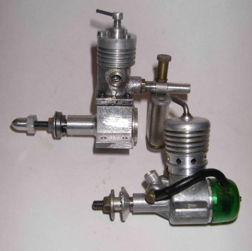
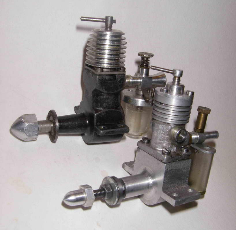 It's hard to see how the engine could have survived the competition from Mills after they introduced their original machined-case S 75 model in 1948—as the comparison photo shows, the Mills was very little larger in a physical sense, weighed somewhat less, looked far more "professional" on the outside and offered far greater performance while retaining the good starting qualities and flexibility of control which must have recommended the Ace to its purchasers. I'd be surprised if the Ace lasted much if at all beyond 1948.
How many were made? In a nutshell, who knows?? Not that many by, say, ED standards, I have no doubt. But one does still see these engines on offer among collectors from time to time, indicating that a reasonable number of them made it into the hands of the modelling public. There's presently no accumulation of serial numbers to help us, so we're stuck for now with speculation on this point.
In summary, an interesting and well-made little engine which is a pleasure to operate and which led the way in the development of smaller British-made engines, being thus deserving of our recollection and respect. It is completely unpretentious when it comes to the surface trimmings but is very well made in the essential areas and runs with surprising vigour. The design could perhaps have been improved still further by freeing up the transfer and exhaust, thus improving scavenging, but as a quiet and flexible sport flyer the Ace 0.5 cc offered its owners all that was required by the standards of its day. A gold star to Mr. York!

This page designed to look best when using anything but IE!
Please submit all questions and comments to
[email protected]
|
Unless otherwise expressed, all original text, drawings, and photographs created by
Ronald A Chernich appearing on the Model Engine News web site are licensed under a Creative Commons Attribution-Noncommercial-Share Alike 3.0 License. |

|