| Unless otherwise expressed, all original text, drawings, and photographs on this page created by Gordon Cornell are licensed under a Creative Commons Attribution-Noncommercial-Share Alike 3.0 License. |

|
Model Engine Development
Part 3
-
 The Induction Process
 -
Drum Valve Induction - A Brief History
-
Development of the Drum Valve
-
Making a Drum Valve System
Click on images to view larger picture.
Hover for a description.
The Induction Process
where Vcc is the crankcase volume with the piston at BDC, and Vsv is the swept volume (aka Primary Compression ratio) ???

At this point, it is appropriate to review the effect which cylinder and crankcase pressure have on the induction process. In most naturally aspirated engines, it is not feasible to achieve a pumping ratio greater than 1.6 to 1. Using this figure as the base, the transfer ports should not open until cylinder pressure has dropped to 24 PSIA if blow-back is to be avoided. The descending piston has to create this level of trapped pressure before the ports are opened. Crankcase pressure on passing through TDC will eventually reach atmospheric pressure which is 14.7 PSIA. At this point the induction port should close.
The pumping stroke is limited by the opening of the transfer, or scavenge ports. The stored energy transfers the charge into the cylinder until crankcase pressure falls to 14.7 PSIA, at which point induction can commence. This can be timed to open before the scavenge ports are closed. The system can only take in or replace the mass which exits to exhaust during the scavenge process. The choke size provides a throttle which limits the maximum mass displacement. If the induction system has other throttling systems such as a reed valve, these can disrupt the flow leading to mixture strength problems. The ED Fury test report by Ron Warring refers to flooding problems that were experienced—in effect there are two throttles: reed and choke.
The reed acts in this manner because it responds to differential pressure and is not directly operated by mechanical connection to the crankshaft. The automatic induction system may be thought to be ideal and self compensating. This can be misleading because the reality is that the combustion cycle and timing actually determines the mass that can be displaced at any specific RPM. Hence the blow-down period determines the shape of the BHP curve.
As these port timings in model engines are fixed, it is unlikely that an automatic induction system can be made to produce the highest output. The reed system must be made to have the least possible throttling affect. This is completely contrary to some individual's concept of the application. So we need to create a system were both induction and cylinder ports are closely matched in terms of flow over the desired RPM range. In practice this has been achieved by the application of rotary valve induction.
Drum Valve Induction - A Brief History
 |
 |
 |
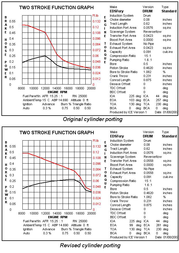
A drum valve system was made for the Super Fury but this did not provide a significant increase in power over the reed valve Fury. I have now reviewed this using my ICE program. See Power curves for the original Fury cylinder, and the first Super Fury item. This confirms that the primary reason for this was due to the cylinder porting - note the difference in exhaust timing. The induction timing closes later than the first production disc valve Super Fury which had sub piston induction, hence peak RPM cut off is less severe. Reference to cylinder development will be made in a subsequent article. Restrictions on space are such that readers should observe the timing and port area differences from these graphs - they include the applied test data.

The drawings provided below represent a close replica of the original drum system tested. It is obvious a number of improvements could be made. At the time I had not envisaged what is known as a drop-in inverted installation of the engine. With this arrangement, the engine is mounted with the top of the engine lugs against the top of the engine bearers. The position of the inlet of the Super Fury would prevent the jet assembly from passing between the engine bearers in this type of set-up. A drop-in installation provides easy access to the fully plumbed engine and fuel tank should modifications be required. This can be achieved on the replica Super Fury by the addition of a second drive hole or slot at 180° to that shown on the drawing, allowing the drum assembly to be rotated. This would provide a downdraft carburetion system giving a more consistent intake of fuel mixture since as well as placing the jet above the bearers, the intake would no longer be close to the exhaust ports. Hence the application can determine the most suitable arrangement.
Development of the Drum Valve
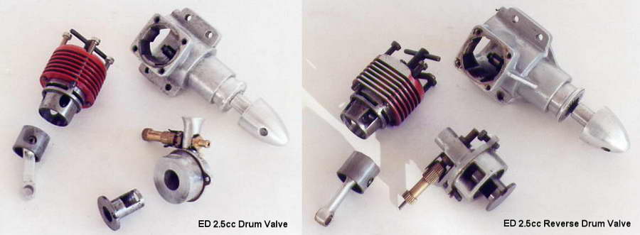 The logic behind the development of the drum valve was that many early engines applying a crankshaft rotary valve for induction suffered from crankshaft failures. A solution to this was seen in what became known as the drum valve, these early versions followed the design of the crankshaft rotary. Later I developed the reverse drum, or what might be called the centrifuge drum. As shown in this photograph, these alternative arrangements were first tested during the development of a replacement for the 2.5cc ED Racer in 1960. The centrifuge reverse drum induction was featured for the production version of my Dynamic 049 late 1961 shown in the photograph below. Subsequently, there have been many variations of this system.

Current International class Team Race engines apply the drum valve virtually without exception. There has been some controversy as to which drum system provides the highest efficiency. The debate is related to lubrication of the crankpin. This could be misleading as the implication is that lower oil content can be used with front rotary style drum releasing more BHP. The observation made is that the inlet gas flow does not flow over the crankpin with a reverse drum. In my view this can be misleading because maximum power is achieved with the highest inlet gas flow. The higher cylinder pressure that could be available from what I defined as the centrifuge drum may be the reason for the crankpin lubrication problems. There is virtually no thrust load with the standard drum compared to the centrifuge type. Many of the latter are simply not large enough to generate the increased flow of gas into the crankcase.
 The inlet gas must directly impinge itself on the inside of the drum so that this is forced into the crankcase by centrifugal force. It will not work by mounting the drum on an inlet choke the port functioning like a disc system. The reality is that one should not condemn a particular type because it has not been satisfactorily implemented. As already stated, research is required before original designs can be perfected. My first tests with the drum valve were disappointing because the inlet system was not matched to the cylinder porting. I obtained the highest BHP from the reverse/centrifuge type during 1959-1962.

The drawings for the drum valve system do not represent an optimized system, but are provided so that further investigation can be carried out. My pilot models indicate that performance is variable and at the present, no fuel consumption data has been established. There is an increase in RPM when placing a baffle or hand behind the engine choke. Further tests are required with the Drum Housing rotated 180 degrees (this was not evaluated during my original testing). Further investigation will be required into the most suitable fuel mixtures for the disc and drum variants. The next stage in development would be to create a centrifuge drum valve system so that merits of all systems can be determined. There are no short cuts in the development process; test results must be confirmed.
Making a Drum Valve System
As always it makes sense to plan the required operations. Making the Drum Housing from bar will require more than a single operation, hence it is constructed in three parts. This comprises a housing, choke and plug. The plug is not required for a marine or car version. The drum housing bore is applied as the means to secure this component for all operations. When bored right through it can be reamed to a close tolerance required for batch production. For marine versions an extended drum is introduced. This connects to the propeller drive by means of a hooks joint avoiding the need to wind a starting cord around this. It is also possible to provide a second drive shaft for model car applications.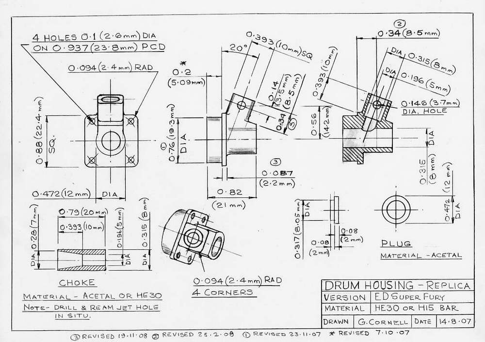 |
 |

For prototype purposes, the housing is best produced from bar stock — 1.25 inch square bar is just sufficient to provide an acceptable jet position. Use a 4 jaw self centering chuck and packing pieces to create a 0.125 inch offset (the same technique as applied when making a crankcase). Very few designs are right first time, so it is important in the development environment to make allowance for modification. There is sufficient material in the housing to enable porting modification. The separate choke reduces the size of the required bar stock and permits the fitting of a throttle control or other alternatives.
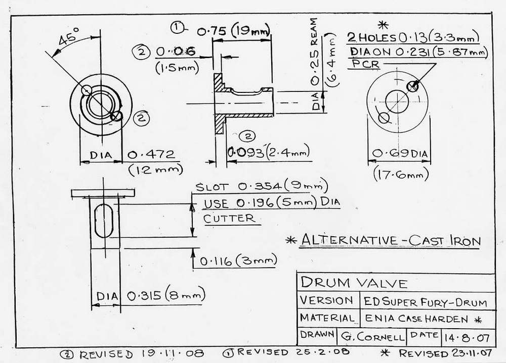
The Drum drawing provides for a crankpin drive hole of 0.13 inch (3.3mm) diameter - this requires a different crankshaft to the disc version. Some small changes would be required to apply the standard disc valve crankshaft. The larger hole required may break into the inner bore of the drum making positional accuracy difficult. Slotting from inside is an option, but is more complex. A continuous thrust surface for the conrod is preferable. Naturally a simple drilled hole is less expensive to apply and it can be used for tooling purposes to locate the drum in the correct position on a spigot to cut the induction port.

The port is cut using a 5 mm diameter FC3 cutter. The finished port width once the edges are de-burred will end up slightly larger. This is adjusted to provide the desired timing. When cutting rotary valve ports using this method, they tend to be larger than expected due to cutting through a curved surface.
Do not reject the drum system because my first tests were unsatisfactory. ICE exposed the defective cylinder porting and it now appears that it was my original appraisal which was not entirely satisfactory. You will require a drum system to compare to disc valve with the revised cylinder porting. The next induction system tried was the disc valve. Drawings and components of this are presented and appraised in Part 4. Details of the needle valve and spraybar assembly will appear in Part 7.


This page designed to look best when using anything but IE!
Please submit all questions and comments to
[email protected]