| Unless otherwise expressed, all original text, drawings, and photographs on this page created by Gordon Cornell are licensed under a Creative Commons Attribution-Noncommercial-Share Alike 3.0 License. |

|
Model Engine Development
Part 2


Click on images to view larger picture.
Hover for a description.
A New Engine
Having read the test reports by Warring and Chinn, it was obvious that virtually no development testing had been carried out on the Fury prior to production and that release of the engine had been premature. At that point in time, knowledge on testing and development was limited. Apart from running the engine and recording RPM, most manufacturers were satisfied if it started easily and ran. While the Fury did just that, it was not competitive in terms of price and performance. A problem for all designers is the continual upgrading of performance. In the competition environment, you must get the basics right before investing in expensive tooling. To my knowledge, no prototype Fury was seen at any model event prior to production. The question was, could this engine be upgraded to a competitive standard, and would it be economic to do so?
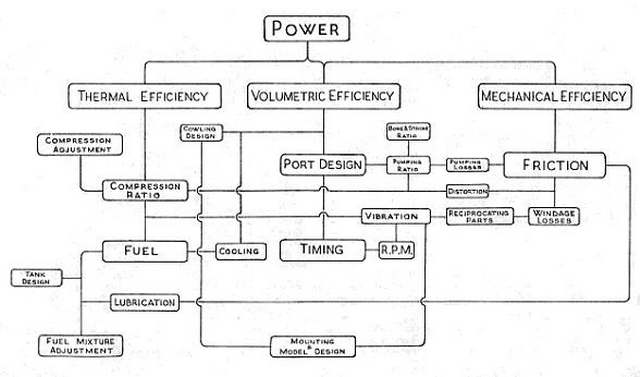
To aid my evaluation, I created a chart indicating how engine performance was modified by the Mechanical, Volumetric and Thermal efficiency. By observation of the chart, it was evident that there was a direct link between Volumetric Efficiency and the problem with the engine. Verification of port timing is very difficult by direct measurement, so a 10 times full size diagram was produced. This clock type of diagram is only useful to verify that the design dimensions have been manufactured correctly. Whilst port area could be established, it was not feasible to determine flow efficiency without testing. With the Automatic Induction provided by the reed valve, timing was pure guesswork, hence there was no means of determining if this was suitable for the desired RPM and cylinder porting.
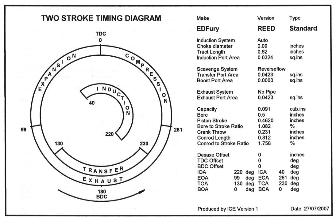
From the exhaust and transfer timing, it was apparent that the blow-down period of the Fury was substantially greater than my Frog 150R and TR 1.48. Today it is possible to evaluate this by means of a computer program like ICE, but this is only a comparator that evaluates the theoretical effect of changes. These predictions made may not be correct as:
- The coefficients of friction assumed for the engine do not match those in the test setup; or
- The gas flow orifice coefficients and scavenge efficiency are not as expected.
This is further complicated by the fuel and combustion setup. By modifying the values for these parameters in the ICE simulation, it is normally possible to produce a power curve which is a close match to the actual test results. In so doing you can provide some clues to the engines defects, or potential.
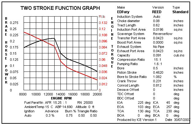 Using ICE, a power curve has been generated which is similar in shape to that of the Fury. Because of the extended blow down and retarded action of the reed valve, an exaggerated IMEP at low RPM is indicated. The reality is that a high percentage of the scavenge charge would exit through the exhaust due to the radial ports and reverse flow. Added to this, the Mechanical losses must have been much greater than those calculated by ICE. The inclusion of this information here is to establish if this would be applicable. It is very difficult to determine the precise parameters to be applied in such a small capacity engine. Changing the parameters permits one to determine how critical a particular feature might be. Many false claims and assumptions are made for design changes; it is important to carry out an adequate assessment of the problem presented. If you do not identify the problem you cannot fix it.
Testing had revealed that the engine Volumetric Efficiency was poor, hence no significant advantage had been achieved by mounting the crankshaft on ball bearings. The engine simply did not run at racing RPM. On examination it became apparent that the gas flow through the cylinder ports was restricted. As the bypass passages in the crankcase were cast in, changing these would involve further expenditure, however the real limitation was the size of the cylinder ports. These were cut using a pair of slitting saw cutters. The cutters used for this operation were 0.047 inches thick—the diameter was also excessive, restricting potential port width. A further problem was the cylinder could be assembled with the three transfer ports out of alignment with the cast-in bypass passages. This was further exacerbated by the fact that when the cylinder bolts were tightened, they distorted the cylinder. An improved cylinder was required.
In order to reduce tooling expenditure, a hardened steel conrod had been fitted to run on the hardened crankpin. This appeared to be too short and not really suited to high RPM operation. At that time we had already proved that forged RR56 alloy rods were the most satisfactory way to proceed.
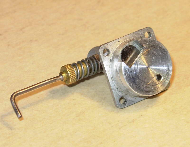
As the induction system appeared to be part of the problem, a decision was made to evaluate alternatives to the reed valve backplate. This was a modified ED Bee component and could be replaced if necessary. An efficient system is difficult to make in model size—the port area in relation to the reed spring rate was far to low in the original design. The pumping differential pressure must act upon the largest feasible reed valve area. This needs to be much greater than that of the choke, so a new backplate would be required to make this system satisfactory. Should an alternative induction system such as a Disk or Drum be employed, then a new crankshaft would be required. This however would not require new tooling, just an extended crankpin.
The Super Tigre G31 featured a drum valve induction system and had competitive performance. I also had experience of this system when developing the Frog 3.49 with George Fletcher. If this system was to be adopted, it would be recognized as a fresh design, converting to disc valve induction would not have the same impact. Unfortunately a drum valve system is heavier than either reed or disc and it is also more expensive to manufacture.
Finally, if the engine was to be successful in the market place, it would not be sufficient just to improve the performance, it would also need to be recognized as a new design.
An Alternative Induction System
")
A prototype drum valve system was produced and tested that revealed a number of unsatisfactory features of the Fury crankcase. As the crankcase was a pressure die casting and dies are very expensive to produce, it would not be practical to make significant changes to the basic design. The exhaust stack and rear cylinder bolt boss made machining of the crankcase difficult—it could not be simply faced off. The exhaust stack was a definitive feature of both the Racer and Fury. But at that time, silencers and tuned pipes were not fitted in model aircraft applications, so should an exhaust system be required, it would much better to produce this as a separate item.
Location of the jet assembly was compromised by the four backplate fixing screws. In addition, the cylinder bolt fixing screw bosses were inadequate and contributed to the cylinder distortion problem. At this time the crankcase was being cast from magnesium. The foundry had production problems with this material and when the machine shop returned a batch of castings, they refused to make any further magnesium items. The dies were quite massive, requiring a block and tackle to lift them. As castings were purchased in batches of one thousand, this could have been a contributory problem to casting quality as the dies would take a substantial length of time to reach operating temperature. I imagine from the number of unsatisfactory castings we received that no machining tests were carried out prior to dispatch to ED. In comparison, gravity dies produce satisfactory castings with a shorter warm up cycle if followed by further heat treatment process of the casting.
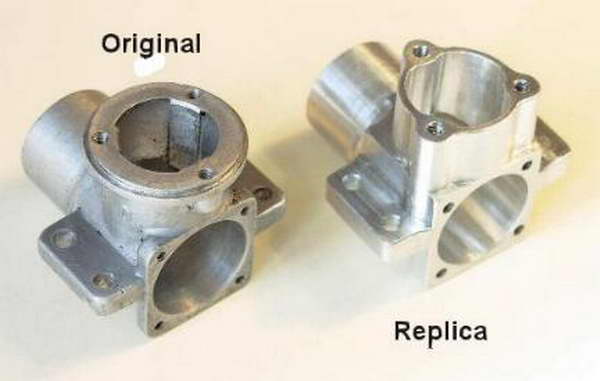
The Super Fury Crankcase
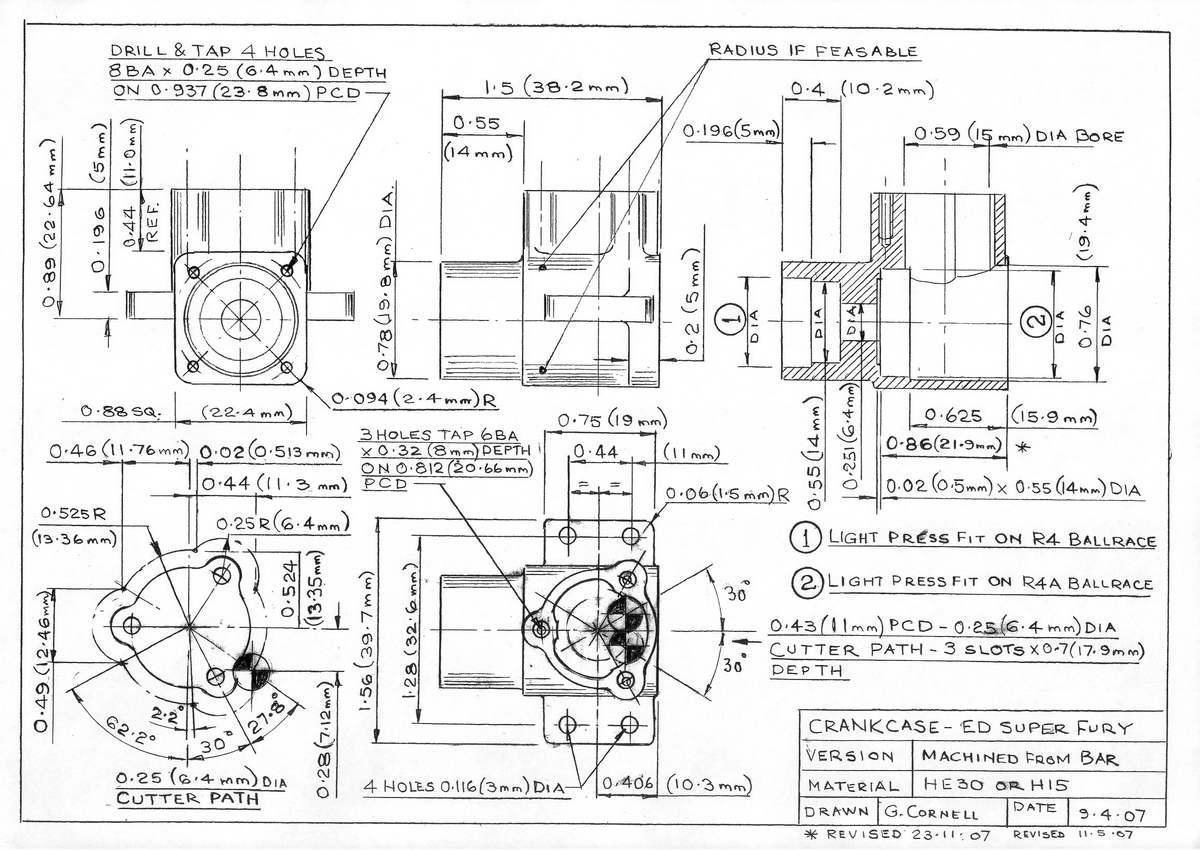
The crankcase is a crucial component because its structure must maintain the alignment between crankshaft and cylinder. Mounting bolts and cylinder fixings must not cause distortion or a loss of performance results. For the Super Fury, a decision was made to increase the size of the cylinder bolt bosses and the beam mounts which were also considered to be too fragile. There was a delay at the foundry in making these modifications to the dies. The first batch of one thousand Super Fury's had Magnesium crankcase castings. Subsequent production was in LM2 alloy. The exhaust stack was machined off to save weight and change the appearance. For replica purposes the crankcase is machined from bar stock. This avoids problems related to casting quality. The drawing of the replica crankcase reflects what changes should have been made prior to manufacture of the dies. The cylinder bolt fixings have been rotated 180 degrees so that the backplate mounting face can be machined.This crankcase will be used for all variants featuring the radial ported reverse flow cylinder, so readers can start by making this item first. For those with CNC equipment it represents an exercise in perfection of routines to produce a quality component in an acceptable time (routines for MPLUS are available, this being the system I use). Dave Robinson has produced a set of drawings in DXF format. These can used to create G code files within and applied by the Mach2/3 CNC system.
The drawing is dual dimensioned and the application of BA or modern metric fixings is optional. If you apply metric threads, these are slightly larger. The 1970 ED cylinders do not have the original alignment slots and may not assemble without modification. The replica cylinder cooling jacket has been modified to suit metric cap screws. The heads of metric cap screws can be reduced in diameter to minimize the counter-bore diameter required. BA socket screws are prohibitive in terms of cost, so my replicas employ metric fixings. Although adequate stock of BA fasteners exists to support this project—BA threads are being phased out in the UK. But if you wish to use them, WestonUk have stocks of the BA fixings required.
If you intend to use your engine in Vintage 1/2A team racing, currently you will have to use an original or cast crankcase. My tests reveal no significant difference in performance—the principal advantage being ease of manufacture and minimal tooling. Machining from bar stock is ideal for development purposes as small quantities of quality castings are difficult to obtain in the UK at this time (the originals were pressure castings).
Machining a Crankcase
 |
 |
 |
The important issue in machining this item is that both bearing housings are machined to be inline and concentric. In addition, the cylinder axis must be square to the crankshaft axis. This is much easier to achieve when produced from bar stock, weight being of less importance than accuracy. Castings would normally require more complex fixtures to achieve the required results.
Preparation
Before cutting any metal it is an advantage to plan how the object is to be produced. A complex item such as the crankcase will involve a sequence of operations. The plan will define the fixtures required. As part of this plan, a means of verifying the required dimensions is necessary. Internal diameters are difficult to measure using a micrometer or Vernier. Hence in a production environment Go/NoGo gauges are employed. These are easy to make and do not need to be hardened for the quantities involved in this project. Gauges will be required for the ball bearing housing bores and the crankcase cylinder bore the latter being a reference datum for subsequent milling operations.
Standard reamers are not suitable for machining the bearing housings, but a little practice using a boring tool and gauge will soon establish the required tolerance to produce the required light press fit. In aluminium alloy this is between 0.0008 to 0.0016 inches. It is advisable to check the size of the bearings during this process. Within a batch in normal circumstances there is very little variation, but the next lot may not be the same.
| Feature | GO | NOGO |
|---|---|---|
| Front Bearing Housing | 0.6232" | 0.6242" |
| Inner Bearing Housing | 0.7482" | 0.7492" |
| Case Cylinder Bore | 0.591" | 0.592" |
| Backplate Bore | 0.761" | 0.7625" |
Table 2: Go/NoGo Gauge Sizes.
The diameters for the Go/NoGo gauges are shown in Table 2. The dimensions given should produce an acceptable fit with standard radial clearance bearings. Using the gauges, cutters and fixtures proves the manufacturing process, but they themselves must be proved first as tooling correction may be required. For example, you test reamers etc on scrap metal before using them on complex items. You cannot afford to scrap a crankcase due to a faulty Go/NoGo guage or cutter.

In order to achieve maximum precision over a batch of crankcases, I have had Morse taper shank end mills specially modified by my local tool and cutter grinder for the purpose. These have had the end ground to produce 0.250 inch lead-in pilot spigots to ensure concentricity. An alternative is to produce your own cutters from silver steel or EN8. For more information on tooling and construction methods see my book, Model Engine Mechanics
Production
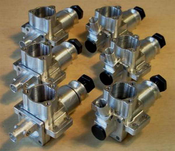
 The crankcase is produced from 1.75 inch (45mm) square bar using a 4-jaw chuck. This can be either self centering or have independent jaws. The self centering type is easier to use—the crankshaft centerline offset is set by the application of packing pieces (one 0.125"—two 0.062" or to suit desired offset for the applied bar stock). Using this method batch production is possible. You will need to make a minimum of 3 crankcases should you intend to complete the entire development program of Reed, Drum and Disc induction versions of the engine. The required crankshafts are different and it is not a good idea to repeatedly change shafts and bearings in the same crankcase.
Having machined the block square and to length, a pilot hole 0.25" diameter is drilled and reamed through it. This is used to guide and locate the special reamer spigots. Subsequently, this hole is opened up by a 'D' bit to 0.251" diameter providing running clearance for the crankshaft.

A limiting feature of the design is that there is no simple means to machine the front bearing housing (there is no backplate screw thread to retain the case on a headstock spigot for multiple production). The procedure I have adopted is to machine the front bearing housing as the first rather than as the second operation. It does not matter whether production is from bar stock or casting. After machining the front bearing cavity, the outer diameter of the front bearing housing is also machined, just as it was on the original die castings. The crankcase can then be reversed and gripped on the machined diameter in a 5C collet chuck to machine the inner bearing housing from the opposite end. The collet used has been ground internally. This was achieved using my toolpost grinder to ensure concentricity and alignment. If you do not have grinding facility then obtain an "emergency" 5C collet from your local supplier and bore this in situ. A set of soft jaws for your chuck is an alternative, however this may not be as satisfactory.

Whilst subsequent operations can be carried out by the application of an angle plate, spigot and faceplate, it is probably better to make a universal fixture. This should be capable of mounting on the lathe, rotary table or milling machine. By changing the fixture spigot, items other than the crankcase can be held for additional operations. The universal fixture has been demonstrated at recent model engineering exhibitions. Castings for this could be made available on request.
Machining both inside and outside surfaces can be achieved by manual or CNC process. It is easier to produce complex shapes using small diameter cutters by the latter method. The problem of cutting speed and sensitivity is under control avoiding breakages.
 |
 |
 |


This page designed to look best when using anything but IE!
Please submit all questions and comments to
[email protected]