| Unless otherwise expressed, all original text, drawings, and photographs on this page created by Gordon Cornell are licensed under a Creative Commons Attribution-Noncommercial-Share Alike 3.0 License. |

|
Model Engine Development
Part 4

Introduction to the Disc Valve

My first experience of the disc valve engine occurred when I purchased an ED Bee following my first week at work, age 16, in September 1948. This cost me my full weeks pay and my mother's reaction was, "were is my share?" It just shows how immature I must have been having just left Wimbledon Technical College with a 1st Class Diploma (like ONC). It was some ten years later and without any design and development experience of disc valves that I determined that such a system should be constructed.
")
The most powerful engines up to that time had featured disc valve induction with record speeds being set by engines such as the McCoy 60 (10 cc) On a small 1.5 cc capacity engine, it is difficult to achieve an adequate gas flow due to the limited diameter of the crankcase bore which restricts the diameter of the intake port. Testing of the drum valve system had shown little improvement over the original reed induction. So research rather than development was required to investigate the unsatisfactory output of the Fury. Unfortunately I did not have the ICE program to guide me; just my chart. Performance of the disc prototype was only marginally better than the reed and comparable to the drum. It was however more compact, lighter, and was easy to modify by cut and try, so it appeared the best compromise for further development
Just how well a disc system will perform depends on the wear rate and friction loss. Eccentric loads from the crankpin must not be transmitted to the disc as such forces can cause rapid wear and catastrophic failures of both disc and conrod. My evaluation at that time was that the disc could be mounted on a pin which revolved in the backplate. The length of the bearing would thus be greater, increasing disc life. Such a system would also permit a smaller diameter pin to be applied, however I did not explore this idea in greater depth.
High rates of wear occur when the disc pivots on a fixed pin. In some cases, a ball bearing has been fitted to the disc to improve life, however this is costly and complex. The disc itself could be made in plastic by injection moulding and it did not have to be retained by a shoulder on the pin as was used for the ED Racer, Bee, Hornet, etc. This implied that frictional losses would be reduced because surface pressure would only be applied during the scavenge phase, hence the precise timing would not be critical. The disc would lift off its seat during the induction phase in a similar fashion to a reed valve. Because the backplate was fixed by four bolts in a square pattern, it was also decided to introduce a second drive hole in the valve at 90 degrees allowing the jet to be assembled either horizontally or vertically. Rotating the assembly 180 degrees permitted the engine to run in the opposite direction. This would increase the sales potential of such a motor.
A limitation of the rear disc induction engine is that damage to the disc can occur due to a frontal impact. To minimize this risk, crankshaft end float must be limited—there must be no significant clearance between the propeller driver and the front ball bearing. Shim washers should be fitted to prevent the crankpin jamming against the disc.

The reason for selecting plastic was that aluminium discs and backplates suffer from friction welding and metal particles can damage the piston cylinder fit. My first prototypes utilized Tufnol with a pressed in pin. The first production items made in-house using bakelite were a disaster. The pin frequently was not true to the sealing surface and it would have been quite expensive as an injection moulding in nylon. Impact damage occurred when models using these crashed because crankshaft end float was not limited. My later contest motors reverted to the pivot pin system as per other ED engines even though wear rates of the disc pivot pin hole can be excessive with this arrangement. Drawings of the replica style system is of that type and constructors should evaluate their preference. The floating arrangement has the merit of longer life, easy replacement and modification. The reduced diameter, integrated pivot pin is still worthy of further investigation, however a revised backplate would be required. This could feature separate choke tubes and/or a peripheral jet system.
The Mk2 Super Fury produced in 1970 applied such a disc as per my original plan. However an error was made in the design of the backplate restricting the jet to vertical assembly only. The 1970 nylon backplate choke has a larger choke diameter and whilst this may provide higher power output, fuel consumption may be excessive for racing purposes. Spares for these parts are still available at this time. My first replicas were fitted with the production nylon disc which is nicely made and can be fitted to either the original pressure die cast, or replica backplate. This may be more durable than Tufnol which can be brittle (now substituted by green low friction nylon). A press fitted or riveted pin can also be applied with other material options for the disc. A riveted pin would by nature have to be soft and malleable. The probability exists that the nylon backplate could be modified to take a threaded choke to reduce the diameter and permit all of the original options regarding jet position, as well as reversed crankshaft rotation.
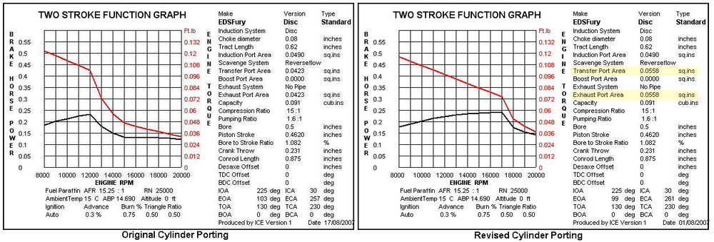
At the time without my ICE program I was not immediately aware of the porting defects. The BHP curves shown for this version show the potential difference between the original Fury cylinder and that developed subsequently. These illustrate the importance of the relationship between exhaust, scavenge and induction. The curves indicate a distinctive cut off point due to inadequate porting. This does not take into account the effect of sub piston induction which was added during the later development. This would extend these curves providing an output close to that of my team race motor tested by Peter Chinn in June 1962.
The induction timing can be modified to close 50 degrees ATDC without sub piston induction. This is achieved by modifying the venturi port period. A BHP curve showing this development combined with the cylinder porting modifications is shown in Part 5.
Currently, Drum Valve induction is the preferred option for team racing engines despite the cost and weight penalty incurred. However, readers should not be discouraged by the problems and limitations indicated here for the disc valve engine. This is all part of the research and development process and solutions to the defects lead to better products. We all learn from the errors we make, so get to work on your ideas. We could review these later; the purpose behind this series being to encourage participation.
Making a Disc Replica
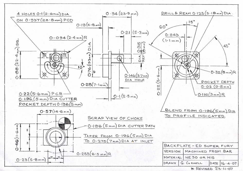
The drawing represents a close replica of the standard pressure die-cast backplate. The original had a choke diameter of 0.21 inches. To reduce fuel consumption for racing purposes, a choke of 0.190 inch diameter was fitted. For the replica backplate, this is 5mm (0.196) diameter. A socket screw is fitted through this to secure the backplate for milling operations. A wider range of options would be available if the backplate was modified to take a separate, threaded choke. A peripheral jet system could be also be adopted. The limitation of this system would be in providing the smoothest possible inlet tract. Under normal circumstances with rotary induction, differential pressure rarely exceeds 2 PSI, so flow inboard of the jet can be super critical.
Readers should consider alternatives bearing in mind the proximity of the backplate fixing screws and location of the disc pivot pin drilling (the choke locknut must not foul the backplate screws). The engine was intended to be a mass produced item with racing potential, so the drawings represent the least expensive option. Racing engines are usually rapidly out dated.—however the Mk 2 Super Fury when produced in 1970 some ten years later was stated by Peter Chinn as being the most powerful production 1.5cc diesel engine.

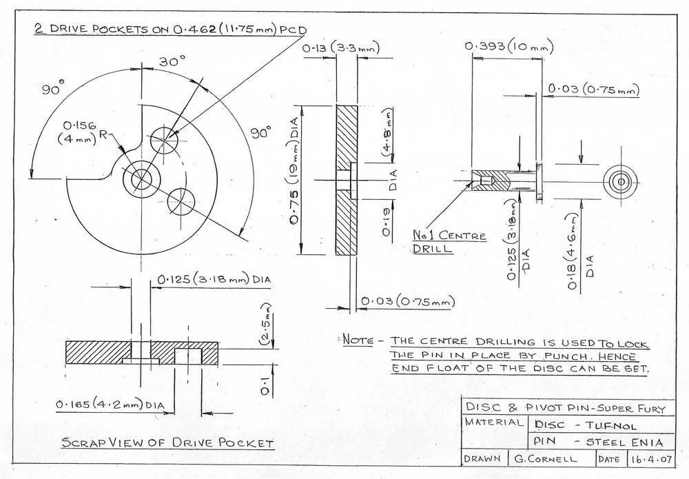
The replica backplate including the choke is produced from bar stock, the choke dimensions are restricted by the diameter of the crankcase bore and crank throw. It is important to ensure that the backplate is a close fit in the crankcase. This is required to ensure that the disc pivot pin is concentric with the crankshaft. The fixing screws must not displace this when assembled as such an error can lead to disc failure. The disc pivot pin is locked in place by punch expanding the end which passes through the hole in the backplate. This procedure is used to adjust end float of the disc. The intake aperture bore is modified from 5 mm diameter to the form shown on the drawing using a Dremel tool or Swiss file. This provides a larger intake area with an improved orifice coefficient. Sharp edges or abrupt direction changes must be avoided with such a short inlet tract. Timing can be modified to suit the cylinder porting and/or whether sub-piston induction is used. Note that engines built with sub-piston induction may not function as well when silencers or throttles are fitted and that porting modifications may also be required.
 |
 |
 |
 |
My replica components were made by CNC process but the tool paths shown can be applied using appropriate manual methods. Some manufacturers have chrome plated disc and backplate surfaces, but this is not always a good idea. Needless to say, the cylinders were wrecked by chrome particles and I have had to make Tufnol disc replacements. If you decide to develop a system based upon plastic such as the Mk 2 Super Fury, it is important to establish that this is compatible with the applied fuel. The production spares of this type are only suitable for use with model diesel fuel mixtures

Whilst the disc drawing states Tufnol as the material I have experienced failures due to inaccurate machining, and/or unsuitable grade of this material. Sheet material is probably better than bar stock (the drive hole can break into the port aperture). Tufnol is expensive so I have changed this to low friction green nylon for my pilot engines. This can cope better with any excess loading.
No concession to disk balancing is necessary. As the disc material is light and its angular velocity is relatively low comparied to a full size engine, then the out of balance forces are low when compared to the paddling load of the disc. The conrod is subject to fore and aft loading when passing through BDC so adding a balance cut-out may exacerbate this sort of problem. But if you believe disc balancing to be significant, make both and prove it—that is just what this project is all about. The most important factor regarding disc durability is to avoid superimposed eccentricity loading from the crankpin.
Prior to assembly, the disc should be flattened on a surface plate with a piece of wet and dry. The back-plate should also be treated in a similar manner, with some oil on the paper. The disc pivot pin is punch locked using a 3 mm ball ended punch. This should only expand the rear end of the pin slightly. The pin itself should be a light press fit in the back-plate. When first assembled there should be no significant disc end float—it should be possible to rotate the disc without excessive torque. Once assembled, any small errors in flatness quickly bed in. What must be avoided is a high centre point.
The plastic backplates from the 1970 series Super Fury can be fitted but this is not true vintage. The plastic disc is satisfactory, however better mixture control and starting is apparent with the system shown on the drawings. Those that wish to conduct experiments with throttle control can do so by purchasing the backplate providing that option. Note the plastic backplates require a different jet assembly.
Details of the needle valve and spraybar assembly are shown in Part 7.


This page designed to look best when using anything but IE!
Please submit all questions and comments to
[email protected]