PAL 55
 |
| Name | PAL 55 | Designer | Paul A Lebeda |
| Bore | 0.750" | Stroke | 0.625" |
| Type | spark/glow in-line twin |
Capacity | .276 cuin x 2 (.552 cuin total) |
| Production run | 25 | Country of Origin | USA |
| Photo by | Tim Dannels | Year of manufacture | 1950 |
Background
For the essential background to this engine please read Model Engine And Designer And Manufacturer Profiles #37 [1], by the late David R Janson. It's significant, so we'll wait while you go read it.
Done? At the end of his (undated) review, Janson asks "Has anyone ever seen one away from his shop?", and infers the engines, although advertised, never went beyond the prototype stage. Anderson's Blue Book [2] lists three distinct PAL 55 models, suggesting at least 25 were manufactured. Tim Dannels' American Model Engine Encyclopedia [3] agrees with [2] on the models and numbers manufactured, although there is a variation in the year of manufacture, and notes that "No complete engines are known to exist in any collections".
 |
 |
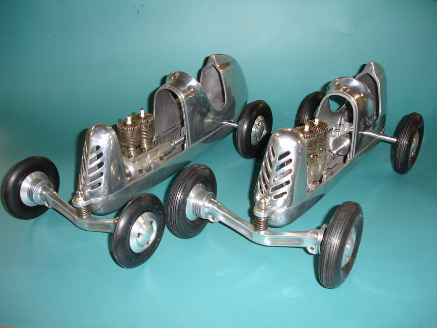
The Janson review references The Engine Collectors' Journal (ECJ), Issue #41, March-April, 1972, by Dick Dwyer [4]. ECJ revisited the PAL 55 almost thirty-three years later, in Issue #191, January, 2009 [5]. The new article, by ECJ Editor, Tim Dannels, includes photos of original PAL 55's installed in tether cars, the castings for which are of current manufacture by Dick Cuervorst (Bettendorf, IA, USA). The models are the work Francis C Lebeda, son of the PAL 55's designer, Paul A Lebeda. Tim kindly provided photos sent to him by Lebeda Jr, which we see here.
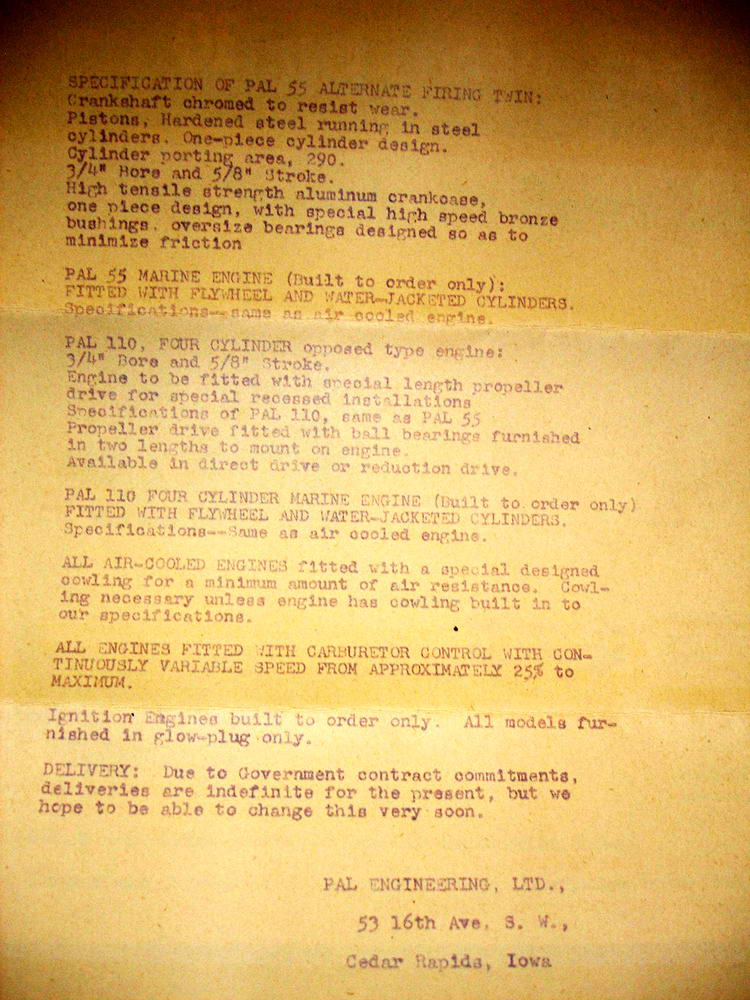
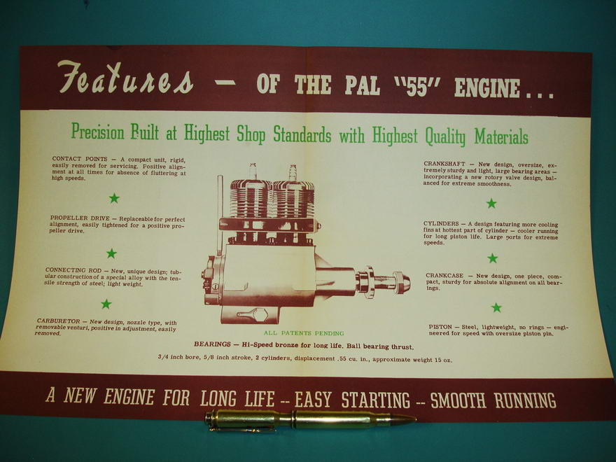
This document, sadly undated, describing the PAL 55 notes that spark ignition is by special order and that all models are normally supplied as glow-plug only. Also available on special order is a water-cooled marine version (featured in [5]) and the curious warning that "deliveries are indefinite for the present". No wonder David Janson assumed they did not exist outside of the factory.
Construction
 |
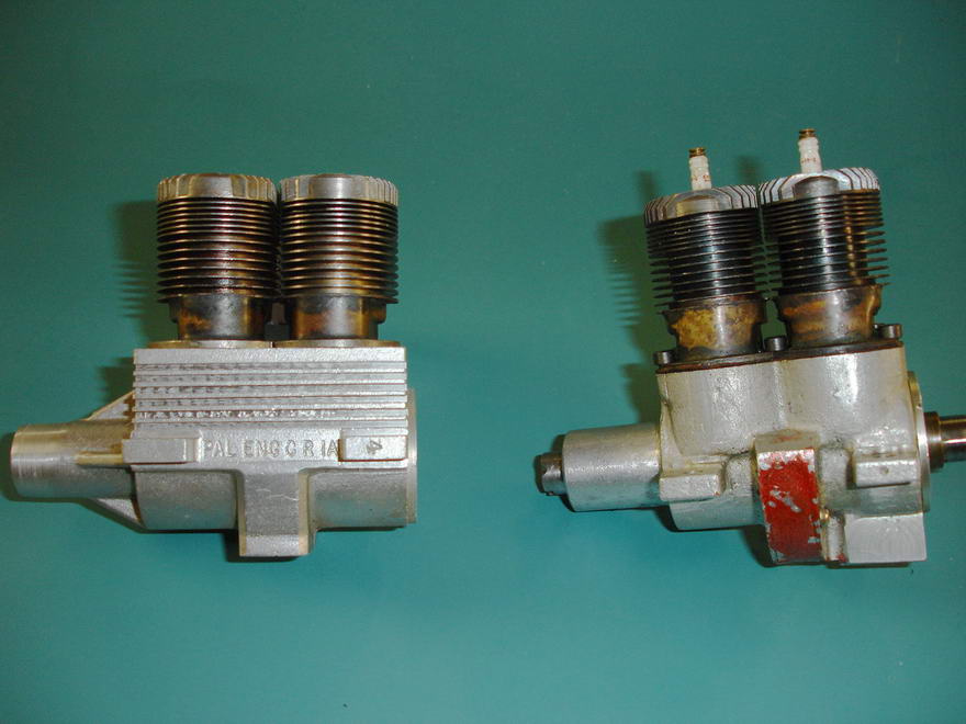 |
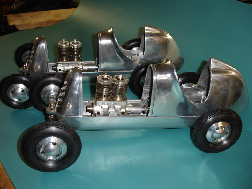
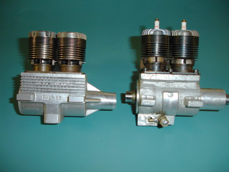
The two incomplete engines seen here represent the extremes of development, supporting David Janson's conclusion that the engines were essentially experimental prototypes. As advertised in Model Airplane News, March, 1950 (see [1]), the engine used spark ignition. References [2] and [3] agree that five of these were made. The engine on the right in the above photos appears similar to the glow plug version, which [2] and [3] estimate that twenty were made. The engine on the left is believed to be a later, experimental design. Both use sand cast crankcases with the two cylinders attached by six cap head screws; the abutting edges of the cylinder flanges being milled away so the center pair of screws clamp both cylinders.
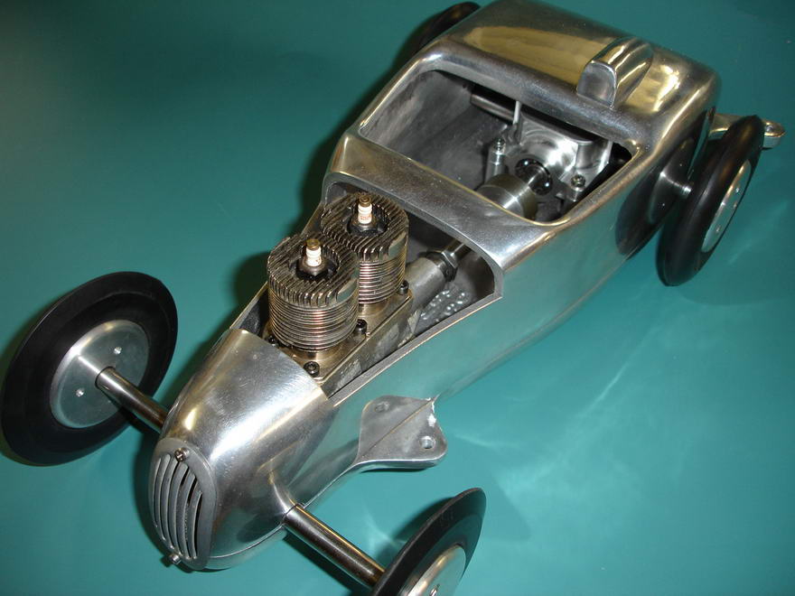
The cylinders are of conventional construction for US spark ignition engines of the 1940's, featuring brazed on bypass covers, and a separate, machined head. The method by which the head was fitted is not obvious. It may have been "staked" on (a technique used by O&R and others), or used a thread, shrunk on before the fins were machined. It is not possible to determine the material used from the photos, though aluminum is the likely choice.
 |
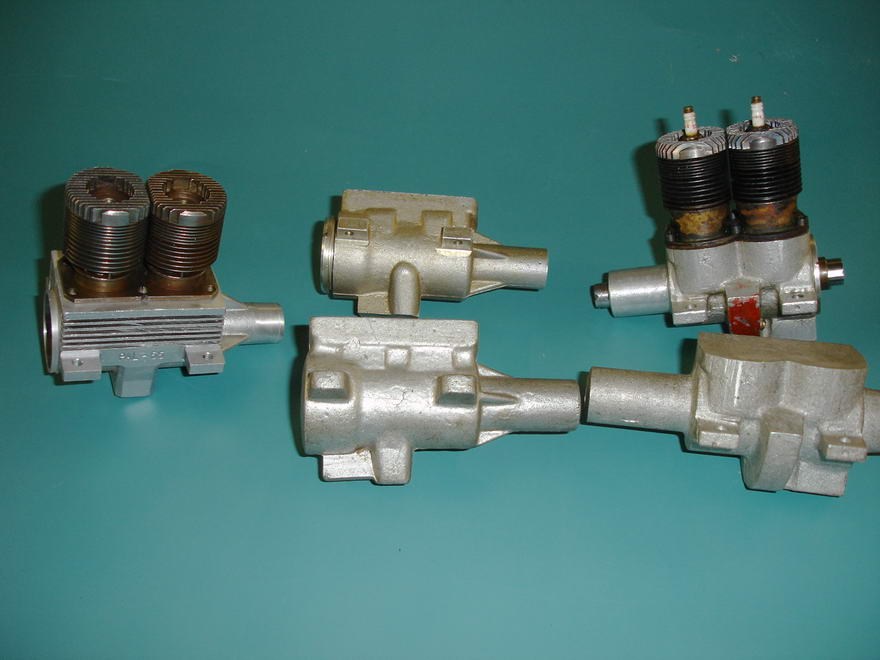 |
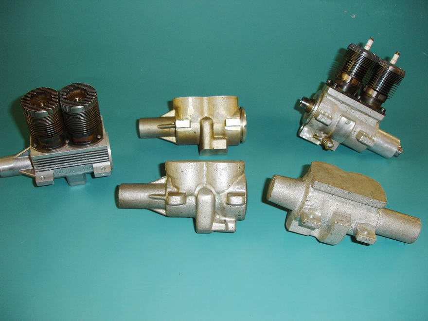
These photos show additional sand cast cases, two at least partially machined, and one "raw", evidenced by the machining spud projecting from the rear. All appear to exhibit minor differences on a basic theme. This is the separate mounting lugs, a dorsal protuberance which forms the air intake, and a raised band occupying approximately 90° of the section between the cylinders. The un-machined case would appear to be the same as that used by the early, almost complete engine on the right. We'll return to the very good reason for that bulge around the mid-section later.
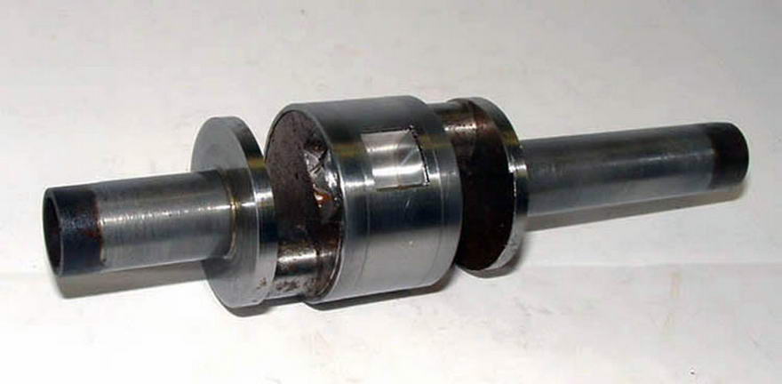
This PAL 55 crankshaft (photo provided by Ward Hallenberg) exhibits rather fine machining and confirms that the engine used the central portion of the crankshaft as a rotary inlet valve to alternately feed the front and rear crankcase chambers. Also evident are the substantial journal diameters used. The con rods would require big end caps of some description in order to assemble the engine. Straps such as those used on by Dan Calkin on his Elves would seem impractical as it would not be possible to fit them with the 'shaft in the case. Westbury type straps would be unlikely for the same reason. This leaves us with a split big end with screws inserted from above. This arrangement, coupled with the large crankpin diameters, suggests that the crankcase needed substantial channels to accommodate the rods, although this is not evident.
Patents
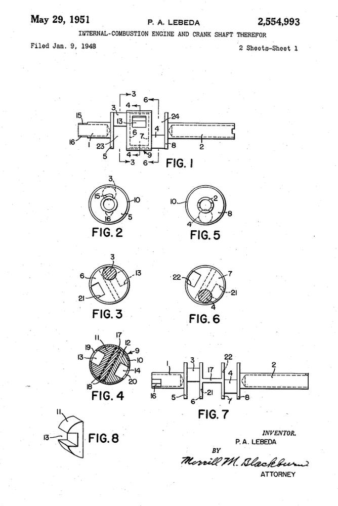
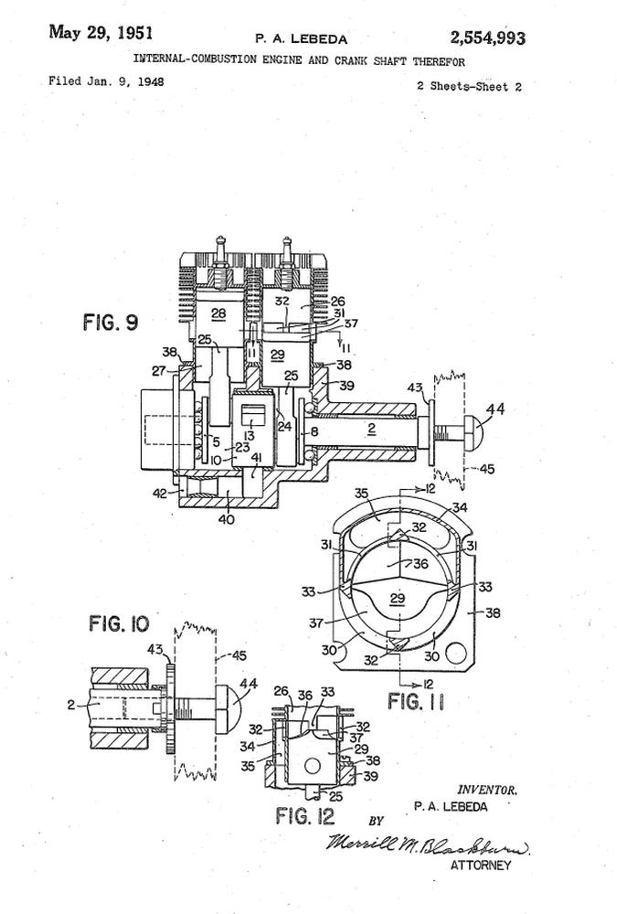
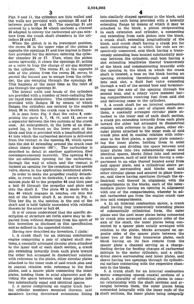
The design of the crankshaft becomes evident when one sees the first of two patents filed by Mr Lebeda. His 1948 patent discloses his solution to the delicate machining of the twin, opposed rotary valves in the center of his one-piece, two-throw crankshaft. As should be self evident from the patent drawings, this is quite ingenious. To save you some tedious reading, flats are milled either side of the central section of the shaft, leaving two crank webs (5 & 8), joined by a flat web (17). Light alloy sections (11 & 12, and Fig 8) drop into the two recesses, sitting on rubber pads (18), which compress when the outer band (9) is shrunk over the central section. This band contains ports (19 & 20) which register with the channels (13) in the wedges. Presumably, the band is oversize in diameter, allowing the completed assembly to go back in the lathe between centers to be turned true and to size for the central crankshaft journal bearing.
 |
 |
 |
 |
 |
US Patent #2554993A
Although Lebeda's crankshaft construction appears to be unique, the use of a crankweb sized central spool in a twin cylinder alternate firing, crankcase-charged two-stroke is not. The down side is additional friction from the large bearing surface, and the precision required to keep everything concentric, free, and gas-tight. There is another problem, but let's leave that until we look at Paul Lebeda's next patent.
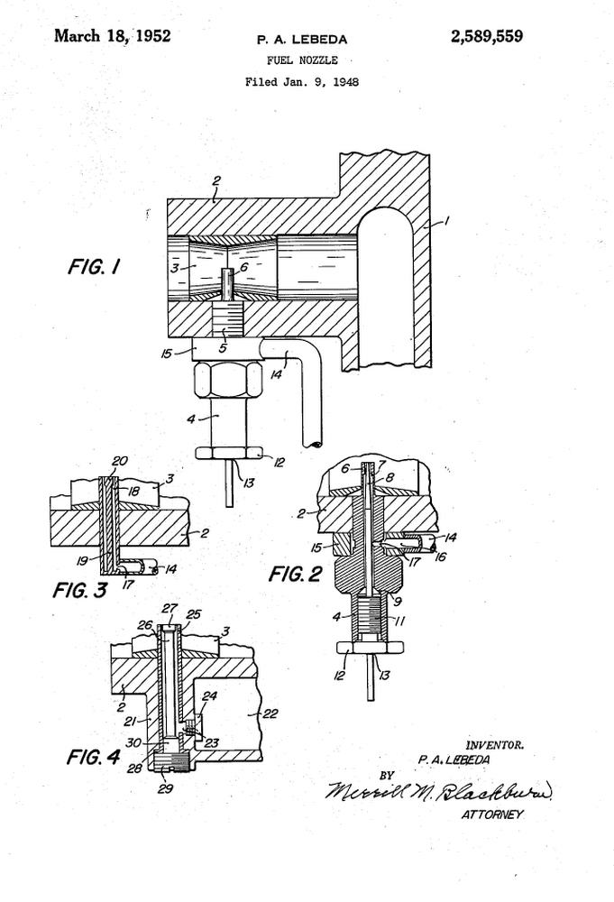
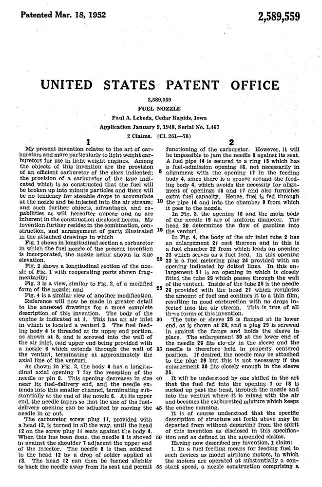
Mr Lededa's 1952 patent applies to his carburetor. While the application of his other patent to the PAL 55 is quite evident, this is less so. But then, the patent (45) does state that:
 |
 |
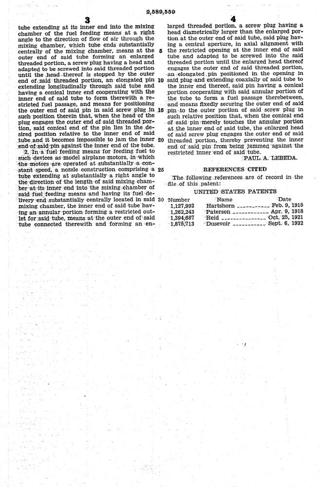 |
US Patent #2589559A
The wording of all patents is intentionally convoluted. I don't know about you, but to me, this one leaves convoluted in the dust, extending well into the impenetrable! I also don't see much in the diagrams that is new and unique, though there is one interesting aspect which gets no mention: looking to the right of the venturi passage in Fig 1, we see a it connects to a vertical passage. Now I wonder what that is...
Back to the Bulge
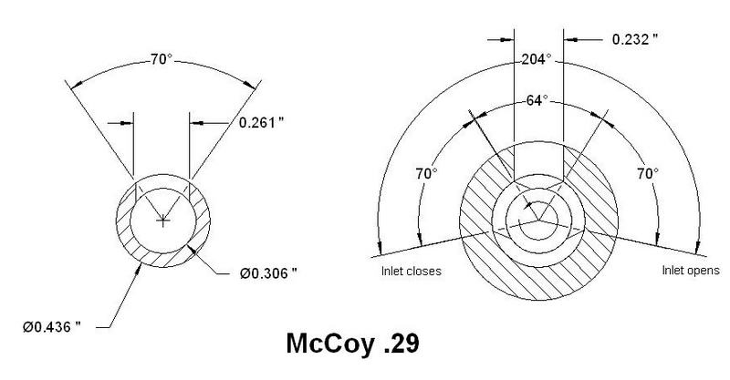
Earlier, we mentioned that there was another problem associated with the large journal between the crankpins being used as a shaft-rotary valve. This is due to the fact that the inlet hole forms a much smaller "pie segment" on a large diameter than the same hole size would have on a smaller, conventional shaft journal. And why does this matter? Well, the inlet opening duration is effectively the sum of the included angle of three pieces of pie: the shaft opening segment angle, the inlet opening angle, and the shaft opening again. On your typical shaft rotary valve engine, we want somewhere around 160 to 200 degrees of inlet duration.
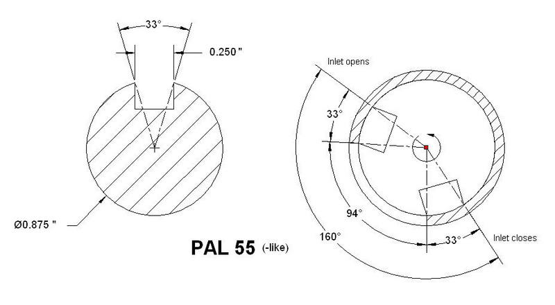
Let's make a couple of guesses and say that the center journal diameter is 7/8" and the inlet port is 1/4" wide (I think the journal may be larger than that, but we'll be conservative). This means the arc formed by the inlet opening is a bit over 33° wide. Twice that is 66° so our "venturi" opening needs to be 94° wide to reach the minimum we'd like for the inlet duration. By now, light bulbs should be popping on as you say, Ah-ah! So that's the reason for that crescent bulge we see around the center of the crankcase! It's a plenum chamber filled by the venturi, wide enough, radialy speaking, to provide the required inlet duration.
Ok, I've simplified that a bit and ignored a detail or two, but the picture as painted is close enough for government work. On the practical side, how the devil did he machine out the quadrant on the inside of the case under that external bulge!? EDM would do it, but I doubt that was used. Rocking the chuck by hand with a boring tool advanced like a shaper might be made to work, provided we could somehow provide blind holes at the start and end of the channel. If it was me, I'd use a thick center bush and rely on the inlet slot milled in that to form the chamber, but then we would not need the case protuberance. I sure would like to physically examine a machined PAL 55 case. For that matter, I'd also like a gander at the "unique design, tubular construction of special alloy with the tensile strength of steel" conrods, especially the presumably split big-ends.
Conclusion
The PAL 55 is a very interesting engine, both historically, and technically. The David Janson review is essentially correct, even if the tone is somewhat more skeptical than is warranted. However some rather extreme claims for the engine were made in print, and it's a bit remarkable that no mention is made of the patents registered by the designer. This in an age when "pat pend" was not an unfamiliar sight on products and advertising when the maker wanted to scare off imitators, so why did the 1950 advertisements not make mention of the 1948 patent? As David Janson was fond of saying, only the Shadow knows...
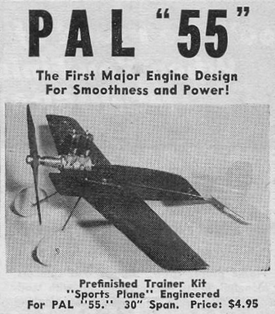
Janson's cynicism over the PAL 55 advertising claims may be as excessive as the claims themselves, but we have to agree with him that the prefinished "PAL 55 sport plane" control line model illustrated in the early advertising is a joke! I for one would not like to be at the other end of the lines when the engine quit—it'd have the glide ratio of an anvil thrown off a roof! So let's ignore that little item and consider just the engine design. Even if, with the possible exception of those installed in car bodies by the designer's son, no complete engines are known to exist in collections, Mr Lebeda's crankshaft is unique and practical, though I think the cost of small scale manufacture would kill his profit margin to users; collectors are all crazy anyway and may have paid a premium. Our sources, both reliable, believe 25 engines were made, so just maybe the PAL 55 deserves a better reputation than it has had to date.
References:
| [1] | http://modelenginenews.org/drj/pal55.html: accessed 2012-06-22. |
| [2] | Anderson, Frank: Anderson's Blue Book, 5th Edition, self-published, Innisfil ON Canada, p 87. |
| [3] | Dannels, Tim, American Model Engine Encyclopedia, Country View Enterprises, Buena Vista CO USA, 2005, p204. |
| [4] | Dwyer, Dick, The Engine Collectors' Journal, Volume 8, Number 5, Issue 41, The Model Museum, Yates CO USA, 1972. |
| [5] | Dannels, Tim, The Engine Collectors' Journal, Volume 33, Number 5, Issue 191, The Model Museum, Buena Vista CO USA, 2009, ISSN 1066-7172. |
![]()
