 (Dan Calkin never called them Elves)
Click on a photo to view it full sized. Click on a label to read about the photo.
People either seem to love or hate the "Elf" range of engines that were produced by Dan Calkin of Portland, Oregon. These were made during the years from the Great Depression Era of the 1930's, through to the early 1950's, spanning the ignition and glow plug era. The Elf series incorporated many innovative features (whether for good or evil, I leave to the beholder). One noteworthy feature was the modular construction. This permitted Dan and his wife and occasional helpers to produce not only single cylinder engines, but two, four and six cylinder engines from common sub assemblies.
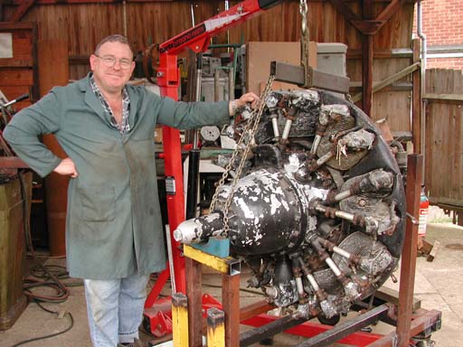
Some years back, noted English engine builder Ken Croft introduced me to Eric Offen--that's Eric with one of his less ambitious restoration projects at the top of this page. Eric is another UK IC engine fanatic, and I use the word in the most respectful sense! Both he and I are in the "love them" camp regarding Elfs and for some time, Eric has been making a batch of Elfs from Art DeKlab's castings. Not one to tackle simple projects, he set out to build at least one of just about everything Dan made, and two of some. Occasional photos of his progress have appeared in the Gallery Page, but as the project approaches a successful completion, I wanted to present his achievement on a page of its own. So, this page is dedicated to Eric Offen and rather than pen more praises for Eric's skill and knowledge, I think I'll let the photographs speak for themselves.


Crankcases
This shows the modular Elf crankcase construction. At either end of the front row are single culinder cases. The one on the right is the first series. This proved prone to crash damage, so subsequent engines carried the webs around the main journal visible on the case on the far left. In between at the front are cases for two cylinder engines. Again the one to the right is an early, un-webbed case. At the rear are 4 and 6 cylinder cases. These use the front and rear halves of the two cylinder engine, with either one, or two extra sections sandwiched in between. The twin and four cylinder engines were produced initally in side port configurations (as was the single). Later, Elf changed to reed valve induction. All 6's were reed valve. The flats visible are for the induction manifold of the reed valve variants.Crankcases and Parts
Here are Eric's parts bins showing some of the castings yet to be machined, with part machined cases in the foreground. The world supply of Elfs is set to increase by nine.Elf 6 Case
An Elf 6 case with cylinder openings machined and attach holes drilled and tapped. The Elfs use 3-44 threads throughout--a thread not that common in model engines today. The lug with the two holes at the rear has a mate on the underside of the case. These are used to mount the engine. The similar undrilled ones at the front will be milled away. They are there because of the commonality of castings (think about it).Oh bother...
Here we see one of the shafts for the 6 which has, in Eric's words, "...popped out for a quick trip round the workshop and came back the worst for it... (sob sob)". I often wonder why things like this happen on the last operation instead of the first? Further validation for The Law Of Perversity Of Inanimate Objects, I suppose...Elf 6 parts
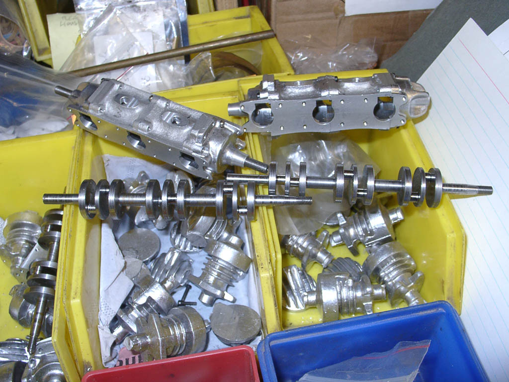
A close up of Elf 6 cases and partially machined shafts. Note that the cases now have openings above the culinder bore for the transfer passages. There is also a 4 cylinder case and shaft visible on the left.Elf 4 parts
PArts for a twin. Early Elfs (series 1 and 2, I think) had fully cast fins on the cylinder jackets. On later engines, the top 3 fins were turned. The unmachined castings here are for that later version.Machining Crank Throws

 Eric has some nice heavy duty machinary. Here is a 5C collet block mounted offset on a faceplate to turn the crankpins on Elf shafts. The pin is fully formed in one plunging cut (probably under power feed if I know Eric). My poor little Myford would not even spin the 5C fitting, let alone form the pin in one cut.
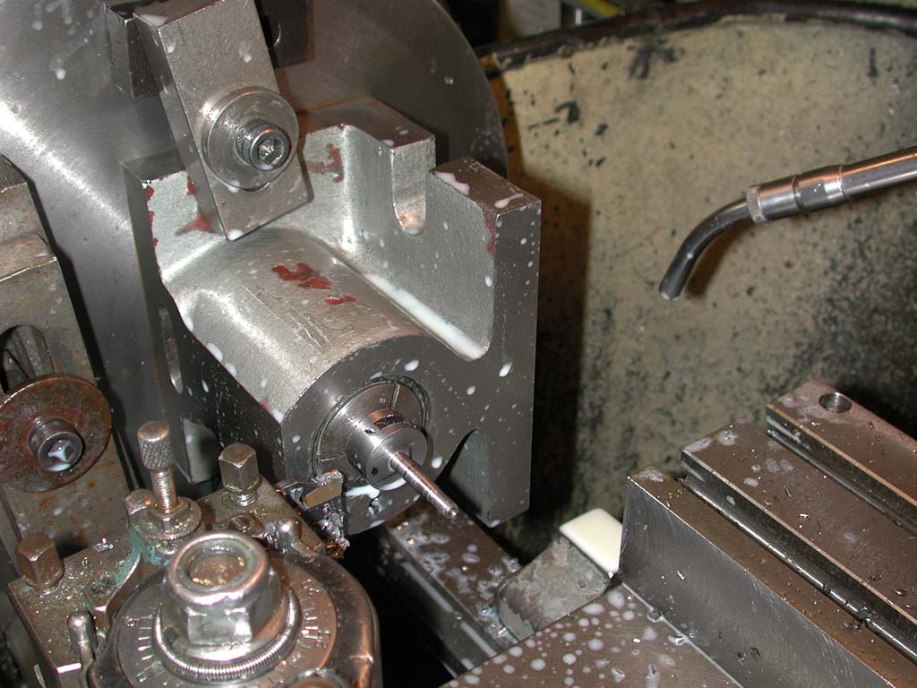
Elf 6 Trial Assembly
A 6 from the exhaust side, and no it's not been anodized purple, that's just a trick of the light. The heads have been fitted, but the exhaust is not drilled through, meaning the bore may not have been machined. Visible in the troughs of the case are the 8 screws that secure the two center case segments (quadrents?) together either side of the crankshaft. If Eric's anything like me, this was done just to admire it as much as to test the fits. I then have a tendency to carry it around the house with me for the next few hours to continue the admiration session.Head Relief
The Elfs are called "slant plug" engines due to the, well, slanting arrangement of the spark (or glow) plug! On the multi cylinder engines, there is not enough room between cylinders to facilitate insertion and removal of the plugs, so the forward face of the aft cylinder heads must be milled away as shown here to provide clearance.Finished Heads
This view, from the spark plug side, shows the four counter bored head attach screw holes, with cylinders in the background awaiting fin cutting.Head Periphery Before
Here a head is pushed against a stub in a 5C collet by a pressure pad in the tailstock to trim the outside of the head casting to finished size.Head Periphery After
Here is the head after completion of the operation.Head set-up
Yet another view of the same setup. Just gotta get me a 5C nose for the Myford.Another Trial Assembly
In this shot, the bifurcating transfer holes that lead to the front and rear reed valve pairs can be seen. Eric says that final assembly of a 6 takes about 3 hours, getting all the case component faces flat while making sure all the reeds are not bent, then fitting the reed retainer screws.Rods...
The Elf rod is very unusual. What we see here are actually pairs of rods before they are separated. As the crankshaft is one piece, the big end of the rods needs to be split some way for assembly. Dan Calkin used a phos bronze strap that clipped into tiny ridges on either side of the rod. Many see this as a weakness--in fact a recent Elf Reproduction by Arne Hende uses "full size" practice of screwing the two halves together. However, the original Elfs had a parallel bore and comparatively low compression, so the rod was always under compression and stresses on the strap were low.Rods...
Another view of the uncut rods. I'm guessing that the profile on the little end has been formed with a semicircular milling cutter with a whole stack of blanks screwed together. The fully little ears left when the round section was turned will later be trimmed away....and more Rods
Here is a rod blank in a fixture having the shaft turned by a tool that also profiles the transition at each end. If you look closely at the small screw holding the blank in the fixture, you can see how half its head has been milled away when the outer perimeter of the little end was formed. The remaining diameter hides the top of the little end from view. The fixture is neatly milled into the a piece of bar stock to bring the center of the rod blank into the lathe axis.Rod in Fixture
A closer view of the last operation. A center has been drilled for the tailstock support and will serve as an oil hole in the finished rod. You can also see the different profiles on the tool for either end, and how how the screw securing the rod through the big end hole is also being neatly profiled.Cylinder Liners
The Elf used thin wall steel liners, pressed into the aluminum jackets. Calkin punched the ports into this tube. Eric was unable to locate suitable tube, so he ended up macjining the liners from bar stock. Elfs used various arrangements of holes and slots for ports. This lot uses slots.Thrust Bearings
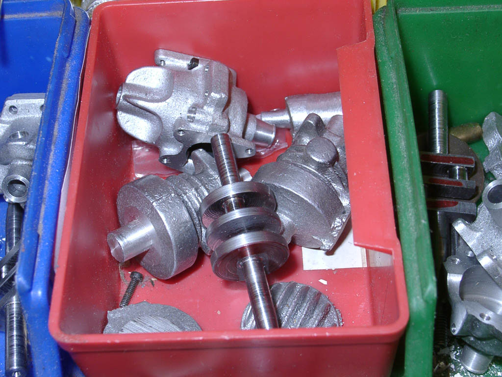
All Dan Calkin's Elfs had ball thrust bearings at the front of the case (these could be moved to the back of the case for pusher installations). This shot shows the ball carriers--note the one on the right has a ball installed at the 11 o'clock position. The balls snap into the holes and run between thin, hardened steel washers not shown in this picture. Also notice the pair of reeds that have been slipped over the shaft. They are secured by a screw at the bottom of the case, sealing the inlet at top of the case. This design replaced the side port induction on all later Elfs.Reeds
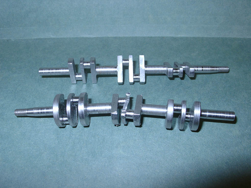
This shows the shape of the reeds in better detail, along with the thrust bearing carriers and a crankshaft.Milling the Shaft Webs
Here the center crank webs are milled away either side of the opposing crank pins. This is the "oh bother" operation being repeated. I would have been a trifle apprehensive during this operation...Finished Shafts
Time to remove heart from mouth and take something for the shakes. All webs machined and shafts ready to install.Cases and Shaft
In this shot, the shafts are assembed in their cases and posed on top of the drawings supplied with Art's kits. There are six individual faces that make up the cylinder mounting flange which must be flat to ensure a good seal. You can just spot the joins in the cylinder openings on the top case's trial assembly; the bottom joins are just about invisible.Cases and Shaft closeup
This closeup shows the lateral and longitudinal segment joins. If you look closely, there is a lateral join to the front of center at each cylinder opening on this side (staggering of the cylinders places it at the rear on the other side). The center segments of the case are split top/bottom and screwed together allowing the shaft to be inserted. These segments act as (unbushed) intermediate shaft journals.Exploded View
All the case segments, fully assembled shaft with rods and thrust bearing are neatly posed here. Note the four reeds: one each to supply the front and rear cylinder pairs and two to supply the center pair. The rear washer of the thrust race is visible on the front of the crankshaft and the way the case segments join laterally is clearly visible.Rod Strap Closeup
This shows the phospher bronze straps that retain the con rods clearly. As mentioned earlier, as the cylinder bores are parallel, the rod *should* always be under positive pressure onto the big end, so the straps carry no load. Note the neat way the strap "T" ends fair into the rod profile to occupy a minimum of space within the tiny crankcase.Assembled Shaft
Nothing to say... just admire it.Assembled Cases
Looking like a pair long boats with sloppy oarsmanship, are two six's ready for their cylinders. Notice that the ears have been removed from the little end of the rods. The "center" at the top of each rod used to support the rods during turning that now forms an oil hole is visible on the front rods.Completed Elf 6
At last! A fully assembled Elf Six. The shaft stub at the rear carried the timer and distributor assemblies on the ignition engines, but as far as I'm aware, the 6 was only ever produced as a glow plug engine, so here it sits idle for effect.Completed Elf 6 (Underside)
Worth noting in the photos showing the underside of the Elf 6 are the little pointed thingies. These are screws that retain the reed valves. Eric reports they are a lot of fun to fit--but one thing shared by the English and Australians is a very dry wit and a tendency towards gross understatement!.
![]()
This page designed to look best when using anything but IE!
Please submit all questions and comments to [email protected]