The ED Baby
Reproduction Project
Page 4
Created: October 2008
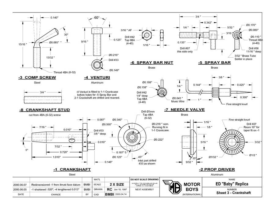
Sheet 3 gives details of the crankshaft, needle valve assembly (NVA), and some other fiddly bits. You should also refer back to Sheet 5 that appeared with Part 3 of this series for details of the jigs and fixtures required for the 3-1 Crankshaft and 3-2 Prop Drive Washer. Now down to business...
- Part:
- 3-3 Compression Screw
- Prerequisites:
- 2-2 Cylinder Head
- Things to Watch:
- To prevent the screw wandering under vibration, the thread should be a firm fit in the tapped hole and the center of the screw tip should be hollow.
- Tooling Required:
- Round nosed turning tool, #1CD. If no threaded rod is available you'll also need a 4BA (6-32) adjustable die.
Procedure:
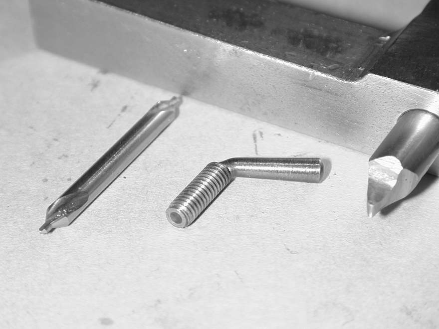
- Cut a length of 4BA (6-32) threaded steel rod 1" long. Place in 3JSC chuck with minimal length protruding, protecting the thread with a shim cut from aluminium drink can (at last! A use for all those empty beer cans!). Face the end cleanly and hollow the tip with a #1CD.
- Reverse in the chuck with 9/16" protruding. Face end and bring to a dome shape with a needle file.
- Set over the compound slide to about 2 to turn narrower at the headstock end. Fit a round nosed tool with a tip radius of about 1/16" and turn down for a total length of 0.53" from the domed end until all the thread has been removed. At this point, the narrowest dimension should be between 0.080" and 0.095".
- While still in the chuck, bend over the bar to at least 70° from the lathe axis. This can be most easily done using a length of bar pre-drilled and internally radiused as a lever. NOTE: If you cannot obtain suitable threaded steel rod, or a long enough machine screw, you will need to tap a length of 0.140"D steel bar. When doing this, open your die to ensure that the screw thread is a close fit in the 2-2 Cylinder Head.
- Polish end, then heat part to deep blue in gas flame, quenching in water and smearing with oil to provide an attractive, blue, anti-rust finish.
- Part:
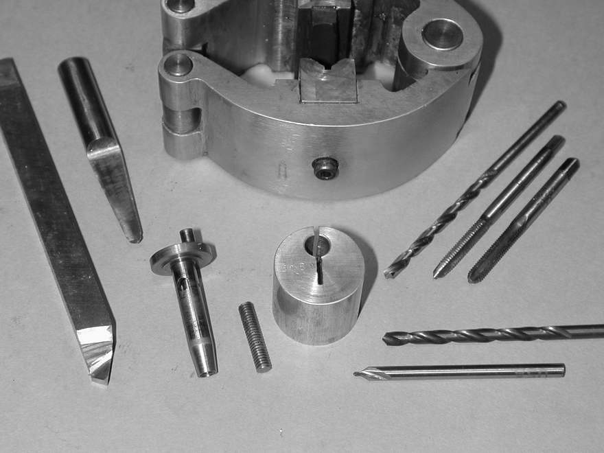
- 3-1 Crankshaft
- Prerequisites:
- 1-1 Crankcase, 2-5 Conrod
- Things to Watch:
- Nil.
- Tooling Required:
- Knife turning tool, 3mm and #33 drills, 4BA (6-32 UNC) taper and bottoming taps, standard and long #1CD, 10 included angle "D" bit reamer (shop made).
Fixture for offset turning of the crank pin:
Face both ends of a piece of 5/8"D aluminium bar to a length of 1". Mount in the 4JI chuck and adjust until it swings exactly 0.375" off center. This can be measured with a plunger type DTI, or by careful measurement with the lathe cross slide. Clamp up and drill #2CD, followed by #7 and #4 drills, then ream 7/32"D. Before removing, clearly scribe the full diameter that intersects the hole and stub centers. Saw along this line, through the hole for about 3/8". File off all burrs with a triangular needle file.
Procedure:
Note: See the Crankshafts How-to page for more hints.
- Chuck a 1-5/16" length of 5/8"D leaded steel in the 3JSC chuck with minimal protrusion. CD#1 and face off end.
- Remove and measure length. Reverse in chuck with about 3/8" protruding. Face down to an overall length of 1.255", then reduce to 0.560"D for at least 1/4".
- Again reverse in chuck, gripping by the last 3/16" of the 0.560"D and support the protruding length with a half dead center, well greased. Turn down to 0.217"D for a length of 1.010", then form the 0.340"D, 0.010" thick thrust face on the front of the web.
- Hone or lap the shaft to give a free running fit in the 1-1 Crankcase. I use an miniature, adjustable, external hone made from a British kit (see references) which is a copy of a Sunin product. Many builders finish crankshafts with 600 or finer glass paper, backed up on a steel rule and wetted with oil. Be sure to clean the shaft before each trial fit.
- Remove the part and grip your 10 "D" bit reamer in the 3JSC chuck. Mount a plunger type DTI on center height, and set over the compound slide so it tracks the taper of the reamer exactly.
- Replace the unfinished shaft as before, using the tailstock center to re-establish alignment. Remove the center and taper the end of the shaft for a length of 0.290", taking fine cuts of more then 0.002" per pass.
- Drill the shaft 3mm for a depth of 7/16", then start tapping with a 4BA (6-32) intermediate tap in the tailstock chuck, turning the 4JSC chuck by hand. This assures accurate initial alignment. Finish tapping using a small,l sensitive tap handle with the part held between soft jaws in the bench vice.
- Reverse the part, gripping lightly and using drink can shim for protection. Scribe a line across the rear face diameter using a sharp tool on center height. Rotate chuck roughly 90° and scribe a much shorter line.
- Cover the shaft with marking blue and slide it into the crankcase with the scribed line horizontal. Place a #33 drill down the venturi with its chisel point oriented left-right until it touches the shaft. Keeping pressure on both drill bit and rear face of the shaft. Rotate the shaft 90 counter-clockwise as viewed from the front. Remove and verify you can see the light scratch made where the center of your venturi meets the shaft.
- Clamp the shaft in a small tool-makers "V" block, using a protractor set at 45° against the scribed diameter so that the line slopes down, left to right, relative to the base of the "V" block. Clamp the block on parallels in the mill vice so that the scribed face is towards you, then use a point in the drill chuck and the cross in the center of the web to align the mill quill left-right. Now position the point in the chuck until it is over the light mark made in the previous step. Replace the point with a long #1CD and center drill the shaft. Follow up with a #33 drill, going no more than 1/8" deep. Carefully de-burr the edges of the hole with a Swiss pattern needle file.
- Push the shaft into the jig, aligning the two scribed lines so that the inlet hole is to the right of the line, viewed with the slit side uppermost. Grip firmly in the 3JSC chuck so that 2 jaws are equally disposed about the slit to give maximum clamping action. For added insurance against the shaft rotating while making the interrupted cut, you can lightly center drill with a #1CD and present a � dead center to this hole.
- Form the crank pin with a sharp knife tool, taking cuts of no more than 0.015" per pass for a length of 0.148". As the pin approaches the 0.125"D, take finer cuts. Stop when the pin feel like it is nearly ready to enter the 2-5 Con Rod big end, then polish with fine (600 or finer) glass paper backed up by a length of flat HSS and generous oil until the rod is a free, but close fit on the pin. Finally, reduce the web by another 0.010" to within about 0.11" of the pin center.
- Remove the shaft from the jig and grip in the 3JSC chuck using normal shim protection. Carefully chamfer any burrs on the rim of the crank web, the drill #1CD, followed by #33 until it intersects the inlet hole. Take care to advance slowly as this hole approaches the break-through point to avoid drill breakage.
- If you wish, you can carefully case harden the pin for longer life, avoiding any warpage of the shaft in the process.
- Part:
- 3-2 Prop Driver
- Prerequisites:
- 3-1 Crankshaft
- Things to Watch:
- Nil.
- Tooling Required:
- Knife turning tool, small "L" shape boring tool with 1/32" tip width, #1CD and #33 drill, 10 included angle "D" bit reamer (shop made), fine straight knurl and special holder comprising a hardened length of 1/4" drill rod in the end of a 3/8" square mild steel bar, Pot Chuck 1/2" ID, 1/16" deep.
Procedure:
Note: See the Prop-drivers How-to page for more hints.

- Place a length of 1/2" aluminium rod in the 3JSC chuck with 3/4" protruding. Face end, then drill with #1CD, followed by a #33 drill to a depth of 3/8".
- Turn down to 0.23"D for 0.165" with knife tool then rebate a groove about 0.012" deep, 1/32" wide at the shoulder with an "L" shaped boring tool set cross-ways.
- Mount the special single pin holder on center height, oriented so the pin faces away from the operator, angles about 2 so the knurl will be deeper at the perimeter. Slide the knurl on and offer up to the work so the side of the knurl contacts the center stub on the work.
- Start the lathe in reverse rotation and press the knurl into the face at about 500 RPM, brushing in kerosene or Kool-Tool to remove the chips. The reverse rotation will prevent the work grabbing the brush. Stop when a clean knurl with well defined edges has been produced.
- Reduce the center post to 0.220"D, cleaning up any marks made on it by the knurl. Clean up the inner groove with the "L" tool where the knurl has mashed the edges. Clean up the outside for a length of 3/16", again to remove the mashed edges. Part off to a length of 0.290".
- Press driver into pot chuck against the knurled face and grip this in the 3JSC so 2 jaws are disposed equally either side of the slit in the pot chuck. Take a facing cut of about 0.005" of the driver to true the rear face, then ream with the 10° included angle "D" bit reamer that was used as a gauge when tapering the front of the crankshaft. Check fit of 3-1 Crankshaft frequently, and stop reaming when the tapered part of the shaft fits nearly all the way into the driver.
- Take a 0.005" cut across the faced end to a diameter of 5/16". Set over the compound slide by 35° and taper the rear of the driver until the inner edge blends with the 5/16" witness mark.
- Part:
- 3-8 Stud
- Prerequisites:
- 3-1 Crankshaft
- Things to Watch:
- Nil.
- Tooling Required:
- Nil.
Procedure:
- Cut from a length of 4BA (6-32) threaded, steel rod, or an appropriate machine screw. Screw a nut onto the rod and face the ends. Unscrewing the nut will remove any burrs.
- Part:
- 3-7 Needle Valve Thimble
- Prerequisites:
- Nil.
- Things to Watch:
- The size of male threads can be controlled by opening out the die in the die holder. With tapped holes, you take what you get, so make these first and adjust the die on the mating part to obtain the degree of fit required. We want a firm fit between the 3-7 Thimble and 3-5 spray bar, so the thimble is made first.
- Tooling Required:
- Zero rake parting tool, chamfering tool, #1CD, fine straight knurling tool (calliper type preferred), Number 57, 54, 47, and 44 drills, 6BA (4-40) bottoming tap.
Procedure:
- Chuck a length of 3/16"D brass rod in the 3JSC chuck leaving a protrusion of about 3/4". CD #1 and support with half dead center in tailstock.
- Skim 0.015" off stock diameter for approx 7/32".
- Fit parting tool and feed in about 0.020" with right side of tool 3/8" from stock end.
- Apply a fine straight knurl in the raised band formed by steps 2 and 3. The knurl should not touch the lower turned sections.
- Remove dead centre and drill #47, followed by #44, 1/4" deep.
- Fit 6BA (4-40 UNC) bottoming tap to drill chuck in tailstock and tap, rotating 3JSC chuck slowly by hand using a tapping fluid.
- Drill #57 followed by #54 to depth of 1/2" from end face (this order avoids getting tapping fluid in 0.055" hole).
- Lightly chamfer end and start of knurled area with 45 tool.
- Part off leaving part 5 to 10 thou oversize; reverse in 3JSC chuck and skim end where parted off and lightly countersink area around exit hole with #1 CD. Finish off with light chamfer using 45° tool.
- Part:
- 3-6 Spray Bar Nut
- Prerequisites:
- Nil.
- Things to Watch:
- Nil.
- Tooling Required:
- Nil.
Procedure:
- Fit commercial brass nut to a short threaded stub gripped in 3JSC chuck, or collet. Face off to 1/16" thickness and chamfer edges at 30°.
- Part:
- 3-5 Spray Bar
- Prerequisites:
- 3-7 Needle Valve Thimble, 3-6 Spray Bar Nut
- Things to Watch:
- Overall size and location of jet hole may need adjustment if 1-1 casting not 3/8" as drawn.
The 3-5 Spray Bar is a non-reversible assembly. Be sure to drill the fuel jet hole in the correct side! - Tooling Required:
- Zero rake parting tool, chamfering tool, #1CD, #67, 57, 54 and 3/32" drills, 6BA (4-40) adjustable die and tailstock die holder.
Procedure:
- Cross-drill a length of 3/16"D brass rod approx 5/8" from one end with a 3/32" drill to approx 1/8" deep.
- Place in 3JSC chuck with minimal protrusion and drill CD #1.
- Extend end 1" beyond chuck and support with "half" dead center in tailstock. Turn to 0.110" diameter to a point 5/64" from center of the cross drilled feed pipe hole.
- Remove center and thread 6BA (4-40) for approx 3/8" from end using a tailstock supported die holder. Begin with die opened out and reduce on subsequent passes to obtain a firm screw fit with the 3-7 Needle Valve Thimble.
- Replace center and reduce diameter to 0.090" in a band 0.135" wide centered 3/16" from the shoulder.
- Reduce the area around the cross-drilled hole by 0.005" for a distance of 1/4". This is to present a nice bright, shiny area for soldering the feed pipe.
- Tin a stub of 3/32" OD brass tube 1/4" long. Remove stock from chuck, insert the tinned tube in cross-drilled hole and sweat into place (see Needle Valve Final Assembly, Note 5, for hints on tinning and sweating).
- Replace in 3JSC chuck, then drill axially #57 to intersect location of feed tube (measure the distance, but you should feel the drill break into the tube). Open out hole to #54 and check for free fit of 0.055" music wire.
- Remove work and check for free path through feed pipe by blowing into the end. Correct if required by drilling further.
- Move work to the drill press vice and hold by solid rod stock. Touch with point of #1CD at center point of the reduced diameter area (nom.3/16" from the shoulder), then cross drill #67 to break into the central hole. This should be in the middle of the reduced diameter area.
- Return to 3JSC check and part off at 3/16" from the shoulder. Reverse and grip lightly by the 0.110" length in the 3JSC, protected by aluminium drink can stock. Face end down to 5/32" long and lightly chamfer end for neat appearance.
- Part:
- N/A - Spray Bar/Needle Valve final assembly
- Prerequisites:
- 3-5, 3-5, 3-7
- Things to Watch:
- The needle will be soldered to its thimble in situ. It is possible to accidentally solder up the spray bar as well. This is bad. Your day will be ruined. The procedure below will minimize the chances of this.
- Tooling Required:
- Art store type wax pencil (or typewriter corrector fluid).
Procedure:
Note: See the Needles How-to page for more hints.
- Form needle from a length of 0.055"D music wire. This can be done off-hand by rotating the wire against a high speed, fine grit sanding disk. The taper need not be conical (ie bullet shape is ok), but is should extend back as indicated. The longer the length of wire used for this process, the more uniform will be the results.
- Polish to a high finish against a Scotch-Brite™ disk or belt and cut off for a total length of 2-1/4".
- Screw the 3-6 nut onto the 3-7 spray bar to a depth approximating that of the 3/8" width of the intake boss on the 1-1 crankcase. Screw on the thimble to within 1 thread of the nut.
- Insert the needle wire until it bottoms. Mark the needle all around with a wax pencil to within 1/16" of the 3-5 thimble. Withdraw the needle and mark the other end of the needle with the pencil leaving a band approx 3/16" wide.
- Tin this area with electrical, 60/40 resin cored solder by creating a good blob of hot solder between the marked areas. The heat will oxidize the waxed areas preventing the solder running outside the marks. While still molten, quickly wipe off all the solder with a cloth (or moistened fingers, if you are very brave). This forms a tinned area where the solder has "wicked" into the wire, but has not increased the effective diameter measurably. The areas beyond the tinned region are now sufficiently oxidized to prevent unwanted wicking of solder and subsequent disaster. Remove any remaining wax pencil residue.
- Reinsert the needle until it bottoms. Heat the thimble end (not the wire) with the soldering iron, or a gas flame until the end of a piece of solder held against the tinned wire will melt (remove the iron/flame when trying for this temperature). The result will be a small, neat circle of solder formed in the lightly countersunk area around the needle.
- Trim protruding wire to 1-1/4" from thimble. De-bur the end, then bend the last 1/4" at 90° to form the handle.
Congratulations! You have now completed all the parts for your ED Baby replica. On the next page, we address final assembly, check-out, and provide some helpful hints on the care and feeding of Baby Diesels.


 Home
Home
This page designed to look best when using anything but IE!
Please submit all questions and comments to
[email protected]