How To Knurl Prop Drivers
![]()
The purpose behind knurling a prop driver is first and foremost to prevent the clamped up prop from slipping under torque. By preventing slipping, we are also preventing the slipping prop from loosening the prop nut, a situation that can lead to a thrown prop and a shaft-run--not a pretty sight.
There are a number of ways to produce prop driver knurls. For some reason, engine builders starting out seem to be mystified and afraid of this task, but it's really easy to produce "professional" results. In fact, many amateur jobs are better than the drivers I've seen on commercial engines.
Knurls Produced by "Shaping"
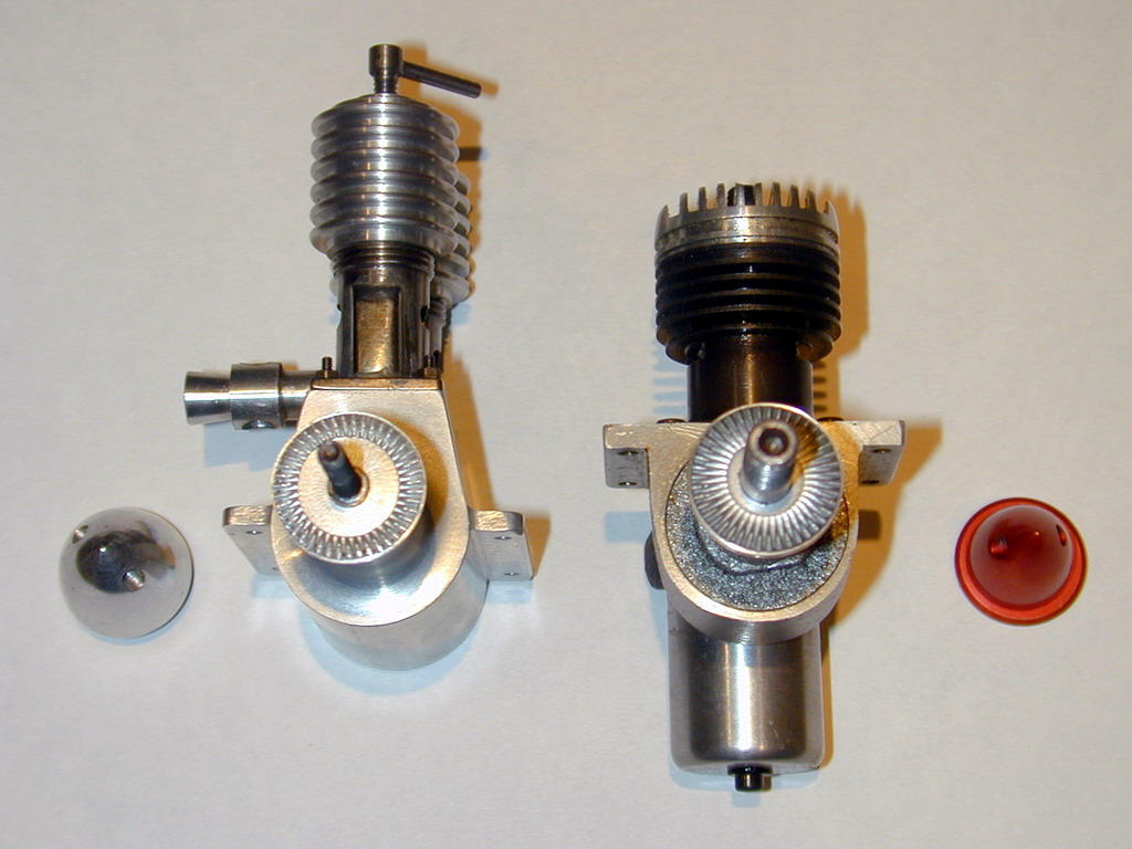
 The first way is a bit crude and very laborious, but can be the better way to go on very small (or very large) drivers. An external thread cutting tool is rotated through 90 degrees, then mounted sideways so it's tip is towards the headstock, and exactly on center height. The saddle is locked, and the cross slide wound in by hand with the spindle held stationary. This forms a V groove on the driver face--much like a shaper would. The driver is then indexed by some number of degrees and the process repeated, and repeated, and repeated, and... you get the picture. The driver shown here for the 0.1cc Nano diesel was made that way.
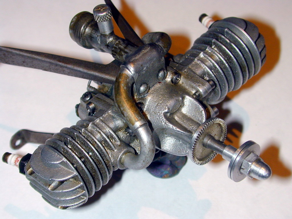
 There's a variation on the "shaper" method that's worth mentioning. Instead of cutting radial grooves, a multy-tooth cutter is ploughed across the face of the driver to produce a series of equally spaced, parallel, chord-wise furrows. This avoids the requirement for a radial groove to taper, which we'll discuss in a minute. One source I read used a broken tap of about 20 TPI that was ground away flat to produce a saw-like edge. The flats were clamped up in a slotted holder (to give the blade some longitudinal strength), and used like a comb. I don't think the result is all that attractive, but it's probably more effective than radial grooves at performing the intended task! The engine pictured here (a Clanford Clan) shows a variation on the technique where a second cut is made at right angles to the first, producing a "flat diamond knurl", if there is such a thing. Again, unusual, and probably quite effective.
The Radial Knurl Problem
Consider the humble, conventional, radial knurl. Because they are radial, the distance between the peaks (and troughs) must become narrower as we approach the center of the driver. If the depth of the knurl were to remain constant, the angle of the V would have to get more acute as we approach the center. This would be very hard to produce, but fortunately, it never happens; the angle stays constant. Hence the depth must vary, becoming shallower as we approach the central axis. We want the face of the driver to be flat, so the troughs must slope up towards the center (otherwise the face would become concave).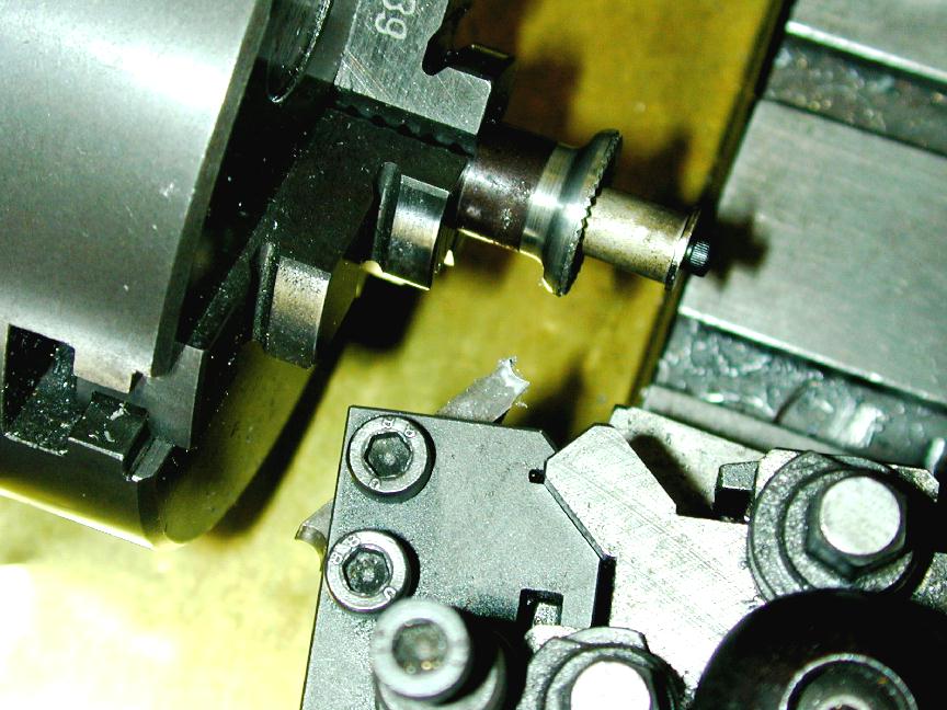
So far, so good, but here's the problem: we want to form radial knurls in a raised band at the edge of the drive washer. Generally, we'll use a standard, straight, fine knurl to form the radial V's. We've determined that the V grooves must be narrower on the inside of the band than on the outside. Since the V's on the knurl are a constant width, the only way we can make them fit into the desired tapered shape is to angle the knurl so that it cuts deeper at the outer edge than at the inner. The actual angle will depend on the number of "teeth" on the knurl, the included angle of the teeth, and the diameters involved. There's no way to predict this without heavy duty math and measurement. But pragmatically, anything between 2 and 5 degrees will do just fine.
Producing Knurls by Plunge Knurling
The most common technique used to produce prop driver knurls, both amateur and commercial, way is by an operation known as "plunge knurling". For this we use a normal knurl in an unusual way. In stead of rolling it around a diameter, we mash it into the flat face of the driver--hence the "plunge knurling" term.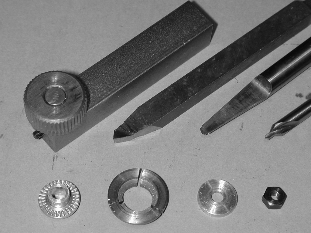
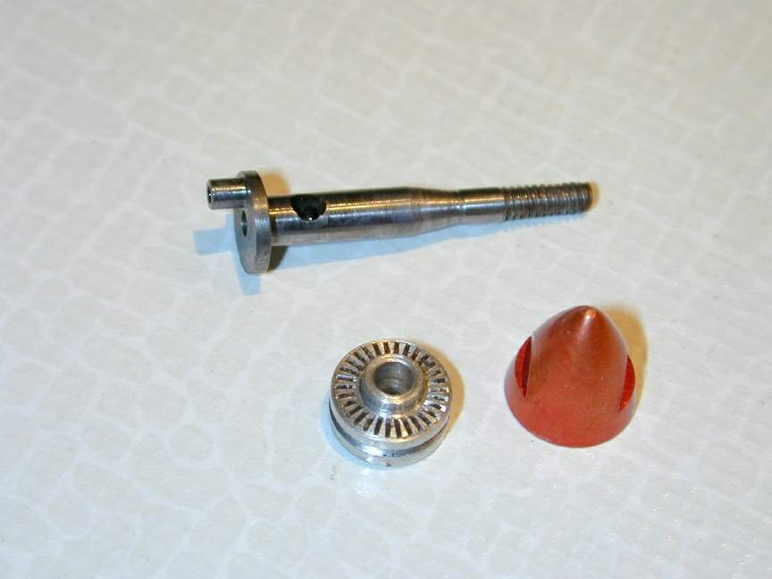
This photo shows the tools used to make a prop drive washer (in this case, for the ED Baby). The knurl holder is simply a piece of 1/2" square steel with a hardened and tempered piece of 1/4" drill rod poking out near one end. The peg length is set to the height of the knurls to be used. The steel shank goes in a tool post holder with the center of the peg set to lathe center height for "straight" knurls. The holder was designed this way because many prop drive washers have a boss in the center. This boss would probably prevent a "U" shaped knurl holder from getting close enough to the center of the driver to form the knurl. In practice, I've had no trouble with the unrestrained knurl trying to spin off the peg.
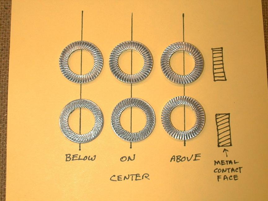
You can set the knurl tool above or below center height to produce a spiral knurl, or use a spiral knurl--but be aware that a spiral that bites into the prop for normal rotation is almost guaranteed to throw the prop in the case of a backfire.
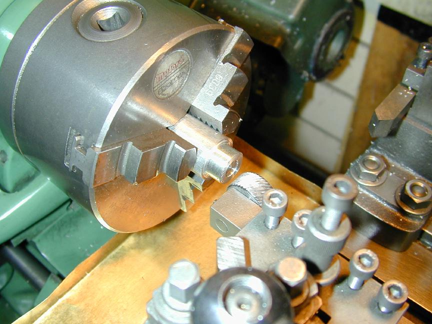
Begin by reducing the stock to the final diameter required for the driver, then counter-bore to a depth of about 0.016" to produce the "band" that will be knurled (as seen in the photo here). The knurl is formed by plunging the knurl into the face of the drive washer with the work running at about 500 rpm (the speed is not that critical, and there's no advantage in running slow). Running the cross slide in and out by 1/32" or so while the knurl is running may help clear the chips and form the V's, but is not strictly necessary either. If you do this before the driver is profiled and parted off, the stock can be gripped quite tightly with no danger of marring the finish.
The knurling operation is violent, and the chips tend to be trapped and mashed into the driver face, marring the pattern. Since most model engineers don't have a high volume flood "suds pump" on their lathe, brushing the chips out with a brush dipped in cutting lubricant (or kerosene for aluminium) would be a good substitute were it not for the fact that normal lathe spin will try (and generally succeed!) to snatch the brush bristles into the job like an old fashioned mangle. For this reason, I knurl with the lathe running in reverse. Even if your lathe does not have a cam-lock spindle, there's no danger of the chuck unscrewing with the knurl pushing against the job.
When the knurl looks well formed, take a light skimming cut over the outside diameter of the driver to remove the metal burr that will have flowed out at the edges of the work. Repeat on the inside of the band if it looks warranted. Many drivers actually undercut a small lip about 0.010" wide around the edge to just more than the depth of the knurl to protect the tips of the V's at the perimeter. I'm not sure this is at all effective, but it can look attractive!
This process will form very clean knurls, provided that the width of the knurl band is kept relatively narrow--say 1/4" at the maximum. The reason is simple. The knurl band is sort of like the data band on a CD, and like this data, the bits on the outside edge will be rotating faster than the those on inside edge.
The straight knurl on the other hand must run at a constant velocity from one edge to the other. So if the outer edge of the job, where the cut is deeper sets the velocity of the knurl, it will be travelling too fast at the inner edge. Something has to give, and the knurl will constantly skip from V to V.
To do this, it has to skip in and out of mesh. This will be evident as a "blurring" of the V pattern, generally towards the middle of the knurl band. The wider the band, the greater the speed differential and the worse the effect. On a narrow band the effect will be less noticeable, and really narrow bands may have no mutilation whatever.
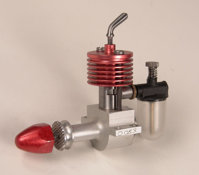
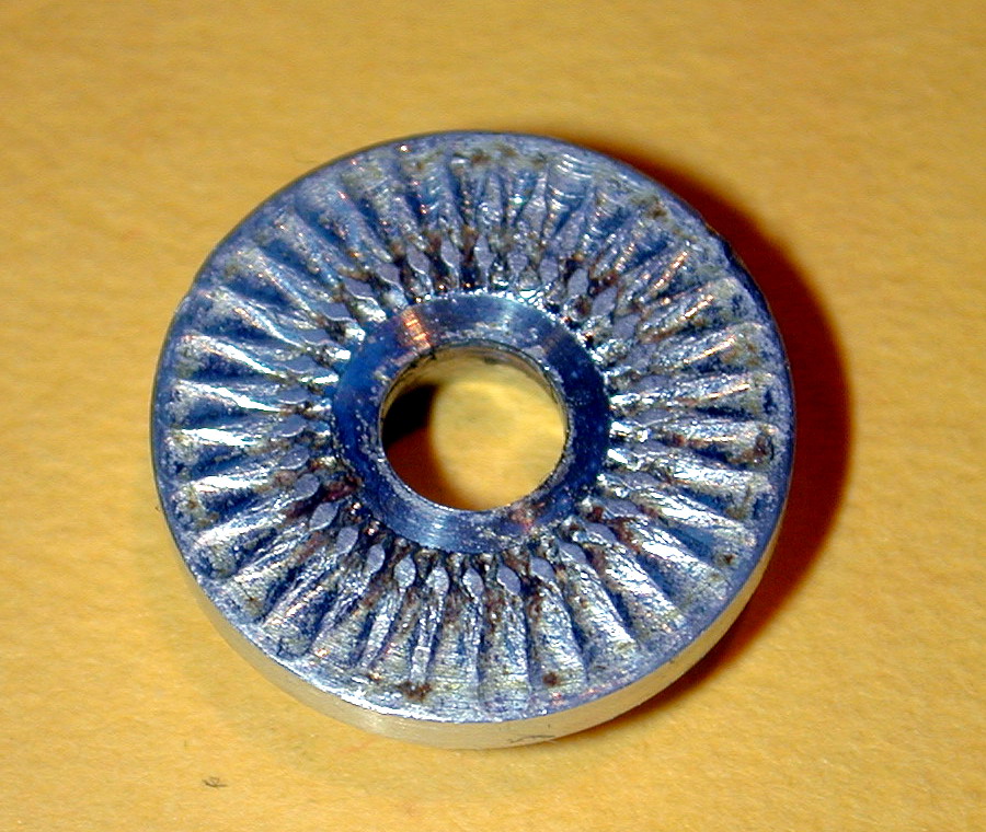
 Look closely at the knurl on the one-sixth scale Cirrus Mk I here. On first glance, it looks good, but look closer in the two o'clock position. The angle of the photo there shows the feint marks near the center of the knurl band where the knurl has been riding up and over in a doomed attempt to travel at two speeds at once. The effect is worsened as the angle between the knurl axis and work face approaches zero. I've seen drivers on commercial engines that are really bad--they obviously didn't know about the "angle the knurl" trick.
The full and complete answer is a special knurl shaped like a bevel gear. Now the knurl can achieve a degree of angular velocity variation across its face too. Such tools are rare. Dan Calkin used one, and the knurls on ELF engines are absolutely perfect (see Figure 15-69 on page 203 of John J Brown's book "Dan Calkin And His ELFs").
This page designed to look best when using anything but IE!
Copyright (c) Ronald A Chernich, 2004. All rights reserved worldwide.
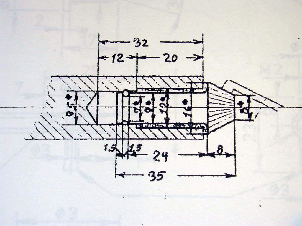 The Theoring diesel plans show such a tool as well--an item which has mystified many readers of the plans (the prop driver is the L shaped, partially sectioned thingie to the upper right of the diagram). The knurl teeth could be produced by shaping and indexing with the tool path such that the depth of cut lessens as it approaches the apex, or by using standard bevel gear milling practice as described in Ivan Law's book. I truly plan to make one of these someday (so much to do; so little time).
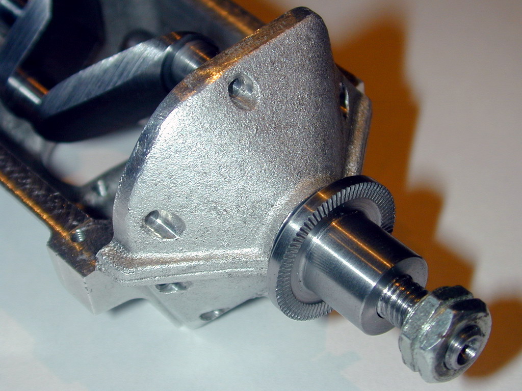
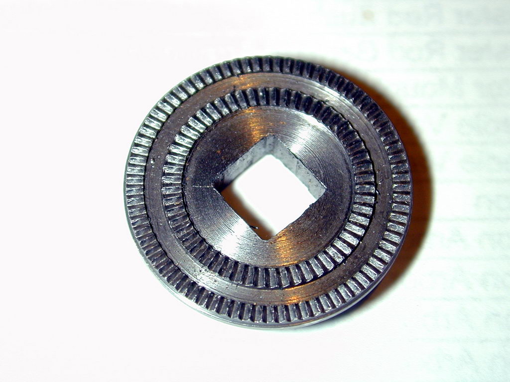 As noted above, if we try to plunge knurl a wide band with a straight knurl, the radial speed differential across the area being knurled will require the knurl to do ugly things to the peaks and valleys. There is a trick you can pull in this case. Instead of trying to knurl the whole area, divide it into two narrower bands, and knurl each separately. This technique was employed by the English manufacturer FROG (Flies Right Off Ground) on their Frog 500 5cc glow engine (and later, the Frog 500 ignition engine!). In this photo, the driver diameter is 7/8". The band to be knurled was 3/8" wide which I know from experience would be marginal to poor with a straight knurl. By dividing it into two 1/8" bands, two very neat and well defined knurls are produced. This is better, gripping-wise--than a single, poorly defined one like the "commercial" job below.
Conclusions
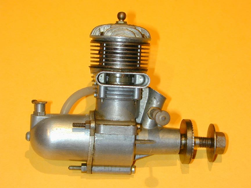
 The plunge knurl process gives quite acceptable results, once you understand the limitations and work within them. The trick is to angle the knurl to approximate a series of peaks and troughs that converge in the center. Ideally, a knurl with an angular face allows better "meshing" and will produce a better defined pattern. But a standard knurl will produce fine results if the width is kept to no more than 1/4" (about 6mm). Wider than that, consider using two thin knurl bands. They will be well defined (and look neatly different too). With a little practice, you'll be turning out better knurls than many "commercial" jobs like the DC Sabre pictured here. Now don't tell me you can't do a better job than that!
![]()
Please submit all questions and comments to
[email protected]
