How To Grind Needles for NVAs
Updated: December 29, 2006
Click on photographs to view in more detail
![]()
This page describes some ways of making the needle part of a needle-valve/spray-bar assembly--NVA for short. The rest is described on the NVA How-to page. As explained on that page, fuel regulation should take place between the tapered needle cone and the small diameter hole that forms the "needle seat". For an evenly regulated flow, it is important that no air should leak into the spray bar. This means that the parallel length of the needle should be a close sliding fit in the spray bar. As the smaller diameter fuel inlet hole will be drilled concentric with this hole, it should be obvious what the essential characteristics of the needle point must be:
- The tip of the needle should be on the axis of the needle wire
- the section should be circular everywhere along the taper
- The taper must be regular and finely finished
- The length of the taper should be such that the shoulder does not occlude the spray bar hole when the needle is "open".
Note the things that the needle does NOT have to be:
- Sharply pointed
- Neither cone shaped, nor some square law, rounded taper.
If you can get them, large darning needles make excellent needles for many types of application. In fact, a number of older commercial engines have used this as their needle valve. With practice, an acceptable needle can be ground free-hand. This was described in the February 2003 Issue of Model Engine News. The technique about to be described was developed out of frustration with the number of rejects I was experiencing grinding and finishing them off-hand. Like a lot of model engineering tasks, it will take a lot of hours to make the tooling. But once this is done, perfect needles can be made from inexpensive hobby-store music wire in minutes, first time, every time.
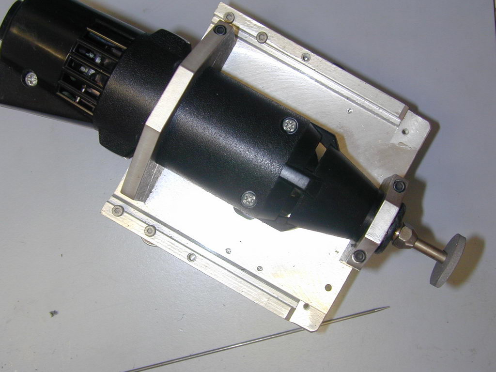 The tooling is based on the now inexpensive high-speed hand tools made by Drelmel (R) and others. A special holder is required to clamp the tool roughly on the lathe axis so it can be used as a tool-post grinder. The Dremel's bearings are not good enough to use it as a tool-post grinder capable of grinding crankshafts and cylinders, but with a little work, it will do a more than adequate job on needles. In this photo, two clamps made from 1/4" thick aluminium plate are bolted to an old dead disk drive plate to hold the tool. A bar on the underside of the plate allows it to be quickly mounted in my lathe's quick-change tool post. With the bar removed, this jig is also used in conjunction with a guide and table assembly to slice up carbon fibre sheet for free-flight wing spars.
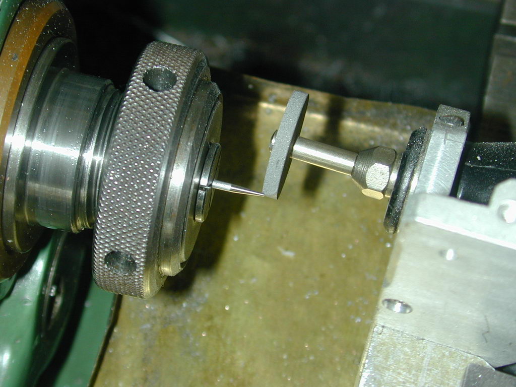
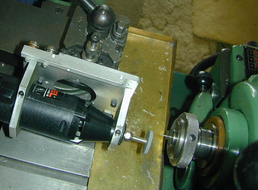 The needle is ground into the tip of a piece of suitable music wire (1/16" is the must universal choice) by setting over the compound slide by 4 to 5 degrees. This shot, taken from the back of the lathe looking towards the operator shows the tool ready for use. The stock is held in a collet to provide optimum concentricity. If the wire is not spinning on the axis of the lathe, the point will not be concentric with the wire and the needle will either leak at the closed position, and/or cause adverse wear in the seat.
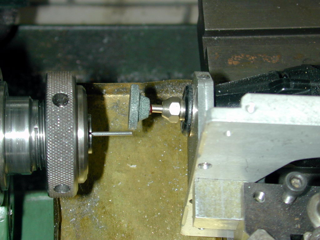 The Wire is gripped with minimum overhang and the lathe set to run at maximum speed. Normal rotations would be such that the relative surface speeds subtract, so the lathe will have to be run backwards. If you can't do this, run at the slowest possible forward speed. In this shot, a Dremel #85422 Silicon Carbide disk 25/32" in diameter (19.8mm) is being used. These stones give a better surface finish than the aluminium oxide equivalent (part# 8215), but neither are good enough for the finish required, merely for roughing down. Note that the wheel is set to cut at the rear of the work. This minimises the degree to which the job is obscured by the wheel. Take light cuts, running the wheel over the work several times at the same cross-slide setting until the job no longer sparks. Then advance by 0.001" and repeat until the end is approacking a point. Points are not bad, just unnecessary--you're not going to sew with it--it just needs to be smaller than the needle seat hole.
 When the roughing out is done, change to a #425 7/8" Emery Impregnated disk mounted on a #402 mandrel. Repeat as before. You should only need to reduce the needle by another 0.002" or so to achieve a highly polished finish. Naturally, with the wheel at the rear, the sparks and dust will be being thrown towards to you, so take whatever precautions you deem appropriate. Some extra lathe bed protection is not a bad idea either as the particles thrown of are highly abrasive.
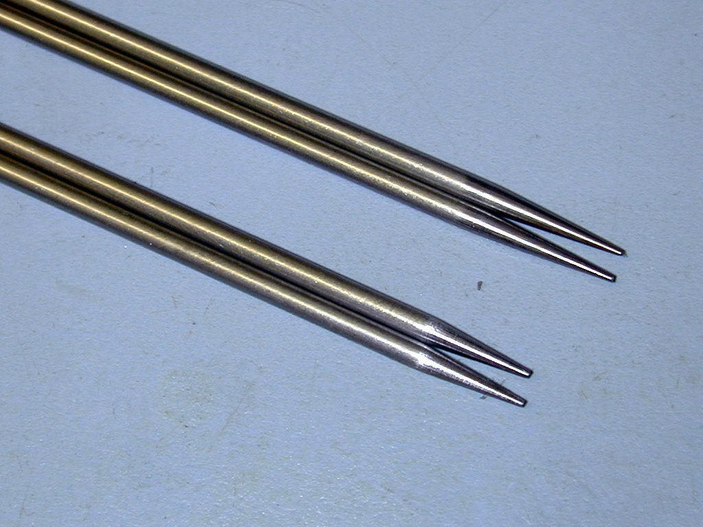
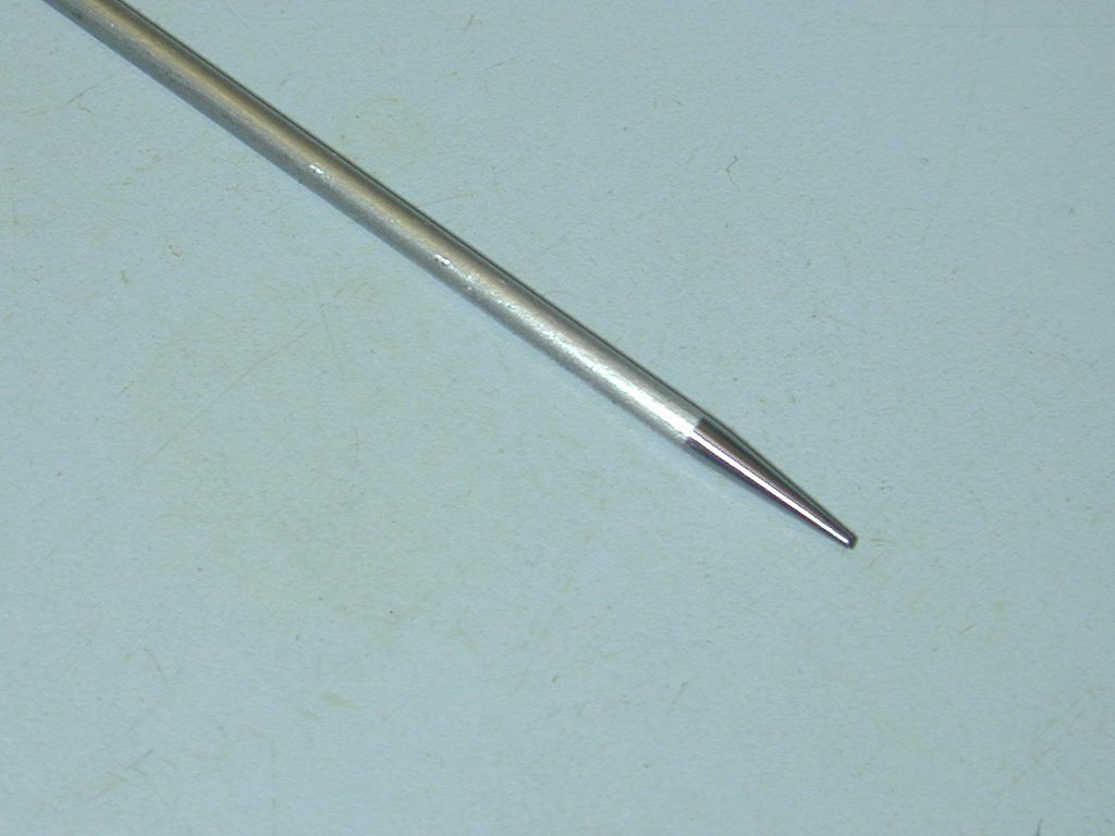 Here, as they say, is the proof of the pudding. If the cone we've ground onto the end of the wire is concentric with the wire, the shoulder will be at right angles to the wire axis. If it is not, the shoulder will wobble along the axis as the needle is rolled about. This is as about perfect as anyone could hope for. Next step is to clean the wire to a bright finish with a piece of folded over 800 grit glass paper and a touch of oil. It's easier to do this before the finished needle is cut off the stock--another job for the Dremel using a #409 Emery wheel--much neater that side cutters!
If all this seems a bit of bother, read the Gee Bee 50 review for how Gordon Burford made needle valves in the early days of model engine making in Australia.
![]()

This page designed to look best when using anything but IE!
Please submit all questions and comments to
[email protected]