GHT UPT
Construction Log:
Ball Handles
Created: November 2006
Ahhh, ball handles; I LIKE making ball handles! Yes, the tommy-bar design used by Mason, or the little commercial ratchet handles endorsed by the Australian UPT casting supplier, Hobby Mechanics, are totally practical, functional, and even superior in that you don't have to fiddle around getting the washer thickness correct to position the handle angle, and will never have them interfere with the table, or anything else. But a perfectly made ball handle says something about the maker. So shoot me...
 Sadly, I could not make these guys in one piece as described on my Quorn Construction page. They are just too short to provide the overhang needed to get the Hemingway/Radford "up 'n over" ball turning tool in and still have something to grip on. So these handles have to be made precisely the same way that GHT describes in his book, The Model Engineers Workshop Manual; namely with a separate small end ball that is drilled and pressed or glued on later.
The "up 'n over" (my name) ball turning tool used was designed by Kiwi, Jack Radford. It appeared, naturally, in the Model Engineer, and in the book of Radford's collected tools [1]. A kit of parts with plans and instructions for a slightly modified version can be bought from Hemingway in the UK, which is where mine came from. The tool is basically a pivoted, tangential cutter. It does a beautiful job, especially in leaded steel like 12L14. But for the little balls which are 7/16" in diameter, all I had was some very ugly mild steel stock that almost defies a good finish. The tangential cutter does a remarkable job on the hideous stuff making me think I should change over to tangential cutters for everything!
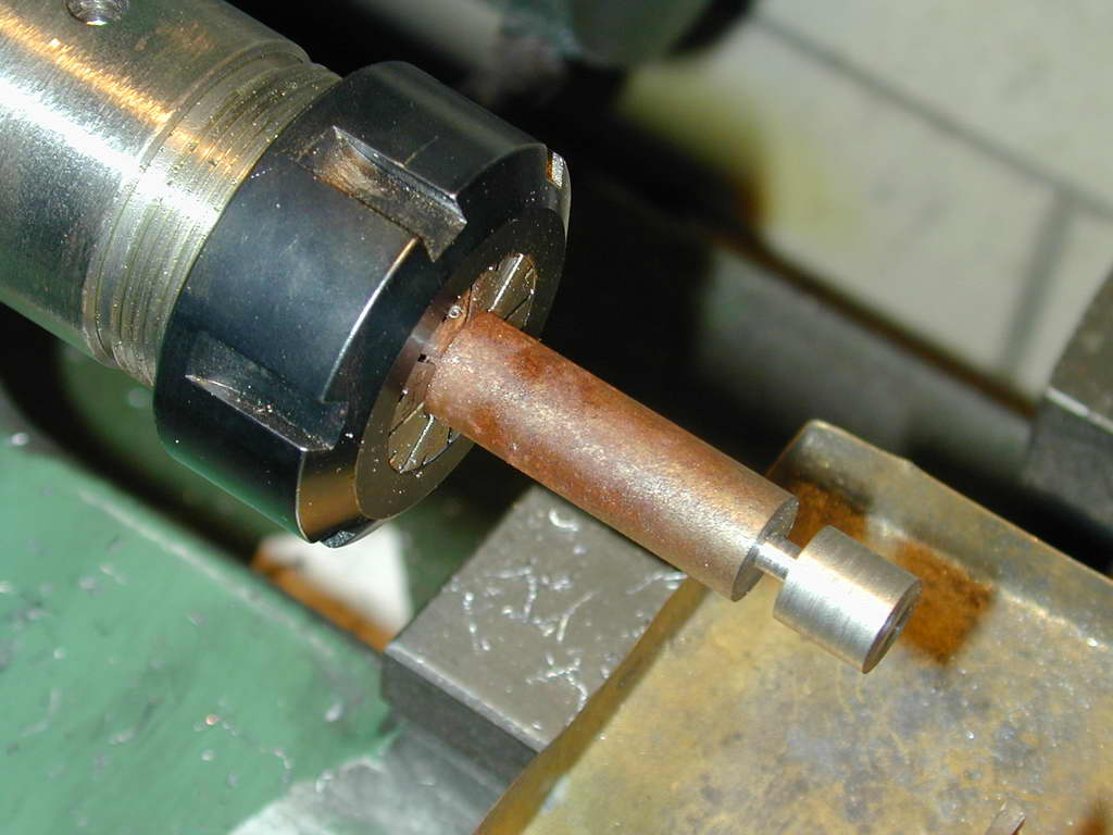 Photo 28 |
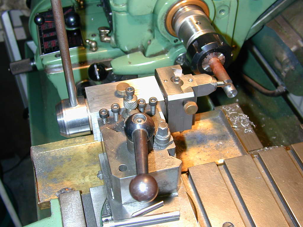 Photo 29 |
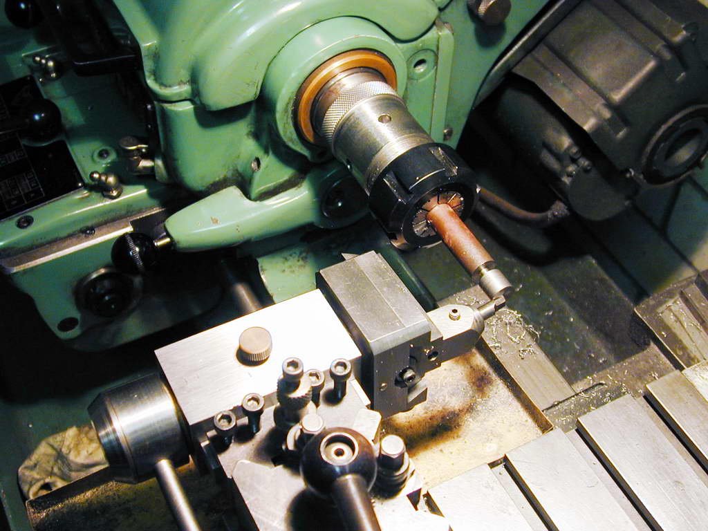 Photo 30 |
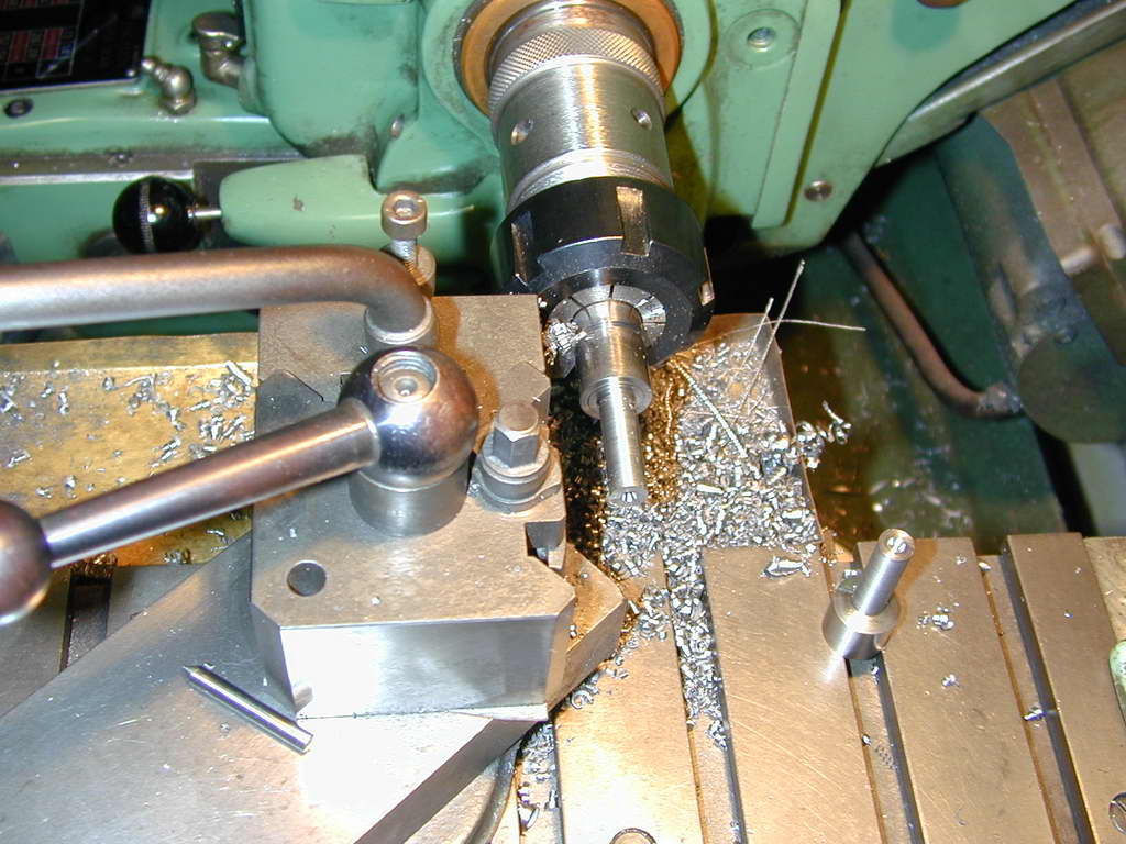
Photos 28 to 30 show the setup. First (28) the blank is prepared by turning down to the required ball diameter and cutting a groove for the cutter tip to rotate into. As can be seen, an amount of overhang is needed to accommodate the body of the tool when it is rotated to face the chuck. The "stem" is just a little less that the small handle shank diameter as we will be parting the ball off when it is done.
With the axis of the tool pivot set precisely on the lathe center height, the cross slide is adjusted until tip is on the vertical plane of the lathe centerline. The cross slide is then locked. The tool tip is positioned anywhere over the blank and adjusted until it just touches the surface (Photo 29). If rotated, the tip will now describe a circle of the ball diameter. Finally, we move the saddle towards the tailstock, rotate 90° and lock the saddle with the tip touching the face of the blank (Photo 30). This centers the tool on the ball-to-be.
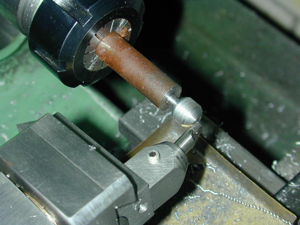 Photo 31 |
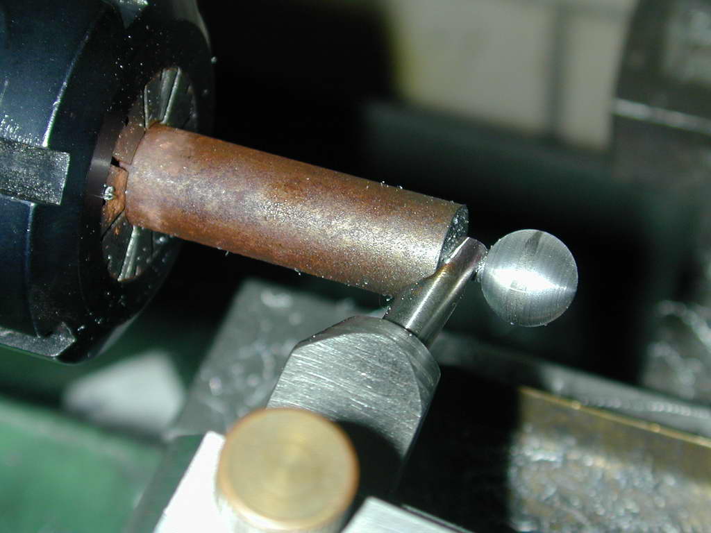 Photo 32 |
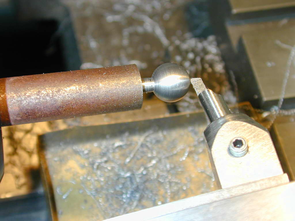 Photo 33 |
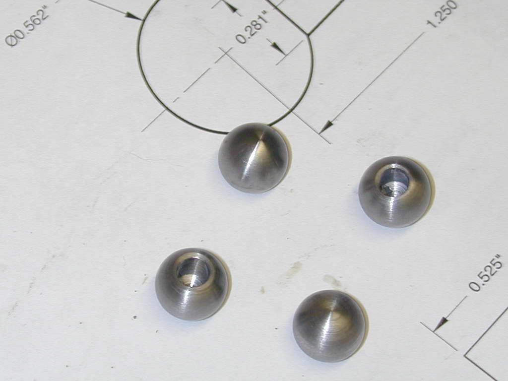
The adjustable slide must now be extended so the tool can make a starting cut on the corners of the blank. After the "up 'n over" cut is complete, the slide is screwed in a bit and another cut taken. Photo 31 shows progress about half way towards done. The two spherical ends will gradually come together. In Photo 32, you can see the feint witness mark in the center just before the two merge. In Photo 33 the ball is complete and the tool is back to the ball diameter setting. A new blank can now be chucked touching the tool tip to the faced end as in Photo 29, making "production line" turning a snap.
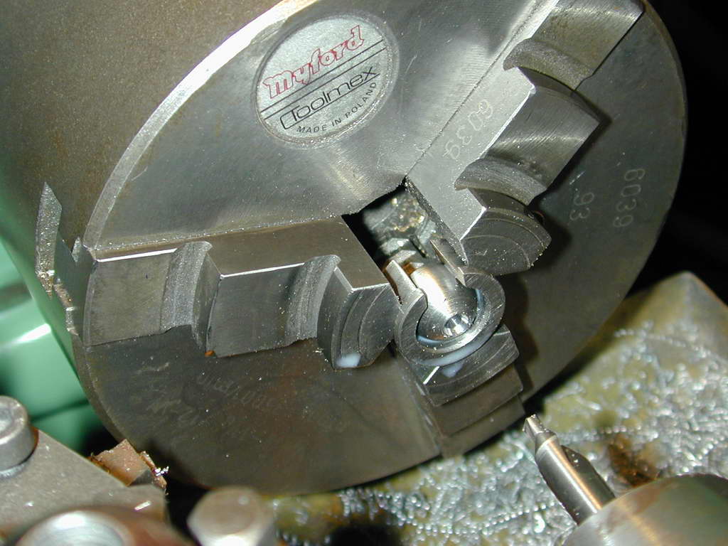 GHT describes how to make little pot-chucks to hold the balls and embryonic ball handles for second ops. Curiously, he never twigged to their use for making the ball handle washer thinning process easy. More on that later. In this photo, a ball has been gripped, faced, and drilled to accept the other part of the handle.
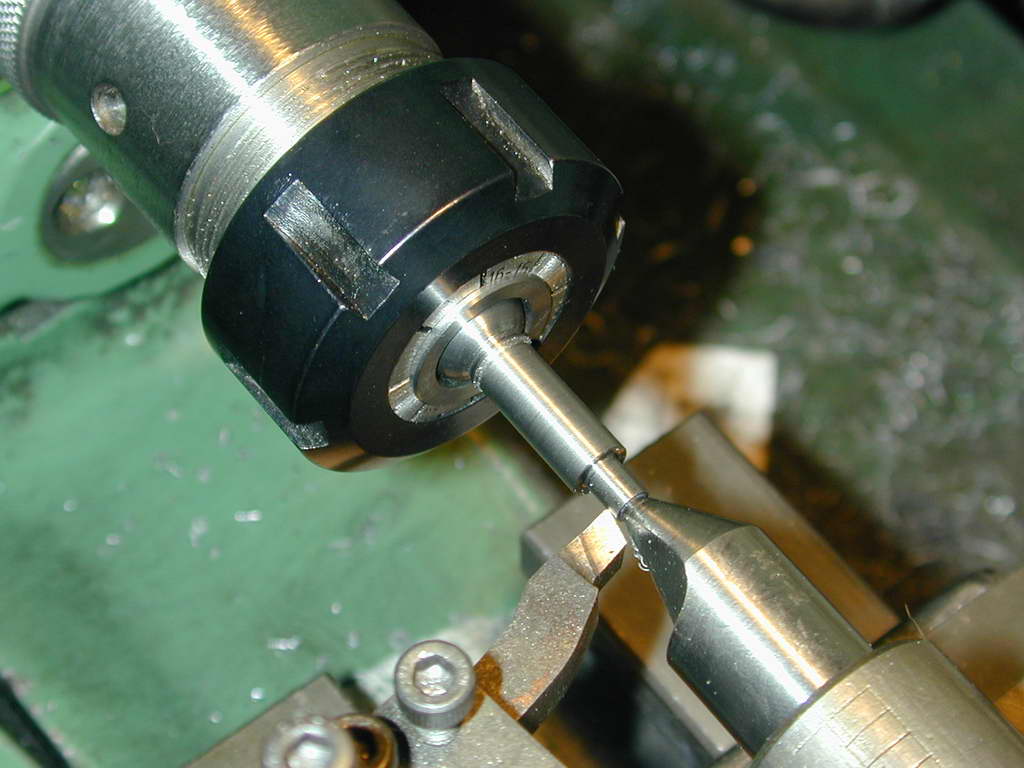
 The "big end" balls are production-lined in a similar way to the little ones, except this time, the blanks have the shank turned down to a couple of thou larger than the major diameter of the tapered shank. In this shot, a blank is being parted off. You can see a finished one on the saddle. Note the center that has been drilled in the end of the blank. This is vital. If you forget it and turn the ball, you've just made attractive scrap!
 Photo 37 |
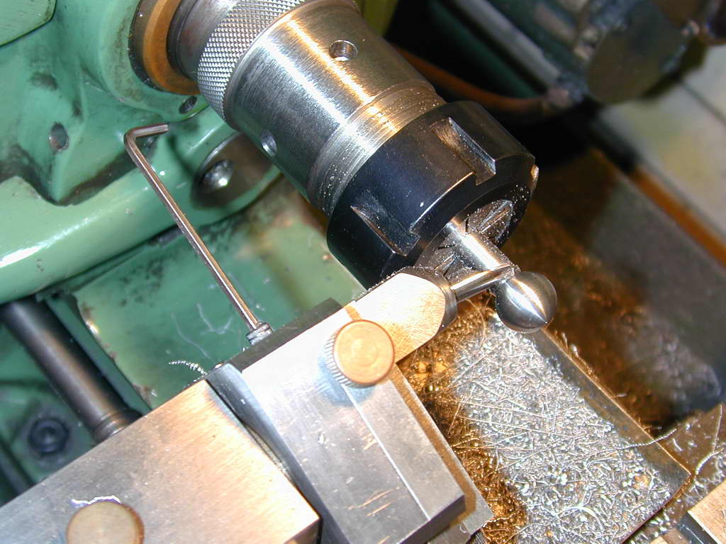 Photo 38 |
Photo 37 gives the operator view of the tool with the long arm providing a good degree of feel. The Allen key in Photo 38 is the way the slide of the tool is adjusted. The knurled brass knob next to the cutter holder is a gib-lock that I soldom use. The other knurled brass knob can be used to lock the tool rotation, or adjust the operating friction, and hence, "feel".
 The blanks are now gripped by another pot-chuck (9/16" diameter this time). Obviously, this will grip only on a point-contact around the diameter, but with support in the center drilled end from a tail-stock dead center, and the ball pushed back against the "floor" of the pot-chuck, the setup is completely rigid. In this shot, the shank that will be Locktited into the small ball is being turned.
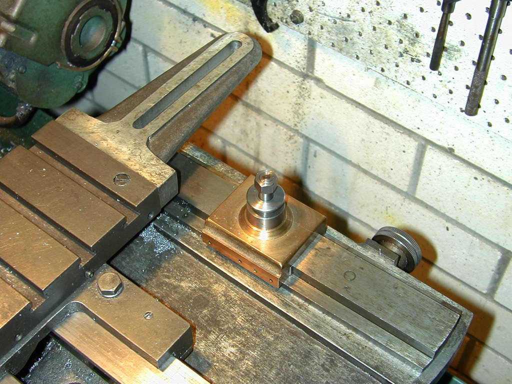 Photo 40 |
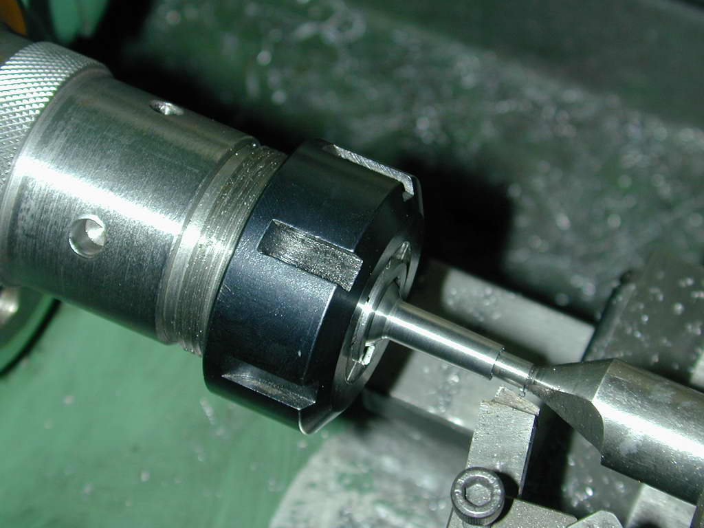 Photo 41 |
The shank is taper turned 2°. While this could be done by setting over the top-slide, an excessive tool overhang is required to get the compound slide clear of the tailstock support. Turn it around the other way and it, or your precious fingers may be hit by the chuck! Luckily, I have a taper turning gizmo (another kit from Hemingway) that requires the top-slide to be rotated 90° to act as a cross slide. The actual cross-slide is detached from its lead screw by loosening the screws that hold the cross-slide nut, dial, and handle assembly. This allows the cross-slide to move under control of the slider on the adjustable bar at the rear of the lathe (Photo 40). Photo 41 shows the shank being taper turned and faired into the larger ball with a large-ish radius on the tip of the tool.
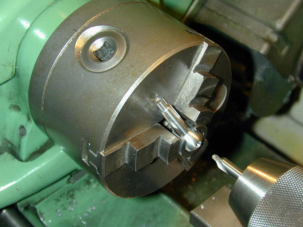 Photo 42 |
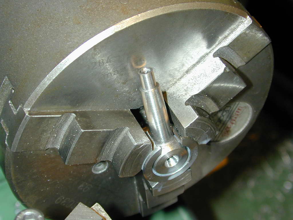 Photo 43 |
Almost done. Here we see the absolute beauty of GHT's pot-chuck design. The large cut-out in the side not only allows the pot-chuck to close and grip the ball, it also provides clearance for the handle such that when the tip touches the chuck face, the handle axis is 20° off the lathe axis which is just where it needs to be for these handles. The large ball is now drilled and tapped for the cotter studs. The final stroke-a-genius in this design is the width of the pot-chuck flange and depth to the inner "floor". This has not only given us the correct handle angle, it is also the reference for facing the handle to the correct flat diameter. No measuring needed.
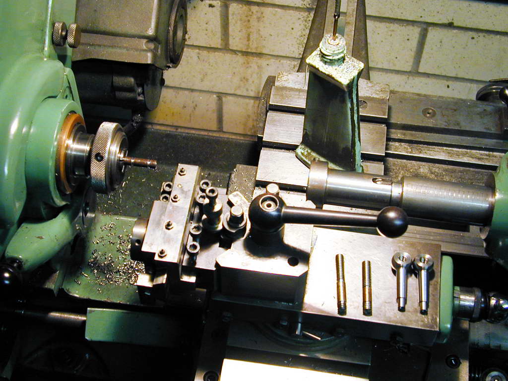 Photo 44 |
 Photo 45 |
The last parts to make are the studs for the cotters and the washers. The plans call out the thread as 1/4" BSF (British Standard Fine: 24 TPI). Since I have a good stock of UNC 1/4-20 cap head screws, that's what I used as temporary clamps for the cotters when boring the arms. A 60° 20TPI thread is 1/32" deep. I would not try to run a 1/4" die down a piece of rod and expect the thread to be of acceptable quality. In photo 44, the thread is being roughed down to provide a start for the tail-stock mounted, adjustable die. Photo 45 shows the manual mandrel handle used to finish the thread with the die.
 Photo 47 |
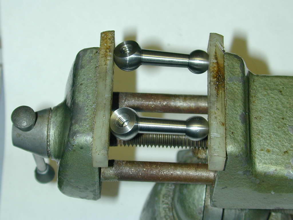 Photo 48 |
Here are the bits ready for assembly. The Locktite will act as a rather good hydraulic fluid and prevent the little ball from remaining pushed against the seat on the handle shank. So Photo 47 shows them clamped while the adhesive dries overnight.
Notice the washers in Photo 48? Like those used on the Quorn handles, the thickness of these washers sets the angular position of the handles when cinched up, so it is rather critical. GHT says this is difficult and talks about magnetic chucks and surface grinders, or lathe backstops and complicated setups. But nothing could be simpler, and he already has the solution: yet another pot-chuck! Tighten up a handle and decide how many more degrees it has to move in a clockwise direction to be where you want it. The screw thread in my case is 20TPI, so one turn will advance 0.050". Say the handle needs to be rotated another 90° to be where we want it. That's 1/4 of a turn, or about 0.012" of washer thickness. Pop the washer in a pot-chuck, touch the tool tip to it and face it back 0.010" (to be safe). Try the test again and adjust more if needed. Those washers are called out at 1/8" thick, so you've got plenty of room for adjustment—even more if you've actually used the BSF thread.
So there we are, ball handles done. Time to feel proud, smug, and superior (commercial ratchet handles indeed! Phahh.).
References:
| [1] | Radford, JA: Improvements & Accessories For Your Lathe, TEE Publishing, Warwickshire, England, 1998. |

| Back: Arms | UPT Index | Next: Table |
 Model Engine News Home
This page designed to look best when using anything but IE!
Please submit all questions and comments to
[email protected]
Copyright (c) Ronald A Chernich, 2006. All rights reserved worldwide.