A RANK BEGINNER BUILDS
THE QUORN
UNIVERSAL CUTTER AND TOOLGRINDER
Ron Chernich, 1996.(Revised 1998, 2003, 2005)
In George Thomas' (GT) great and posthumous book, The Model Engineer's Workshop Manual, GT's editor, William A Bennet observes, "The Quorn must be mentioned, if you have made this T & C grinder and can use it then you have established your pedigree as a model engineer!" (p76). Well, I've done it and the only thing I feel so far is older and wiser, which is not to say the heavens will not open up Real Soon Now (after the backlog has cleared) and my scrap box shall be anointed by a beam of light and thus remain forever innocent and empty. T'aint happend so far, though... In this short article, I'll share some tribulations and valuable lessons the exercise taught me and tell you a few things which are not in Professor Chaddock's book. Hopefully these will be informative and of interest, especially if you ever embark on building a Quorn.
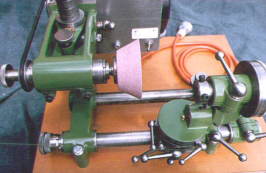
First some background. I took delivery of my lathe, a Myford Super 7, in February 1995. Prior to this, I had some very limited machining experience way back in the 60's as part of an electronics apprenticeship (we were expected to be able to make chassis for prototype devices back then). My normal work for the past 20 odd years has been with computers which fit well with my love of precision and complexity. All this made me a natural victim for the "Quorn", with its myriad of ball handles, graduated scales and spring loaded bits and pieces.
So as a rank beginner machinist, intent on building model internal combustion engines, I ordered a Quorn casting kit, motor and grinding wheels and decided what other tools I would need to make in order to build the thing itself. In retrospect, the problem was recursive: the tools I needed to make in order to build the Quorn would have been easier to make if I'd had the Quorn in the first instance! Looking back, the work involved in building the Quorn is largely straight forward and easily accomplished with standard home shop equipment. There are however, a few operations which are not as straight forward as they seem. In no particular order, these are:
- Spherical turning
- Dividing and graduating
- Precision boring
- Turning a "quickstart" thread
- Trepanning grooves
- Bringing out the finish on cast iron
- Base
- Micrometer
- Rotating Base
- High Speed Spindle
- Work Head and Division Plate
- Tool Holding Spindles and Arbors
- Errors and omissions in the instruction book
Spherical Turning
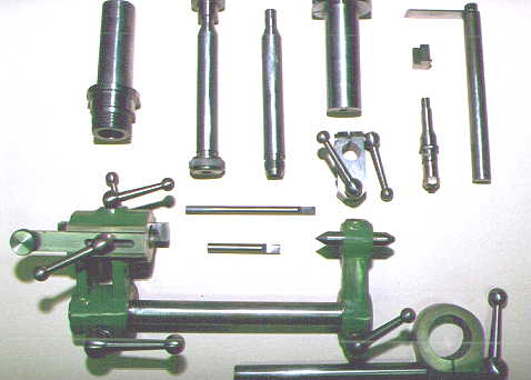
The Book states there are eight small and nine large ball handles to make. For convenience, these are shown in Figure 1. To pre-empt the last section to this article, there are actually ten large handles needed, but more on that later. With this quantity, I wanted a method that produced good looking handles with minimum fuss and no waste. This topic has supposedly been done to death in the literature. GT devotes a chapter to it in his Workshop Manual (which itself, reprints material that appeared in Model Engineer); Mr WJ Foulkes covered it in a two part article appearing in Engineering in Miniature, (Vol 15, p108 and 138). Professor Chaddock himself devotes space to it in The "Quorn" Universal Tool & Cutter Grinder, which I shall call "The Book" and assume that all aspiring, or even just plain curious Quorn devotees will already posses a copy.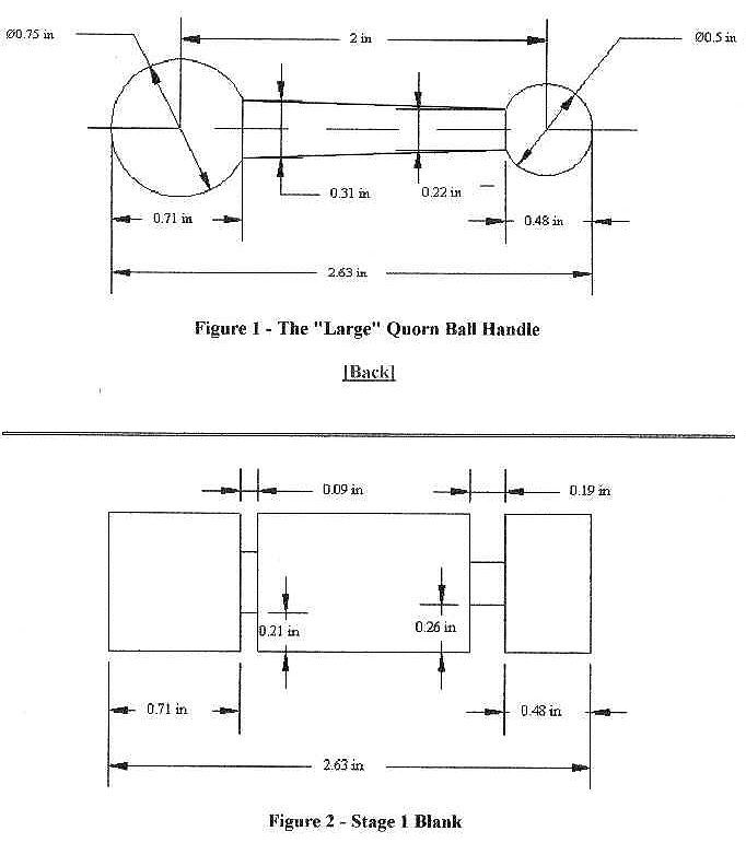
All three propose different ways of tackling the task. The good Professor uses a form tool made out of an old file which he has annealed and re-hardened. Perhaps files were more plentiful in those days but even my oldest ones are still useable and I was doubtful of the amount of horse power required to push a 3/4" diameter cutting edge into a lump of mild steel. The method has no waste, but looked impractical, so on to method two.
The redoubtable GT used an "up and over" spherical turning tool to produce his handles. To simplify work-holding, he made special collets and made the handles in two pieces, parting off and drilling the smaller ball, which is then loctited to a stub on the tapered shaft integral with the larger ball. The "up and over" tool is nice and Messrs Hemingway provide a kit of parts and plans for it at a reasonable price. GT's ball holding collets are dual purpose and simple to make, so they are a logical choice. But the two part bit just did not appeal to me at all.
Apart from the extra work involved, it's wasteful and not elegant. The Foulkes method makes a one piece handle, also using the Thomas/Radford "up and over" tool, but with little stubs at each end to hold the work during production. These are finally removed with a GT hand graver and rest. While Hemingway also provide a kit for the GT graver rest, I thought this was even less elegant that the two part idea. It also wastes even more metal. My solution combines these all three so that I have a one piece handle with fully formed balls (turned with the "up and over" tool) that waste no metal. First, I bought and built the Thomas/Radford tool from the Hemingway kit. The finish on this was produced using a belt/disk sander attachment that replaces one end of my shop grinder, forming a linishing machine. This gadget is totally invaluable for smoothing and putting a lovely "brushed" finish on steel. I could not live without it, or something like it.
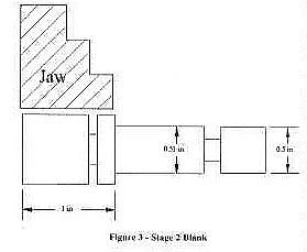
The Ron Chernich (or arr-cee, if you prefer) method requires you start by parting off lengths of stock equal to the desired handle length as shown in Figure 2.. These are next grooved at each end using a parting tool as shown in Figure 3.. You will notice that the axial length of the material from which the ball will be produced is less than its finished diameter. This is because the tapered shaft truncates the perfect sphere by an amount that can be calculated with elementary (and largely forgotten) trigonometry. The depth of the cut is set to be just short of the tapered shank at each end. Two cuts of a 3/32" blade are needed at the small ball end to provide adequate clearance for the turning tool. A little fore thought will produce a production line setup to do all like-sized handles as a batch.
Next we reduce the blank for the small ball to the required diameter and part of the shank to a few thou larger than this size. Later we will grip on this in the 3 jaw SC chuck and by leaving it say 10 thou larger than the ball, we can avoid marking the small ball. This step, also done in batch is shown in Figure 4.. We can now turn all the small diameter balls using the set-up and method described in the excellent instructions that accompany the Hemingway kit. If you do not alter the tool setting after taking the final cut, the cutter itself can be rotated to the tail-stock end of its arc and used as a stop to correctly position the next blank. This means that the initial set-up process need only be done once.
During this process, the blank has been gripped in the SC chuck on the large ball area, plus the part of the blank that remains at this diameter. The partially finished blanks now get the "thick" end of the tapered shaft reduced to its finished maximum diameter, again in batch, resulting in the shape shown in Figure 1. The spherical turning tool is now set to make the large balls, with the blanks gripped in the 3 jaw SC chuck by the handle shank, which has as already mentioned, been left large enough diametrically to protect the small ball. Again the finishing cut permits the next job to be positioned accurately for forming. We are now ready to do the taper turning.
While it worked for me, my setup for this is a bit delicate and could be improved. Basically, we use a GT-style collet to hold the blank by the large ball in the 3 jaw SC chuck. The other end is supported by a concave live centre in the tailstock. If you have one of these, great. I didn't and simply turned up a short length of mild steel to have a 60 degree (included) internal taper that fitted over my normal live centre for about half the tapered point length. The other side of this bush has a 90 degree included taper recess that centres over the small ball. This little bobbin gets clamped between the little ball and the tailstock live centre with moderate pressure. With a little nudging of the setup, you can get the part of the shank that we have just used as grip length while turning the large ball to run true.
The process described so far has been aimed at arriving at this point with as little metal remaining to be removed from the shank as possible (a good idea, given the delicacy of the final setup). We also want a minimum effort solution, so the self-act can first be used to further reduce the blank before taper turning. Some more simple trig gives the angle the compound slide needs to be set over to produce the tapered handle shank (assuming you don't have a taper turning attachment). Provided you take light cuts (I never took more than 15 thou per pass), the setup is rigid enough for the job. The tool used should have a radius on either side that approximated the radius used on the bit in the spherical turning tool, allowing the tapered shank to neatly blend into the two balls.
The taper angle is adjusted for the desired result on the first job and all the remainder run the all through like sausages. All that remains now is to face off the large ball for drilling and tapping. This is done in the same GT collet that held the handle for final turning. WARNING! GT's collets will produce a handle that is angled to its bolt by about 15 degrees. The Quorn drawings call for 25 degrees. Even if I'd thought about it, I probably would have decided that it didn't matter a damn and gone with the shallower angle. This is fine, except for the octopus cluster of handles under the rotating base that depend on 25 degrees for assembly clearance.
When I found this out (and calmed down), I was faced with either making some 25 degree handles, or finding another solution. Wisely, I chose the latter and ended up with a machine that is mush easier to assemble and operate than the standard model would have been. There are three handles involved. Moving front to back these are the tilting arm, the rotating base and the sliding base clamps. The 15 degree problem prevents the rotating base lever from being fully fitted, but by extending its clamp bolt and fitting a spacer to this bolt to bring the rotating base handle out in front of the tilting arm, assembly is no longer the Chinese puzzle described by Prof Chaddock and accessibility to all three is improved.
I used the compound slide tool holder (a Myford-Dixon type) as a guide to keep the tool square. The view is somewhat obscured by the tool holder, but you can "even up" the stamping depth after by manually jiggling the punch into the formed impression and applying a few more taps, subtly angling the punch to increase the depth in the desired direction. The only mistake I made here was to forget to lock the saddle while punching the division plate. Eventually, I noticed that the band being punched was wandering. I guess I could have turned it all off and started again, but after getting 360 divisions right in three heights, I didn't want to tempt fate.
The Radford tool has a rotary depth stop that sets the length for units, fives and tens marks. These are cunningly arranged in sequence 5-1-10, so from the most commonly used position (units), only one detent click is needed, either clockwise or counter-clockwise, to reach fives or tens stop. The intent is to reduce the chance for error. I found the most practical way to keep your place is to count out loud. The human short-term memory can generally hold only seven pieces of data (Aside: There is a neat proof for this. See if you can sort the days of the week alphabetically, in your head. Most people can, even if the facial expressions get a bit odd during the process. Now try it on the months of the year. Very few people can. This shows that the capacity of the short term memory capacity is exceeded somewhere after seven and before twelve. End of Aside).
If you count out loud, one through ten, then even if your mind slips into automatic and you suddenly wonder where you are and what you're doing, short term memory will recall the last number you physically heard, saving the day. On the micrometer thimble, it's best to perform this full procedure before boring it out. I think it's common sense, but going the other way around would probably distort the part.
Somehow, I went 18 thou oversize on the front bar hole (sigh, failed on the very first operation). Fortunately, I was able to recover from this disaster by making sleeves to fit the oversize holes. Still not thinking clearly, I made these press fits, so when I subsequently slit the RH front bore, its sleeve curled up and dropped out (The Book points out that slit things always close up. A third sleeve was made, oversize by the amount that the first one had gone undersized and to my surprise, it was an easy press fit into the casting.
I bought a cheep three stone, expanding break cylinder hone from any auto parts shop and used this to hone out the sleeves to achieve a good sliding fit on the front bar. In fact, this hone worked so well that it ended up being used on all the precision bored holes to take off the last half thou and improve the finish. One side benefit of this debacle is that by placing the split of my sleeve on the bottom of the RH casting (which is split at the top), I have quite an effective dust seal on these critical moving parts.
My front bar is still a bit tight and the pressure exerted by its spring is not always enough to keep it hard against the micrometer screw. But I've found that in use, the general vibration from the spinning parts overcome the excess friction and the assembly behaves perfectly. Better tight than loose, I say. While on the subject of the micrometer, The Book says to case harden the end of the screw where it bears against the front bar. I decided to simply drop a hardened ball bearing into the centre drilled dimple of the screw, holding it in place with some grease. I think this gives a more precise contact, with less friction, without the need to case harden a screw thread.
The only other "gotcha" that needs mention on this topic is probably only of note to beginners like me. That's setting up to bore holes which have already been cored in such a way that the hole is centred in the boss. This is quite difficult on the base castings, especially true when you've bolted two of the faces together, like I did. I hardly even thought about the problem at all and as a result, missed the boss centre for the front bar micrometer mount rather badly. Later, I became so obsessed with hitting the boss centre that I forgot about the need to sometimes position the hole relative to other things! The simple lesson, as in all things, is to think twice and cut once.
Trial assembly had ironed out some bugs and I was ready for final assembly and calibration. This led me to a dilemma, just slap on some paint, or go for a show quality finish? As you can guess from the heading for this section, I decided to go for broke. Not having done this before and not getting any help from the net, I had to re-invent the wheel here. The Book goes into great detail on this subject which Prof Chaddock refers to as "bringing out the finish". By this, he means raising the surface to the point where everything is smooth. GT's only words on the subject are to follow Professor Dennis' words on the subject, so off I went. I bought some polyester auto body filler and applied it to the RH base casting. Fortunately I decided to see how well it had adhered to the metal before doing the rest. The answer was: not at all.
The solution was eventually found in Strictly Internal Combustion, Vol 9, No 50. In an article titled "Finishing Your Engine", Randy Higgins recommended a Devcon product called Plastic Steel. To my surprise, the local stockist not only knew about it, but actually had it in stock, although "Plastic Gold" may have been a better name. This is an epoxy substance which seems to have iron fillings mixed with the resin. I found that it sticks to the castings, well, like glue, I guess. While still soft, it can be smoothed and worked by wetting you finger and sculpting at various pressures. This process tends to leave a thin area on top that is just epoxy and no iron filler, but that doesn't really matter.
I used a coarse, single cut file (similar to a "dreadnaught" file) to clean up the expoy filler as it soon clogged my old bastard files. Additional work was done with 150 grit wet and dry, used wet. There will be machined areas that you don't want to bring out. I saw a recommendation (in Model Engineer's Workshop, I think) that applying a crayon of the "greasy" type to finished surfaces would making removing paint from them a snap, so I decided to give this a go for the epoxy as well. The trick worked perfectly in both cases. Any excess epoxy was trimmed away with an Exacto knife and a blade I didn't care much about anymore.
After I was happy that the surfaces were close to flat, I sprayed on an etch primer coat, followed by cellulose auto body putty. This is available both as an actual putty and in a spray can. My aeromodeling experience says to use this stuff sparingly, as it will contract over time, so I used the spray variety and lots of wet and dry to only bring out the last few gullies. Finally, on went sprayed coats of undercoat and the traditional green enamel paint. Even though this process took a couple of weeks of spare time work, I am really glad I went to the trouble. The finished machine looks first class. My castings, while sound, had some cope and drag registration problems in places, plus some blow holes on one piece. I had added to these woes with a badly missed boss centre in one rather obvious location (the micrometer mounting on the LH base). The Plastic Steel allowed me to fix, rather than merely hide these problems.
Another sleeve would go on top of this to form the labyrinth seal. With the work turning between centres, off I went, getting a finish that looked like it had been turned with a rusty nail held in a pair of pliers. Taking fine cuts (about 5 thou), I tried everything I could think off in the way of tool shape, speeds and feeds. With a bare 10 thou to go before it went in the bin, I found the answer - just back the work up with a traveling steady! Now one of my standard general purpose knife tools would put a smooth finish on this uncooperative material. I finshed the last thou with 300 wet and dry paper, backed up by an old mill cut file, until the shaft was a press fit in the bearings.
Another point worthy of note is trepanning the end caps and the small pulley. I started out to make a hole saw, like The Book says, but decided that was not going to work. The instructor at a local trade school suggested I could probably do it with a plunging cut and well ground tool. To hold the caps, I made a sleeve with an internal thread to match the caps. Then, to my surprise (with considerable apprehension) the plunging cut (trepanning, I think it's called) worked! Overconfidence hit me on the second cap and the tool broke, leaving a fragment in the almost finished groove. I couldn't get it out, but remembered hearing that HSS can be machined, so with great trepidation and a re-ground tool, I went at it. Taking a very gentle feed, the "clack -clack - clack" finally disappeared. My HSS tool had machined away the broken HSS tool. Simply amazing.
Buoyed with this success, I attacked the small pulley labyrinth. This soon led to Yet Another Disaster (YAD) as the tool bit in and broke, destroying the finished boss along the finished keyway. Bother and fiddlesticks. My supplier said he could probably get a replacement, but it would take a while, so I decided to bore out the centre and fit a plug allowing the boss to be re-built.
I was not about to try trepanning aluminium again and part of the material that would form the labyrinth was damaged anyway, so I turned it down and fitted another outside sleeve. Much easier, even if I was starting to feel like the "loctite kid". I pined the centre insert with three 1/8" aircraft rivet shanks, spaced equidistant around the join. Probably overkill, but I was very mindful of the Professor's admonition that the spindle can never be disassembled. I also made up a nice little "C" spanner to tighten up the end caps, which I'd neatly fitted with six radial slots, just like the drawing. Now I have this nice spanner I can never use again and 12 useless (but pretty) slots. One is all that's required to tighten the cap. That would probably look very odd, though.
In any case, you might take a little extra care to ensure that the two end assemblies are interchangeable. This allows both for the bar to be pushed by the micrometer if desired and for left handed workers. Closing on this topic, the diagram shows the micrometer screw as being case hardened. I just dropped a hardened ball bearing into to centre drill hole. A touch of grease will keep it there during fitting and the spring pressure thereafter. The ball was a "spare" from the number I had to buy for the micrometer dial friction arrangement. Not only is it hard, it gives point contact against the front bar (low friction), larger contact area against the softer centre drill cone and obviates the need to heat and potentially warp or damage the screw shaft.
After I figured there was no way I was going to pull it out, I drilled up the shank with a 1/32" undersize drill until I reached the hardened part of the "D" bit. Then I reversed the casting, drilled a 3/16" hole in the middle of the top and drove out the bit tip with a drift punch. The casting was then re-mounted, trued up on the OD and a new "D" bit run through to finish the setting pin hole. Finally, the �" BSF thread was cut, per the drawing. The only change I made to the design of this part was to use two part bolts for the stop plates. This was to allow the curved nut plates to be inserted through a slot in the underside of the base, corresponding to the inner grove.
After these are in and free, 2BA studs are loctited in for the small ball handles. This avoids what to me, would have been an unsightly slit in the periphery of the rotating base. The curved nut plates and the corresponding outer stop plates were made using the method depicted by GT in his series on building a small rotary table. When I made the table, I followed GT's instructions and soft soldered plates to the end of a bar for gripping in the 4 jaw chuck. This time, I just fitted the blanks with 2BA cap head screws. Each blank, after being turned to have the correct width at the correct radius, gets sawn into two plates, then drilled.
I was afraid the assembly would slip under pressure, but to my considerable surprise, all went well. Lacking, as yet, a GT Universal Dividing Head (UDH) to go with my GT headstock dividing tool, I drilled the plate by making a bush from drill rod which was dropped into the index pin hole in the workhead (after hardening) and used as a drill guide. The appropriate 30 degree divisions were lined up with the fiducial by eye, and the plate drilled after firmly securing the assembly to my drill press table. For what it will be used for, this seems accurate enough, to me.
First, the nose with the protruding cap screws interfere with the knob on the detent plunger when you rotate the spindle. The only cure is to position the spindle so as to leave a gap between the nose ring and the workhead, allowing the screws clear the knob. Even at this point, there is probably not enough space to pull the plunger forward and release the division plate. Fooey.
The second drawback is more subtle and frustrating. To set the square hole in the spindle correctly in relation to the grinding wheel a pin like a "D" bit is used. With the flat of the pin this resting against a HSS bit in the spindle, the division plate is set to a convenient zero (using the detent plunger) and the plate nut tightened. Next you need to remove the setting pin so the work can be rotated, but how? The pin can't come up because the half round section will hit the tool bit. You can't withdraw the spindle backwards because the nose ring prevents it. You can't go forwards because the division plate prevents this and you dare not disturb it because this would loose the relative zero degree setting you just went through all this to achieve.
The only answer if to remove the tool bit, allowing the pin to be removed, then replace the bit. If you'd made the spindle with no nose ring, you could un-clamp the spindle and pull it back far enough to pull the pin out of the rotating base. The tool stays in the spindle with the division plate clamped to it. I'm going to make another spindle, just as soon as I make another tail piece for the handy-dandy slotter, which didn't stand up to making the first one.
Another point on the square holed gadget, regardless of the design chosen. The hole is 9/16" square, with tool securing screws centred in two faces. This is ok for 1/2" HSS, but useless for 3/8", or smaller as the screws hit each other before they contact the tool. You can use packing strips, but that's a bit cumbersome and fiddley. For my "two screw nose ring" design, I've milled up a couple of angle pieces that take up the excess space left around the common HSS tooling sizes I use. Mine are quite short.
Similar ones for the "4 grub screw" design would need to be longer. You could even mill a lip at the "front" of the packing piece to prevent it dropping down into the bowels of the hole. If a thing is wroth making, it's worth making well, so drill down the length of the piece to form a relief where the corner of the HSS bit will be (because no end mill is going to cut a corner as sharp as the corner of ground HSS) and case harden it to take the abuse of use.
To reduce swarf production, I fabricated all the wheel arbors. The spindles were made, exactly as per the drawing, from 5/8" MS stock. Rough blanks were made for the back plates and attached with Loctite. The assemblies were then held in a collet and tailstock centre while the mounting flanges finished to be truly concentric and at right angles to the spindle.
All spindles were produced in a batch with the tapers turned while the compound slide was still set over from finishing the bore in the high speed spindle. I even made an extra couple for the future. What I missed was the need for a special one that terminates in a 5" long shaft. This is used to align the spindle to the axis of the bars during final assembly and calibration. There's no drawing for this, so my spreadsheet parts list was no help. Careful reading of the entire book may have helped and I did this several times, but still it was missed. I used one of my "spares" to reproduce the taper setting, but with less than �" of taper, there's not much to get a DTI reading from, so it's best to know about the need for this setup aide and make it at the same time as all the others. Later, you can chop off the excess and use it for something else. I mounted a small precision collet chuck on one so I can use the work head as a tool post grinder that carries small drills, grinding points, etc.
On the same topic of spindle alignment. The Book notes that a degree of eccentricity in the work head pivot cones is necessary. I figured my abused SC chuck would take care of this for me. Wrong. I ended up having to make another with 6 thou of error in the point to correct the 30 thou of runout I found 6" from the assembly centre.
Telephone: +44 1246 433218
Telephone: +61 7 3374 2871
Copyright (C) Ronald A Chernich, 1996, 1998, 2003. All rights reserved, worldwide. This document and the accompanying images and CAD drawings may be reproduced and copied for non-profit use without restriction, provided the party making the copy gives full acknowledgment to the author and includes this message with any distributed material.
Rev (1): 1998-10-27Dividing and Graduating
The Quorn has more than its fare share of scales which must be accurately graduated in degrees if the tool is to deliver accurate grinding. Again, GT and Mr Radford came to rescue for me in the form of GT's headstock dividing attachment for the Myford and an adoption of Mr Radford's engraving tool for the graduations themselves. Kits for both of these are again available from Hemmingway and once built, work together to produce beautiful, professional results. Plan the machining sequences so that graduation is done straight after the operation that finished the surface to be graduated. If you intend, as I did, to stamp the calibrations against the graduations, you can do this at the same time.
Precision Boring and the Front Bar Micrometer
There are lots of castings in a Quorn that need to be close sliding fits on various diameter bars. The very first job I tackled when starting the project was boring the two base castings. This ended quickly in disaster. I had fly-cut the faces and bolted the two together by drilling through the left hand (LH) casting and tapping the RH one, then went at it with a home made bar of 5/8" diameter, carrying an angled �" round HSS bit set at an angle of 40 degrees to the axis, which could be adjusted by a 40 TPI grub screw against its base and locked by a transverse screw. This is very similar to the bars GT shows in the Workshop Manual, except his bits are locked by an axial pushrod.
Turning the Quickstart Thread
The UK Quorn kit from Model Engineering Services comes with this job already done. My kit, from an unknown Australian source, did not. The Book goes into some depth of how to accomplish this difficult feat. My Myford has a quickchange gear box, so I'm not blessed with a shadow board full of change wheels. And apart from that, the method which Prof Chaddock used to drive the spindle through the lead screw frightened me silly, even if I could rig something to duplicate it. Next, I figured that if the Quorn work head and spindle assembly were finished, I could mount this on the saddle, fitted with a 3/32" slot drill. Then with a couple of specially bought change wheels, I could manually wind the lead screw to drive the saddle and lathe spindle to mill the 2 TPI thread. On the other hand, The Book does say the feature is not really necessary. Finally I solved the problem simply and elegantly. I farmed out the job to a CNC shop. They produced the quickstart thread and the keyway for about A$80.00 which was a lot less than I would have spent on buying change wheels and a gear quadrant. Believe me, that thread and its nut does make adjusting the workhead vertical position a breeze. Worth it at twice the price.
Finishing the Castings
The Quorn is a fair sized project. Not as complex as a 5" gauge locomotive, I'll grant, but still a complex machine, especially for a beginner. To track progress, I created a spreadsheet of all the parts, their page number, material blank size and status: finished, partially finished, or not yet started. Since I chose to fabricate some parts rather than end up with more swarf than part, my component count climbed to over 150. The spreadsheet was setup to do sub-totals on part status and sort by status. This showed me exactly what parts I still had to make, what ones still needed operations on them and generally let me know that I was actually making progress when nothing seemed to be visibly happening. Finally, my spreadsheet told me I'd finished.
High Speed Spindle
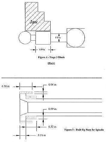
This had me scared for some time and actually caused the project to "go under the bench". When I finally tackled it, it presented no problem at all, apart from machining the actual spindle. Blindly following the instructions, I went out and bought a high tensile bolt, a material which I'd never machined before. This thing cost the planet and I couldn't find one with a head big enough to accommodate the spindle nose. However, looking at it, it seemed that the desired shape could be built up by loctiting on a sleeve which would be under compression when the nut was tightened. These pieces are shown in Figure 5...
Base
This part is straight sailing and only a real idiot could find something to stuff up here. Well, you guessed it. The final operation was to drill the base to take the pivot bolt for the tilting arm. By this time, I'd become so fixated with hitting the centre of any boss that I did not even consider that the distance of the hole above the main bore axis is more important than is a central hole in a boss that can't be seen when the device is assembled. The result is that when I tilt by arm counter clockwise, the bolt head that secures the rotating base strikes the base casting before full 30 degree rotating is reached. In fact, the limit on my Quorn is only 15 degrees. I can improve this by cutting into the base for the screw head. I will if this causes me grief. Oh well. (Addendum 2005: it did, but some milling of the base now allows 30 degrees in both directions).
Micrometer
The Book observes that manipulating the workhead with the right hand and applying the cut with the left is a natural way to use the machine, for right-handed operators. This means that the force applying the cut is all coming from the spring that keeps the front bar against the micrometer screw end. Any binding in the free movement of the front bar may result in it not advancing, then suddenly leaping into the wheel with a rush. I've found that even though my bar is tight (so far) and sometimes catches during static operation, this does not happen when the machine is running. I think the vibration overcomes the friction.
Rotating Base
Not too much to say about this except the once again, The Book is correct; a "D" bit will bore a strait and true hole, given a little start and frequent removals to clear the chips. In fact, it was all going so well, I got too adventurous and with 1/8" to go before brake-out, I ceased the bit in the hole. How many disasters can one blundering beginner have?
Work Head and Division Plate
Now you're going to be really surprised, as I completed this assembly with no disasters! Well, there is the case of the wandering degree scale punching on the division plate mentioned earlier, but that's just cosmetic and hardly noticeable anyway. The division plate is one place The Book makes no special mention except to just make it. Careful planning of the machining sequence will yield a plate that's concentric and complete all bar the knurling. I didn't want to grip the plate by the now finished scale area, so I used the split tapered collet and nut to secure it to a 1" diameter stub for knurling.
Tool Holding Spindles and Arbors
Oh no, you say, he can't possibly cock these up, they're just bars with holes in them! Well as usual, nothing is ever as simple as it seems. For me, the main use for a T&C grinder is going to be making lathe tooling. This requires (mostly) a spindle with a square hole in it. The Book gives two fabrication methods and two designs (4 combinations). I chose the one piece spindle construction (to be broached out using my handy-dandy Hemingway slot cutter attachment) with the cap screw nose, as opposed to the "no nose" and four grub screw design. Bad choice. I'll say it again, louder this time: don't make this design. On the surface, it seems better because the spindle does not have to be withdrawn from the workhead to access the screws. Unfortunately, it suffers from two major disadvantages.
Errors and Omissions
Overall, the editing job on The Book is quite good. There are a couple of omitted dimensions on the tailstock and a dimension mistake that is so obvious, you can't possibly get it wrong (Figure 33, page 37 calls out the bar beds as 5/16" GMS; they should be 5/8". The diameter of the spindle shaft is also wrong in my edition which is published by Tee Press). The machining instructions are quite adequate, but probably didn't anticipate a complete novice like me using them. All that said, in so large a project, there are some points that need to be brought to a builder's attention. As I mentioned earlier, you really need ten, not nine, large ball handles. That is, unless you are prepared to swap one handle between the standard work head and the spiraling work head. Using the long and drawn out method described earlier, all my large ball handles were made in an orgy of effort one Sunday, finishing in time to still mow the lawn, shower and relax surrounded by my ball handles, before the sun went down. Making just one additional blighter consumed an entire evening. It's much easier to do them as a production batch, but you need to know exactly how many to make first.
Conclusion
It's over, I enjoyed it, I learnt a lot and the tool is a joy to use. Would I do it again? Yes, certainly. There are many things that would come out better on the second one, but I don't have to. The key point is that a raw beginner can perform all the operations to build this machine on a 3-1/2" lathe (like the excellent Myford Super 7). I also used a drill press and a vertical milling slide for the Myford, but the latter is probably not mandatory. Next I plan to build a nice wooden base with a polished, removable dust cover and draws for the wheels and accessories. As mentioned earlier, I used a spreadsheet to track progress on the project. This not only helped me plan the raw material part list, but also gave me a running summary of progress. I found this really encouraging as I could progress was being made, even if it didn't seem like it. If you want, you can download a copy of this spreadsheet from here. I hope it helps when you take the plunge and build your own.
Additional Information:
Pipworth Farm, Pipworth Lane
Ekington, Sheffield S31 9EV
England
P.O Box 785
Kenmore 4069
Australia
Web Site: http://www.hobbymechanics.com.au
Email John at [email protected]
Rev (2): 2003-11-27