GHT UPT
Construction Log:
Arms
Created: November 2006
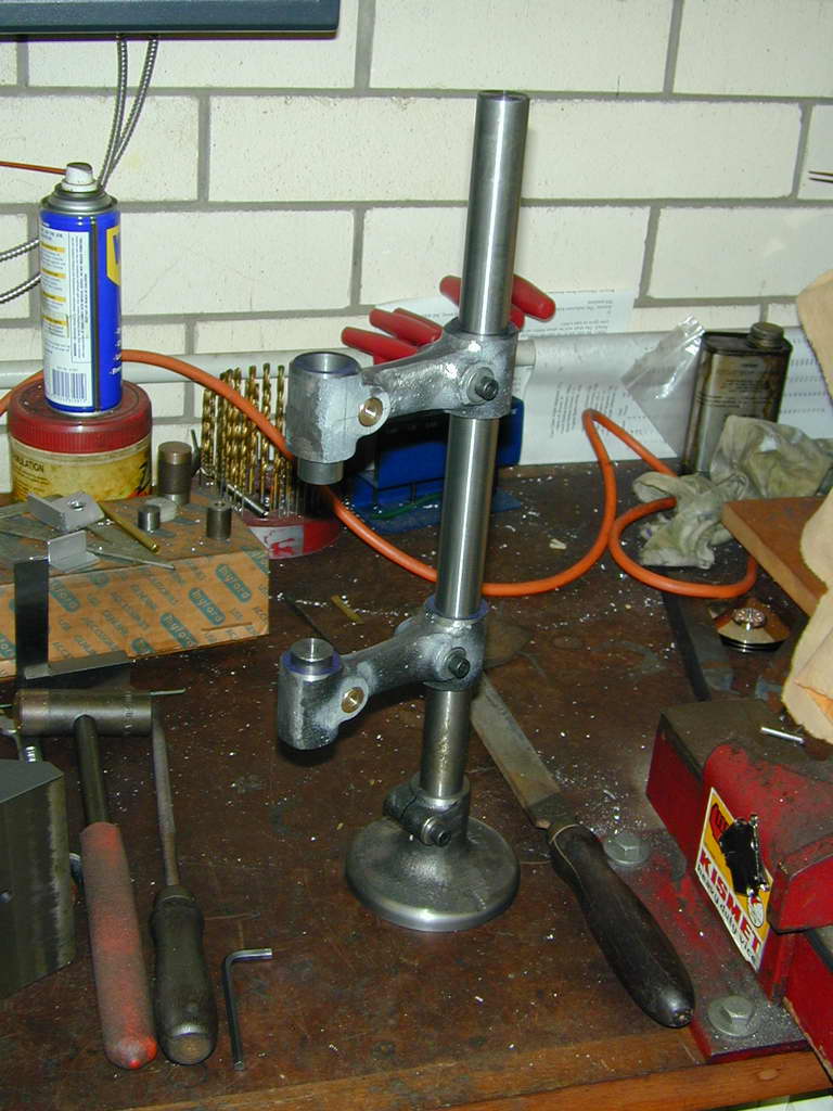
The critical thing for the arms is making the bores parallel to each other, a close sliding fit on the pillar, and exactly the same distance apart. This is relatively easy. The photo shows the trial assembly after boring the arms. It is most satisfying to bring the arms into contact, then drop a 3/4" diameter slug into the top arm and be able to push it through both bores as if they were one.
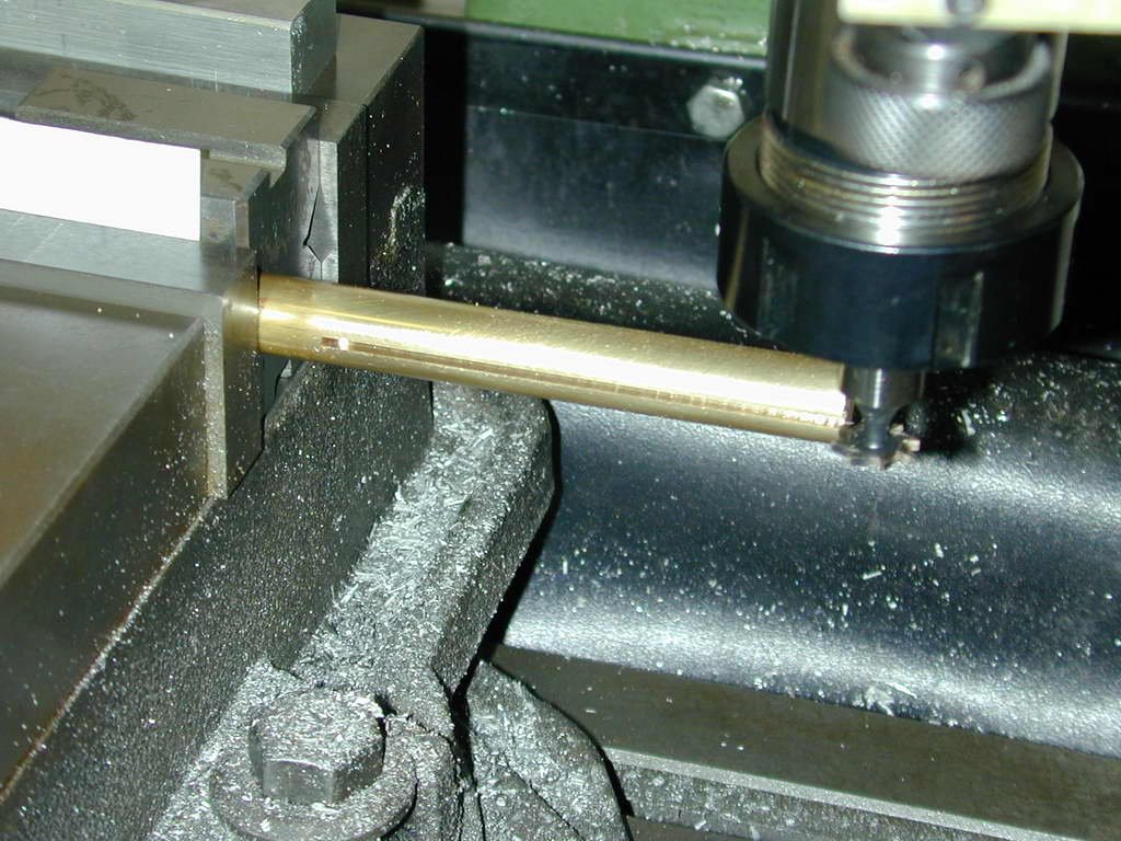 Photo 6 |
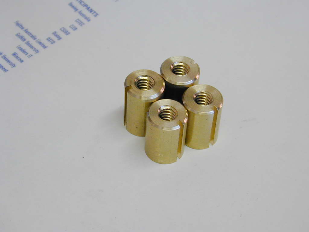 Photo 7 |
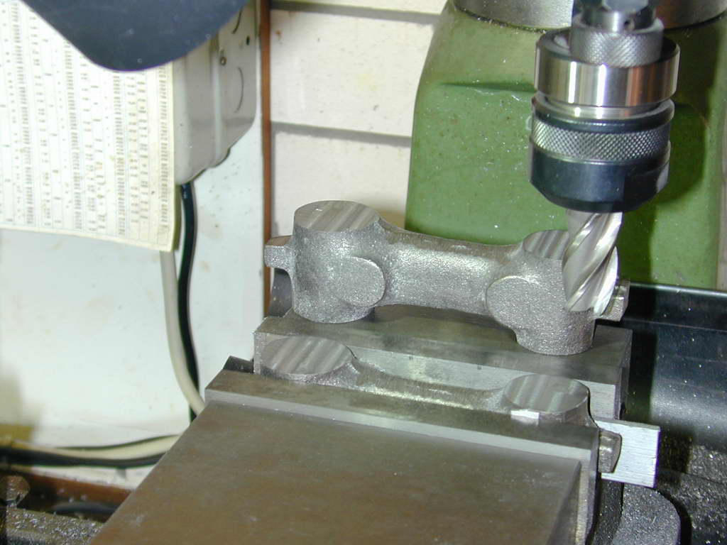 Photo 8 |
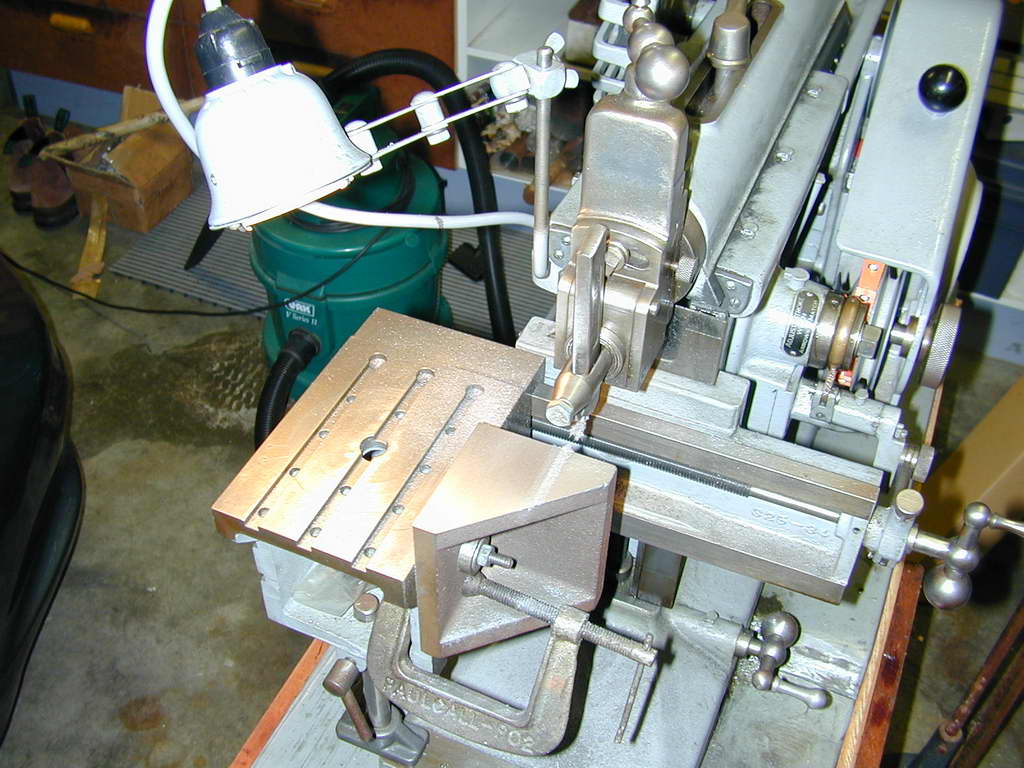 Photo 9 |
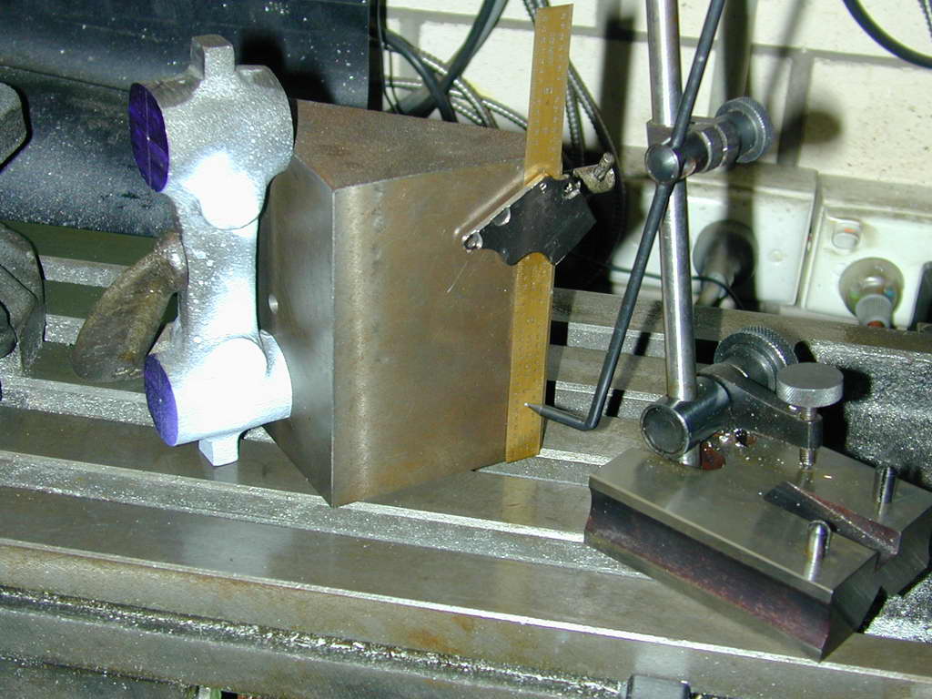 Photo 10 |
Marking out is important here, especially getting the centers of the cotters in the right place relative to the bores in the arms. GHT's photos show a surface plate, precision ground box fixture, and Vernier height gauge being used. You may not have all these valuable aids—I sure don't. Photo 9 shows a shop-machined angle plate being trued on the shaper to substitute for the box fixture. This allows an arm to be aligned with its scribed axis vertical and the bore center-pop picked up with a scriber block. In Photo 10, a 6" rule has been clamped to the fixture with a magnet salvaged from a dead hard disk drive so that a major division aligns with the scriber pointer. The pointer can now be raised against the ruler by the right number of sixteenths to scribe the datum for the cotter. This will be within 5 to 10 thou of where it should be, which is good enough.
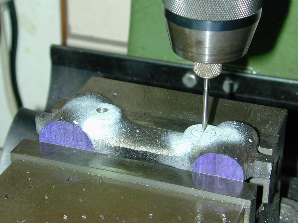 Photo 11 |
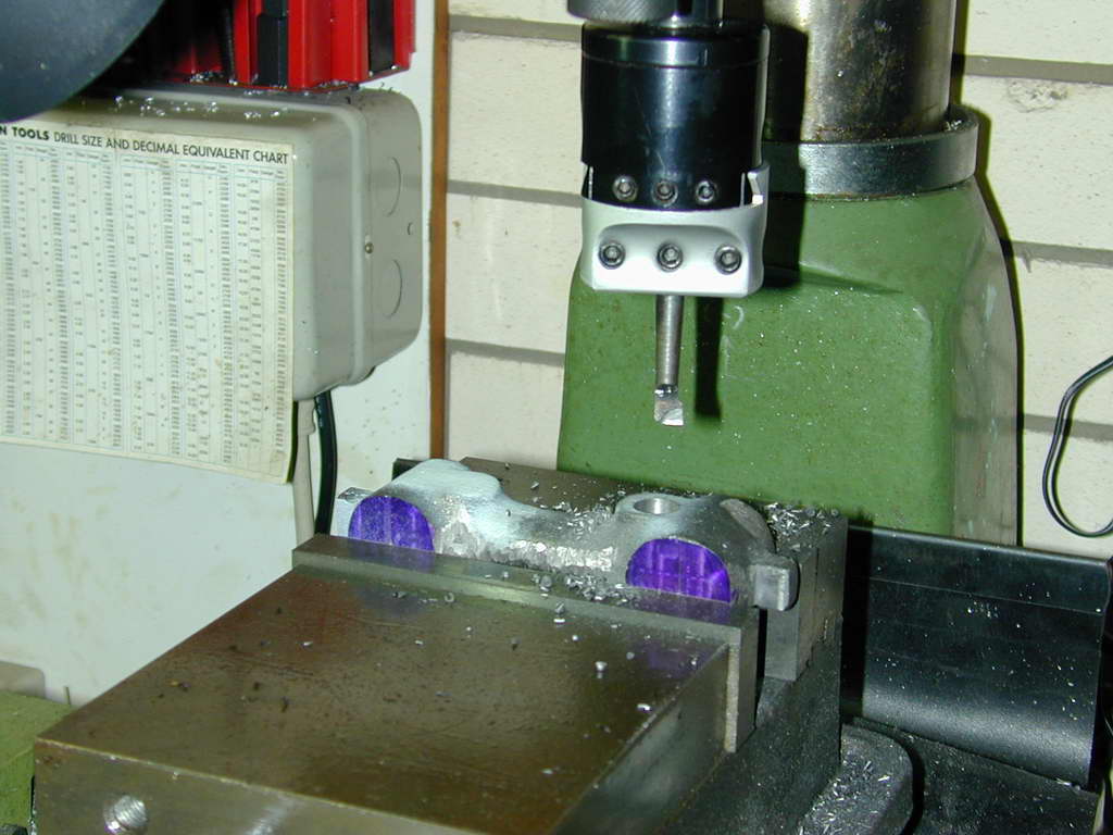 Photo 12 |
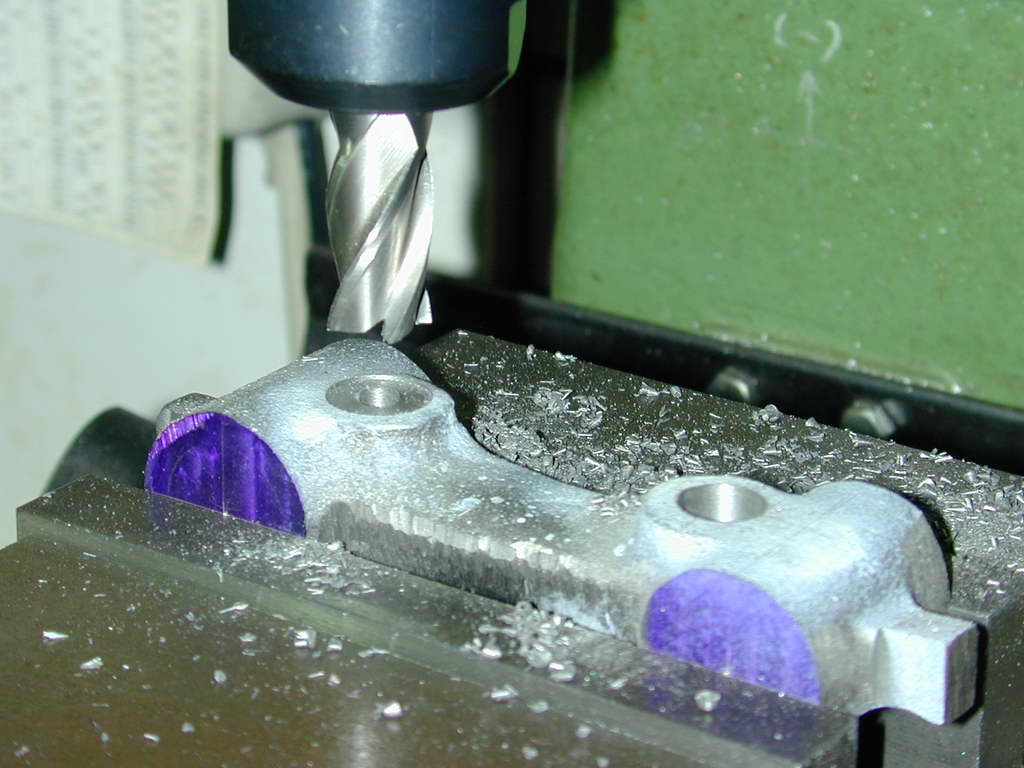 Photo 13 |
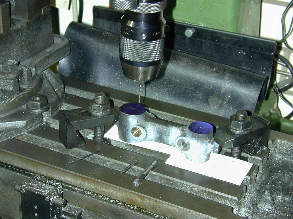 Photo 14 |
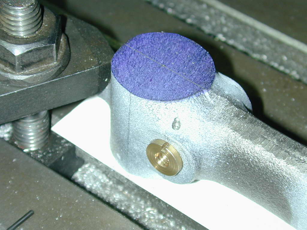 Photo 15 |
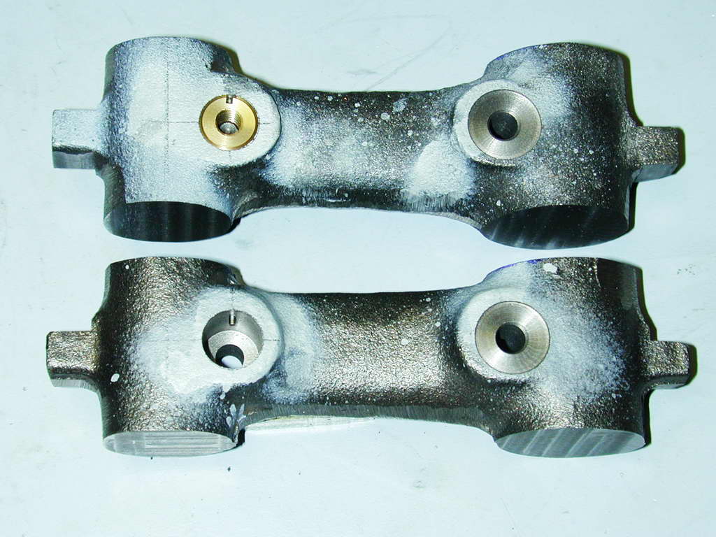 Photo 16 |
The bores for the cotters need to be a close fit, so they are finished by boring. In Photos 11, 12 and 13, the arms have been aligned in the mill vice on the scribed lines through the bore centers. The hole for the 1/16" pin that aligns the cotter by the slot cut with a #1 Woodruff cutter in Photo 6, enters on an angled part of the Hemingway castings. You will never be able to start the drill accurately without milling a flat first, as seen in Photos 14 and 15. The alignment for the drill can be picked up from the slot in the cotter itself. The cotter needs to be firmly clamped in place before the arm can be bored.
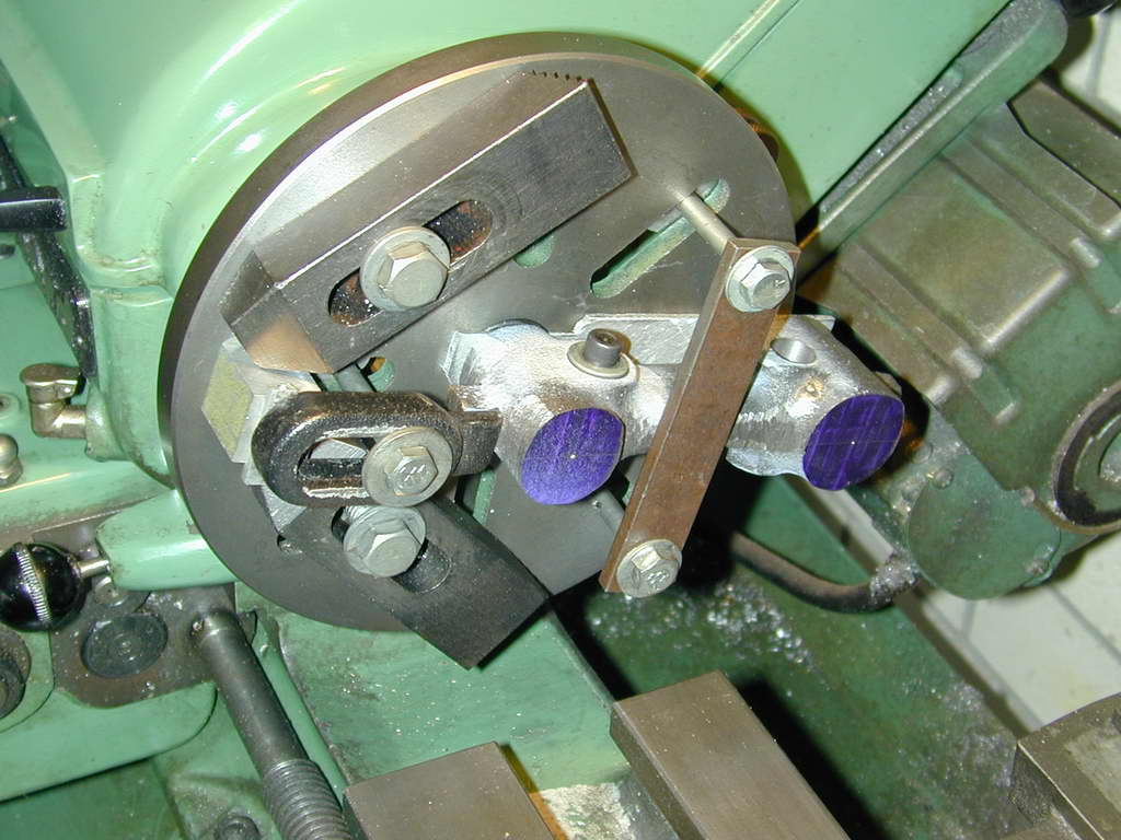 Photo 17 |
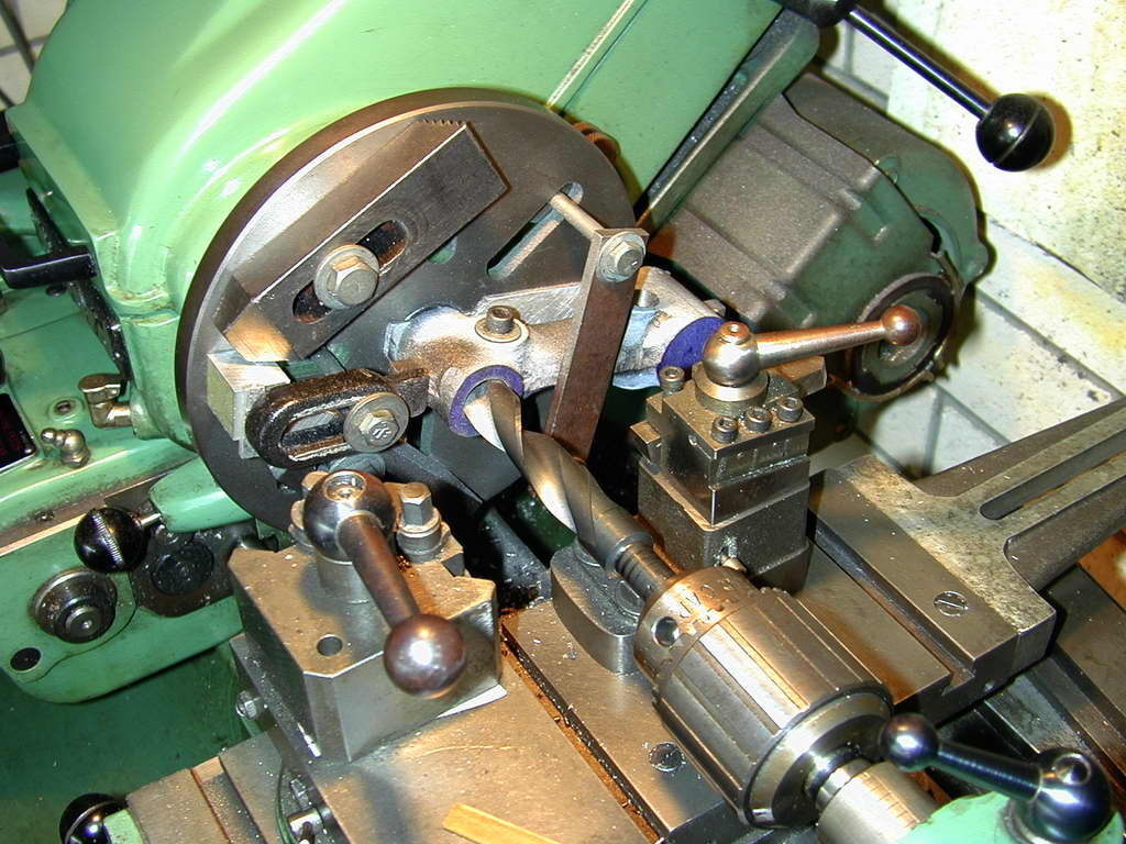 Photo 18 |
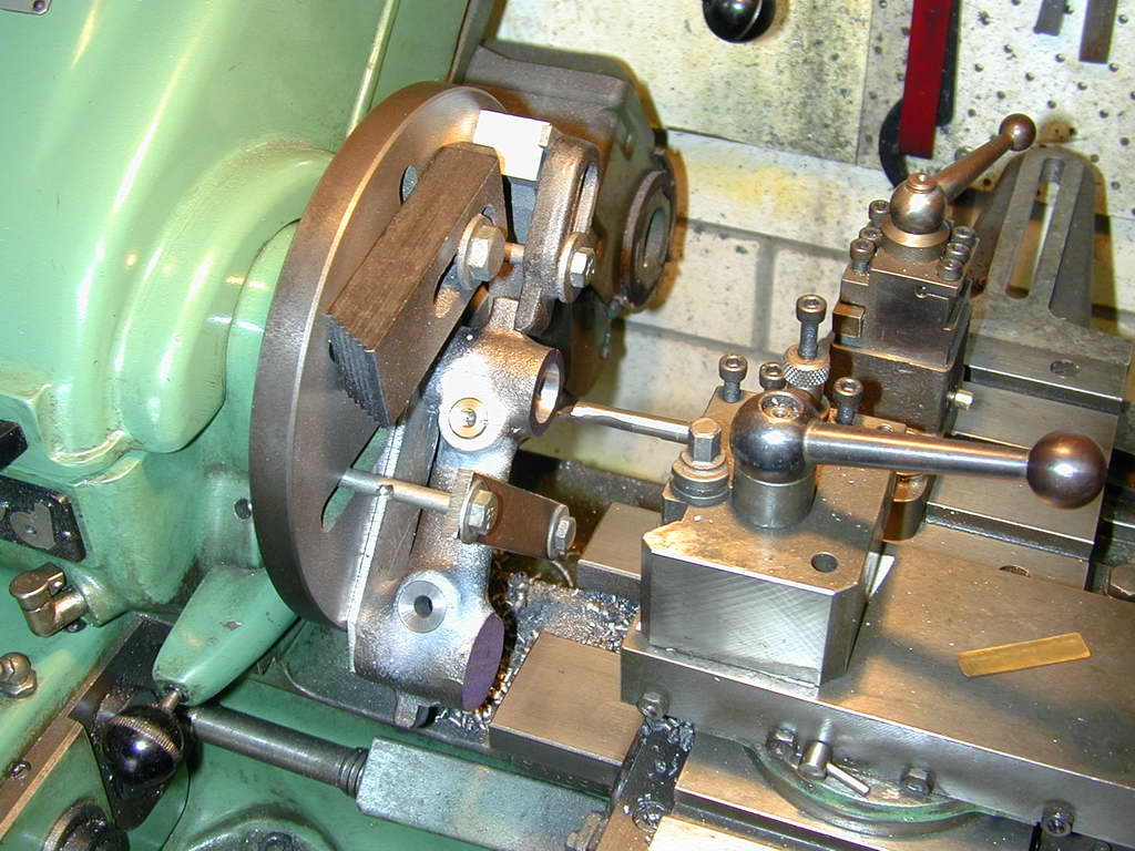 Photo 19 |
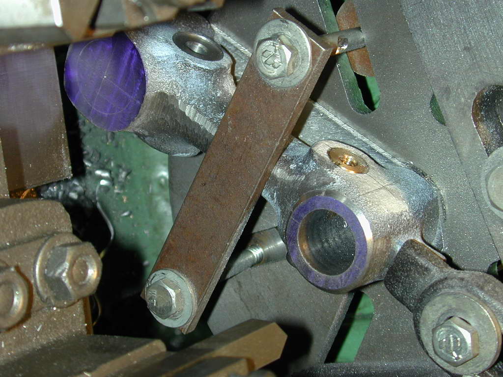 Photo 20 |
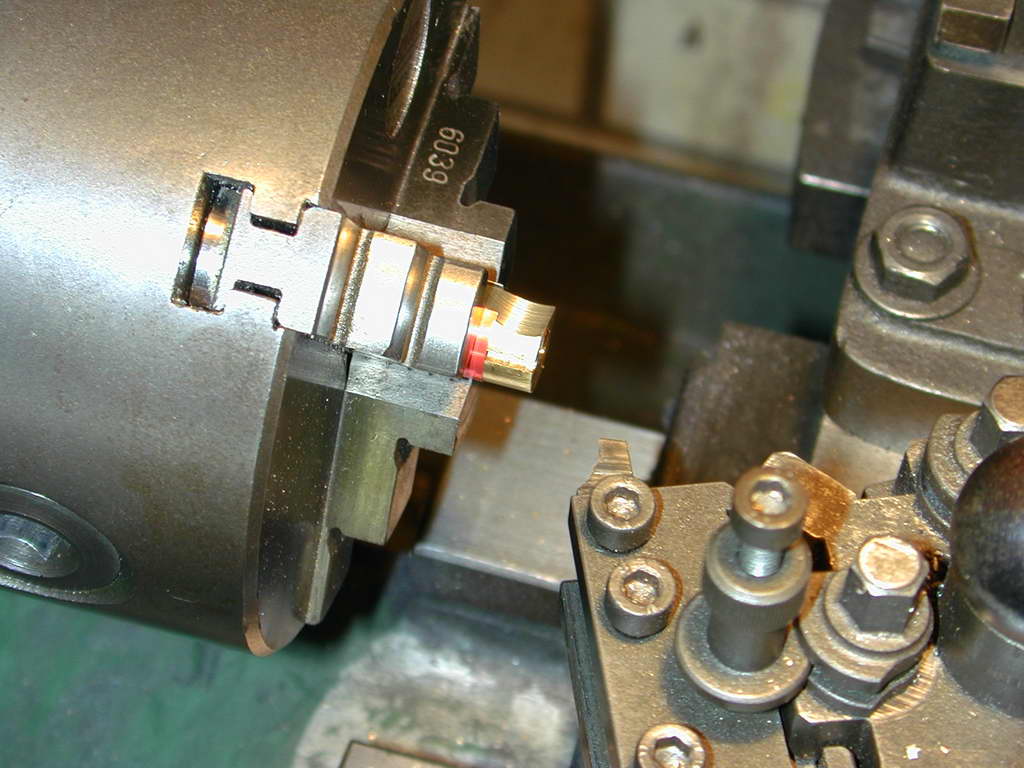 Photo 21 |
Photos 17 through 20 show an arm being bored 0.750" with the center-pop centered just by holding the arm against a plate of sacrificial material on the faceplate by bringing up a tailstock center into the dimple. This will be well within 10 thou of where it needs to be and the location of the first hole is not that significant. Photo 21 shows the cotter being faced back to remove the concavity from the turned end so that it can forever after act as a clamp against a close fitting bar in the bore.
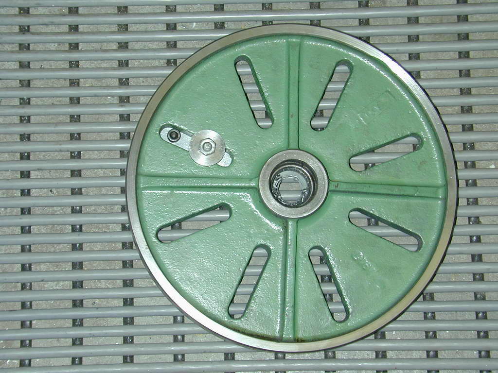 Photo 22 |
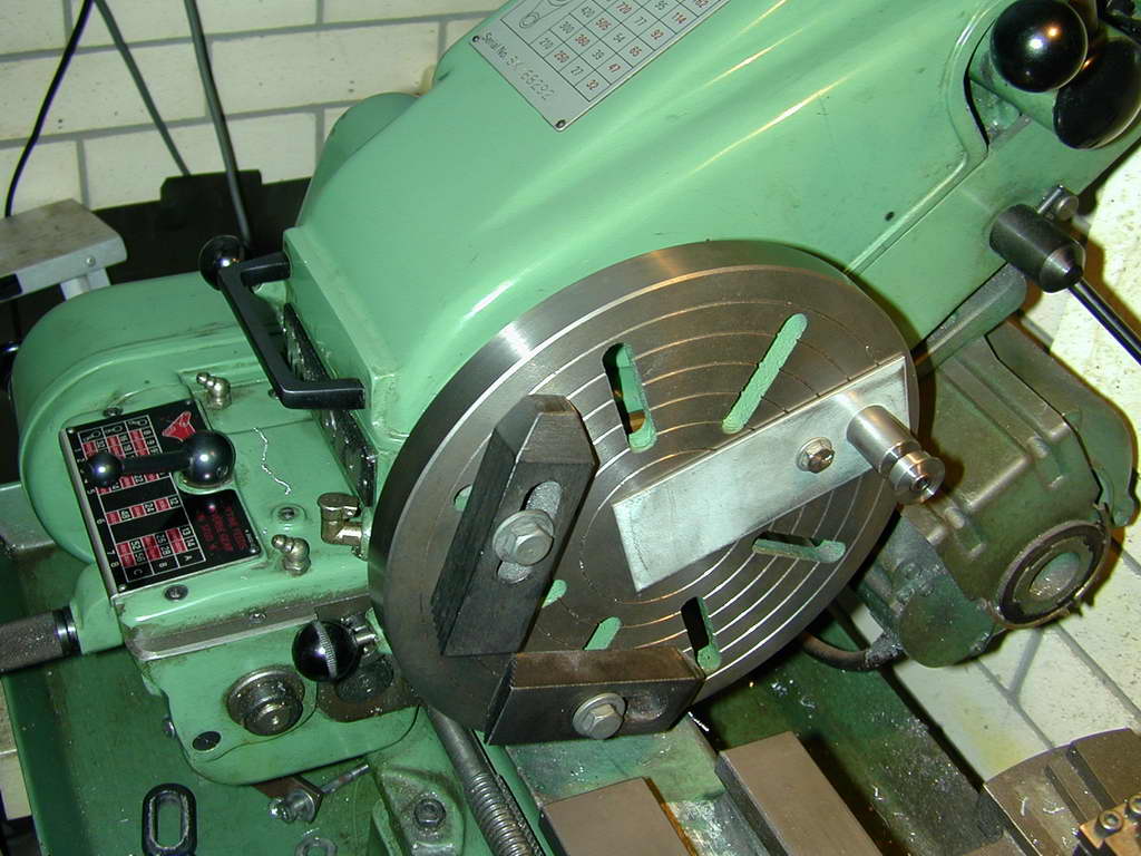 Photo 23 |
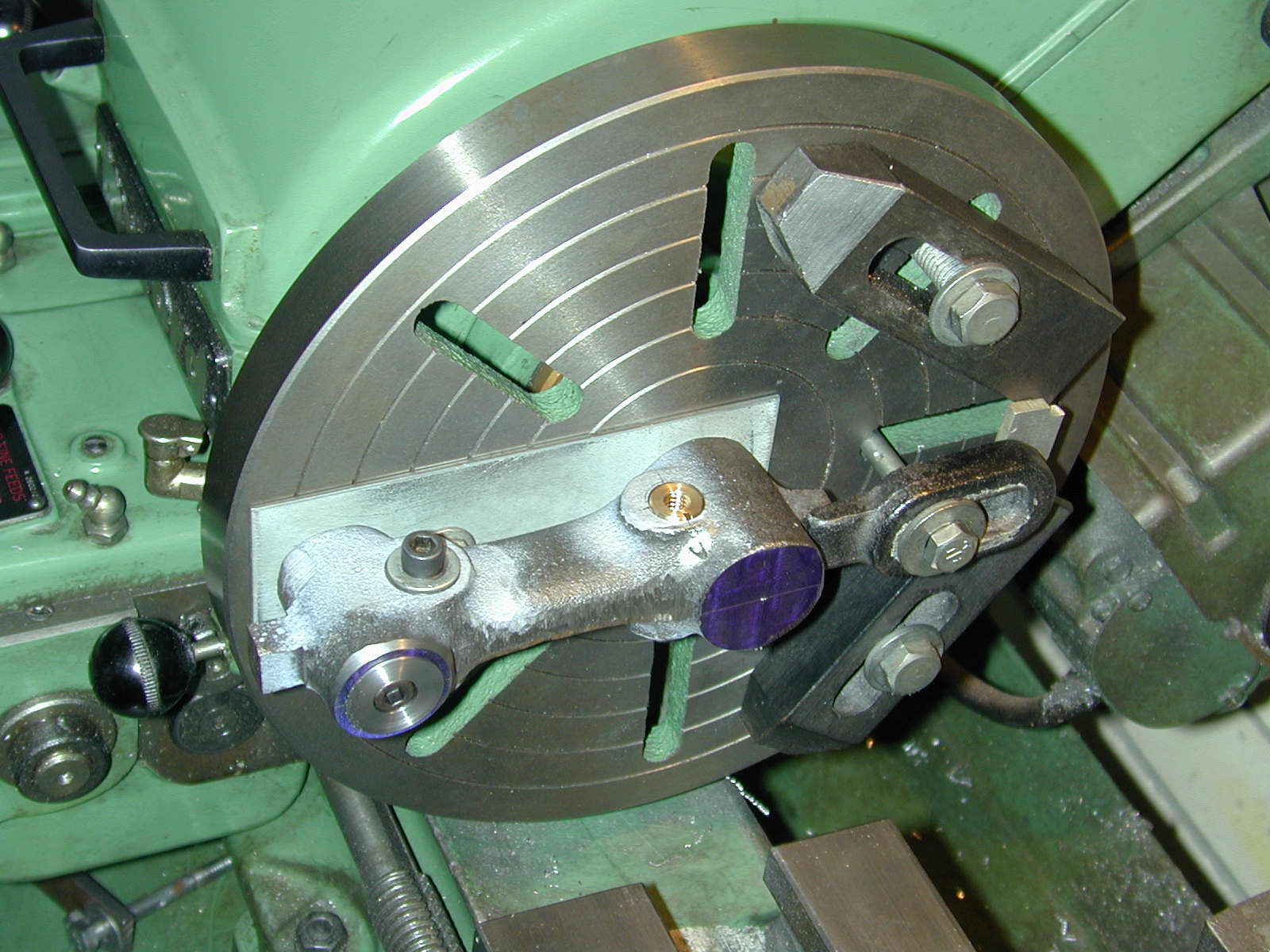 Photo 24 |
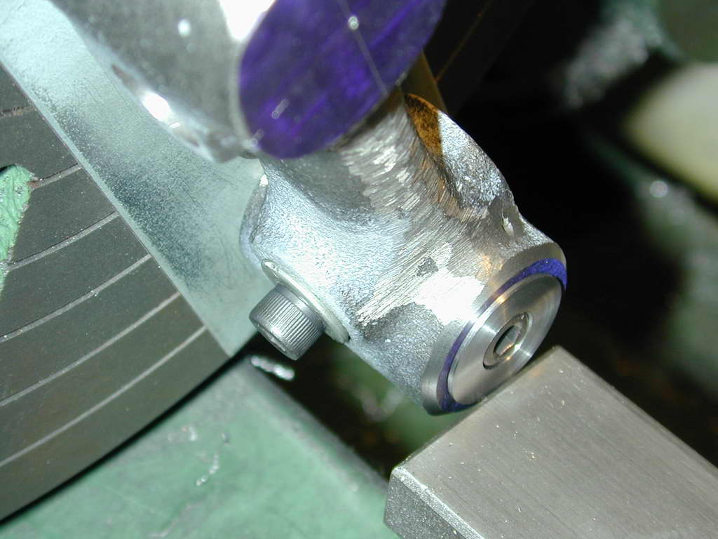 Photo 25 |
Aligning the arms to get the bores spaced the same distance apart is simple, just follow GHT's instructions. I had to use the large Myford faceplate to mount this jig (Photos 22 to 24). As you can see in Photo 25, we are right on the limit for working in the gap of the Super 7B. The cap with the recessed hole for the socket head screw had to be thinned from that shown on the drawings. Either the Myford gap has shrunk since GHT's day, or their big faceplate has got thicker (I suspect the latter). The cap just assures the arm is pulled firmly onto the sacrificial jig plate. The real work of holding it there is done by the cotter on the outer end, and a faceplate clamp against the cast-in jigging piece on the inner end. The arms can then be bored to a close fit on the pillar.
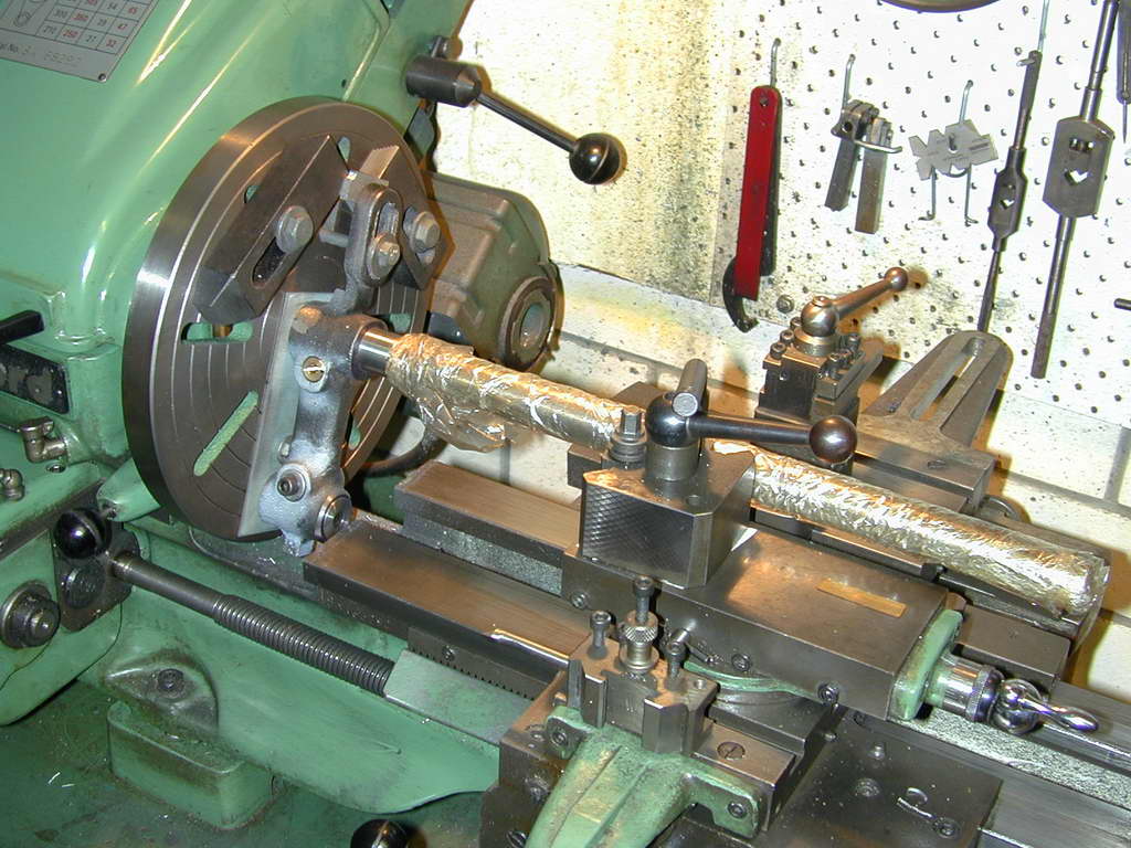 Photo 26 |

| Back: Base and Pillar | UPT Index | Next: Ball Handles |
 Model Engine News Home
This page designed to look best when using anything but IE!
Please submit all questions and comments to
[email protected]
Copyright (c) Ronald A Chernich, 2006. All rights reserved worldwide.