GHT UPT
Construction Log:
Base and Pillar
Created: November 2006
Nothing worth talking about on the base except not to do as I did and slit it per the drawings for a clamp screw (Photo 3). Cotters, as used in the arms, work much better, and they are not a lot of extra work.
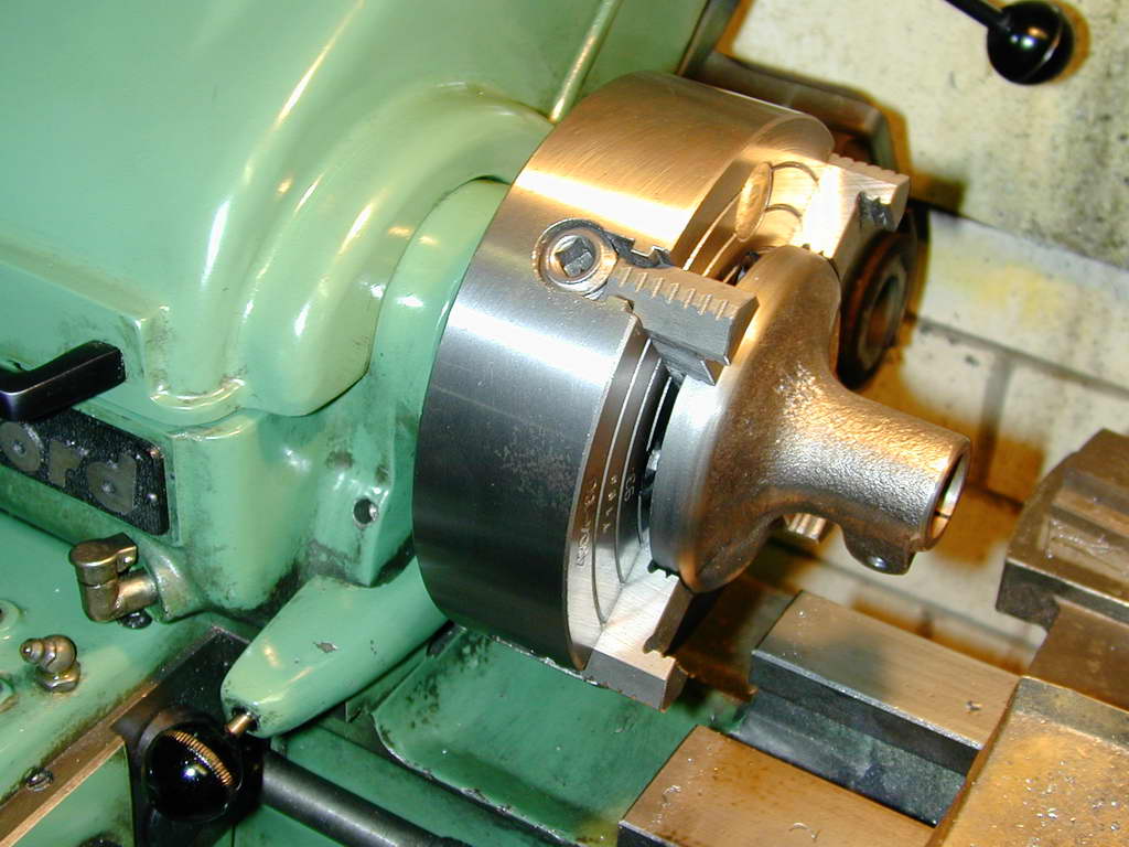 Photo 1 |
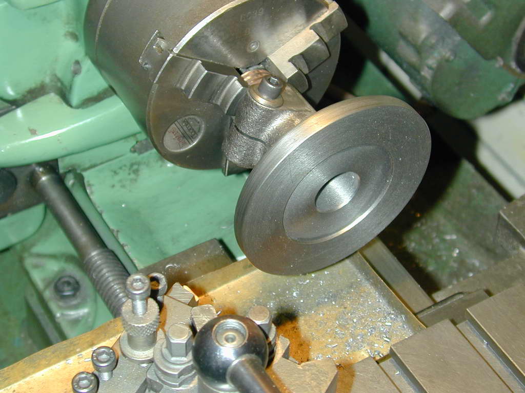 Photo 2 |
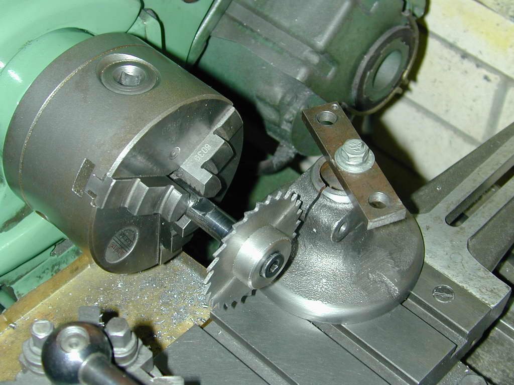 Photo 3 |
The 0.825" PGMS pillar needs to be faced on one end and reduced to 3/4" diameter on the other so that the table stem and pillar are interchangeable in the base. Photo 4 shows how to set the fixed steady against the work right next to the chuck so it will require next to no adjustment when moved to the far end. Use a DTI to get run-out less than say 0.002". It's not all that critical, but accurate work is a justification unto itself, and badly centered work will tend to work its way out of the chuck. As you can see, this is about the limit for the length of work that the Myford can handle.
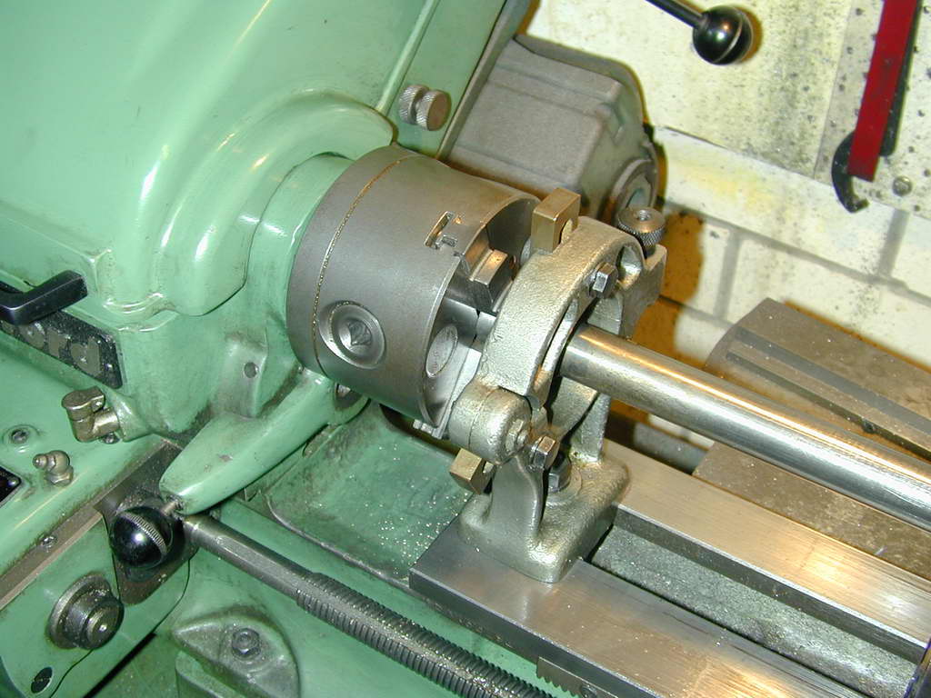 Photo 4 |
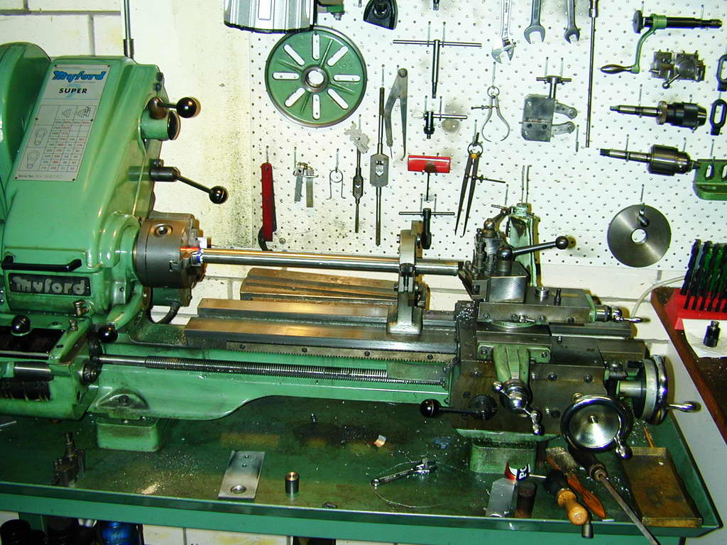 Photo 5 |
The three mounting holes for the base can now be drilled and counter-bored (no photo). You might like to space them so that the base can be clamped to your mill table via the T-slots. On my awful "RF40" mill-drill, this is a PCD (Pitch Circle Diameter) of exactly 2 inches.
And yes, photos 1 to 3 are "posed" after the event. The actual rim turning is not done until the setup of Photo 2. Hope that you can forgive me for being too lazy to walk back inside and get the camera when the actual work was being done...

| UPT Index | Next: Arms |

This page designed to look best when using anything but IE!
Please submit all questions and comments to
[email protected]
Copyright (c) Ronald A Chernich, 2006. All rights reserved worldwide.