Model Engine Gallery Page 15
Click on the images to view them larger size.
|
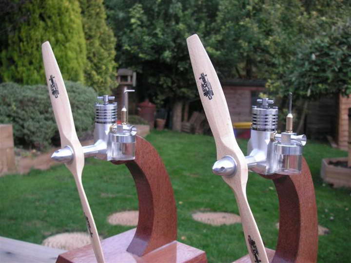
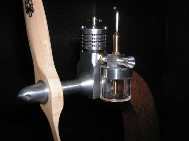
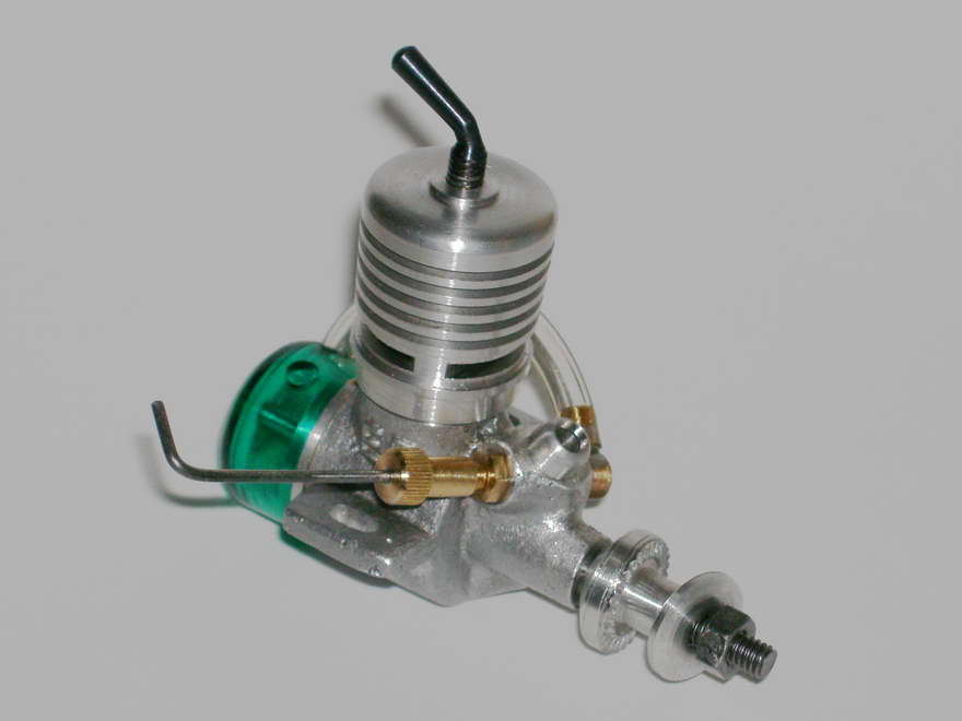
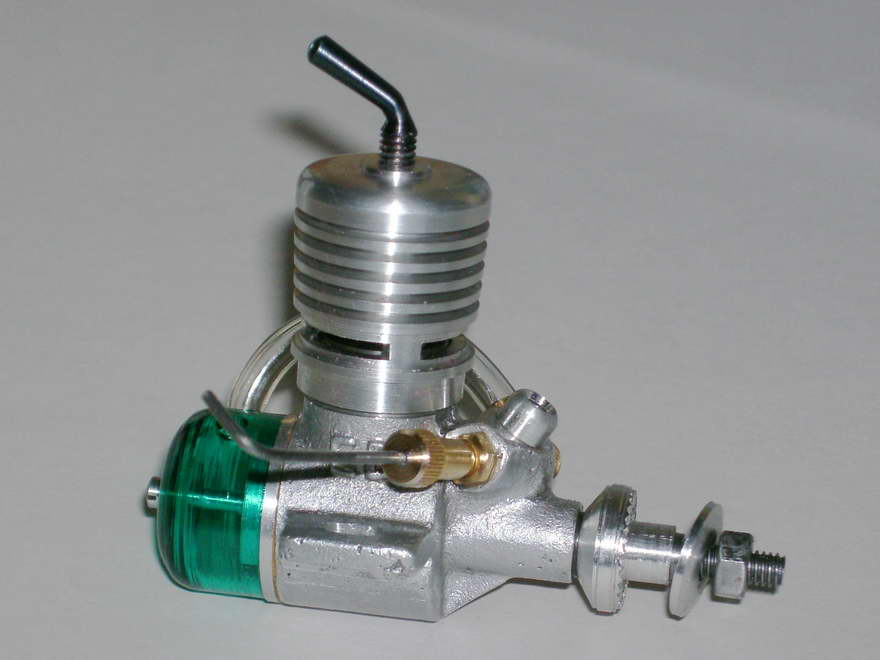
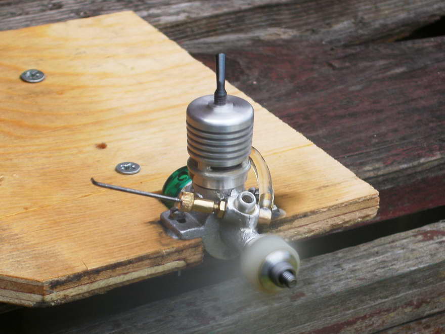
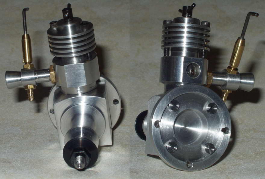
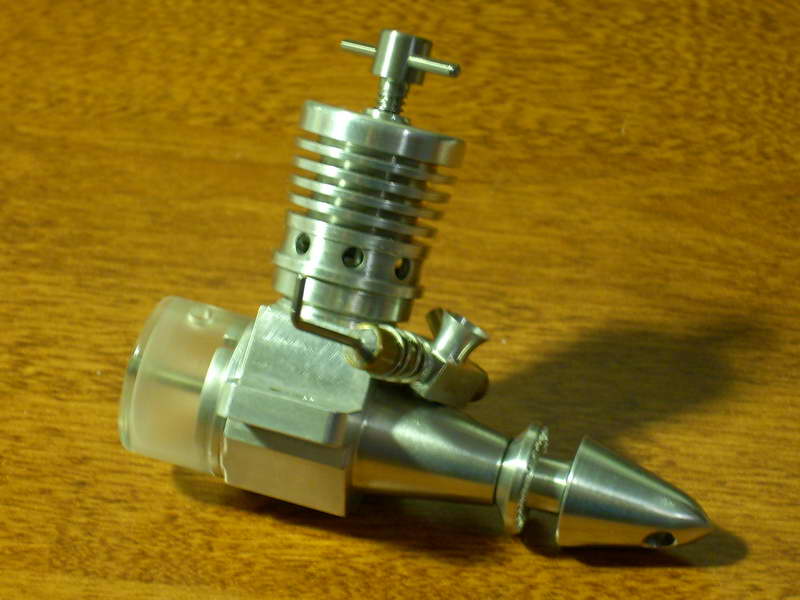
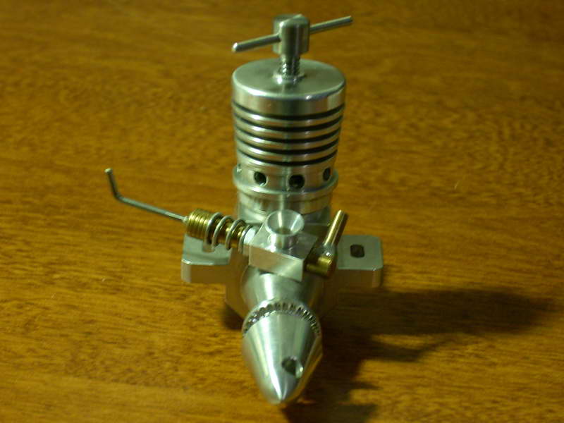
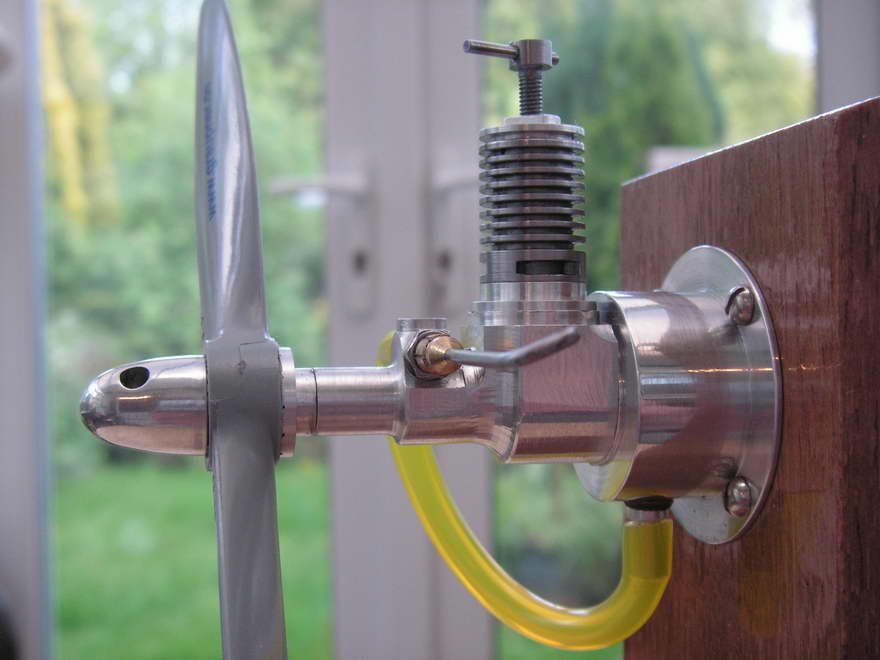
Adam Mills (Surrey, England, and no relation  ) is the builder of these Midges, or should that be Midgii? He build them from our MBI plans on a 7x12 mini lathe and reports that both start easily and run well. I especially like the neatly turned and clear fuel tank, the clean, minimal soldering job on the needle thimble, and attention to small detail, like the chamfered edges on the Tommy-bar. The wooden display stands are a nice touch too. I've lost track of the number of ML Midge plan sets we've sent out, but it is really gratifying to see the number of completed engine photos that come back in return. Mark Lubbock's little design must be approaching the "most built" model engine of the modern era. ) is the builder of these Midges, or should that be Midgii? He build them from our MBI plans on a 7x12 mini lathe and reports that both start easily and run well. I especially like the neatly turned and clear fuel tank, the clean, minimal soldering job on the needle thimble, and attention to small detail, like the chamfered edges on the Tommy-bar. The wooden display stands are a nice touch too. I've lost track of the number of ML Midge plan sets we've sent out, but it is really gratifying to see the number of completed engine photos that come back in return. Mark Lubbock's little design must be approaching the "most built" model engine of the modern era.
|
|||||||||||||||||||
|
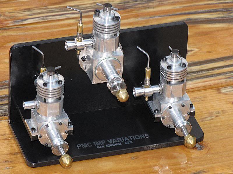
We've see Gail Graham's PMC Imp before, but now it's had pups. Here are three engines Gail (New Mexico, USA) built from the Members' Free Plan set for the PMC Imp. He has documented the process in a very comprehensive, well illustrated series which you can read on the Home Model Engine Machinist forum. The engine in the center is very close to "as drawn", which is close to the commercial versions. The ones on either side add beam mounting and nice cosmetic enhancements. Gail has also opted for a Taipan-like splined prop driver fit. The forum posts include videos of CNC profiling the lower crankcase and the finished the engine running happily. | |||||||||||||||||||
|
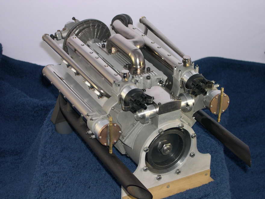
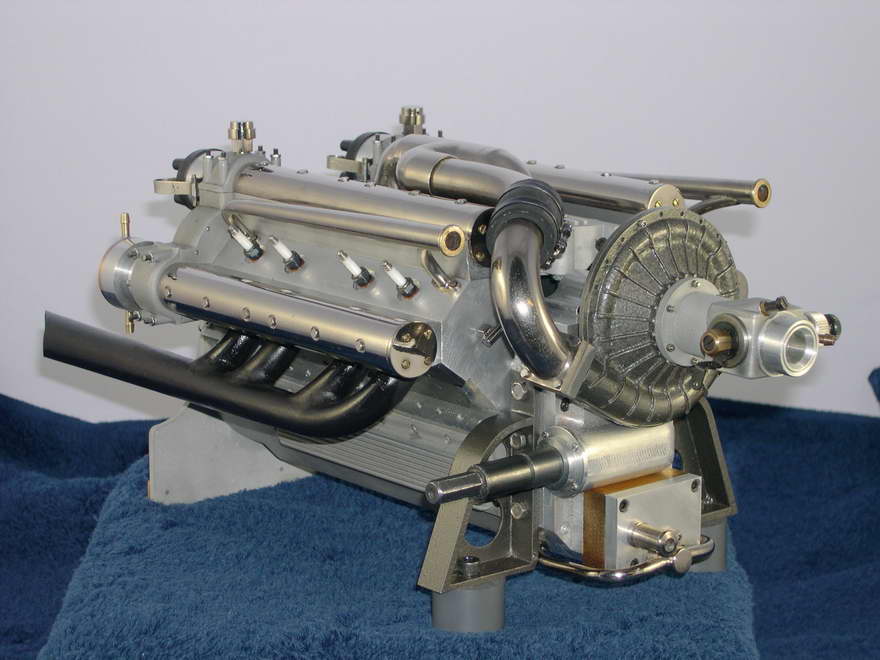
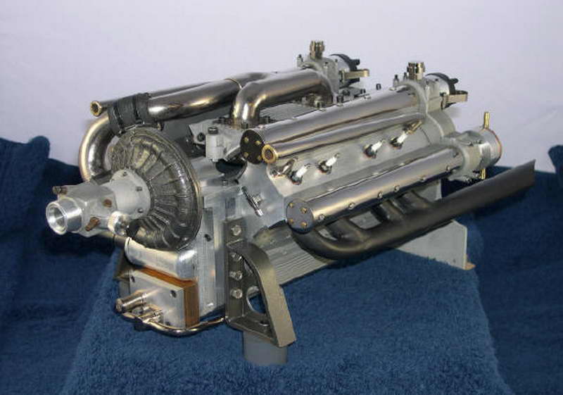
This work of art is a quarter scale Novi V8 being built by Ron Colonna. It features dual overhead cams on each cylinder bank, gear driven along with the water and oil pumps. Bore and stroke are both 3/4" for a total displacement of 2.651 cuin (43.45cc). The supercharger is geared to over five times engine speed and ignition is by sparking plug. The engine is fully machined from the solid. You, you read right. I asked Ron about the blower housing and here is his reply:
Ron, that blower housing was a lot of work. The scroll on the outside of both halves started out as a steel rod machined to the calculated taper using a taper attachment on my nine inch South Bend lathe. It was then sawn in half lengthwise, and each half bent to the involute on a steel plate using stop pins as a guide. The shape was bent hot with a lot of hammering to keep it flat against the plate. Each half was then sweat silver soldered to it's respective cover plate using sheet silver solder sandwiched between the parts. The inside of each half was machined to the involute shape using a ball shaped cutter. Of course the width and depth of this groove changes as you work around the scroll. The width was taken care of by simple manipulation of the X and Y axis of the mill table. The uniform change in depth was taken care of using left and right hand fixtures equipped with left and right hand jack screws under the plates. The screws were cut with a 6 threads to the inch pitch and with a rod welded to the plate, the fixture was rotated by hand for one complete turn. The rotation lifted the fixture into the cutter as the work was rotated, deepening the cut through the rotation. CNC would have made it a lot easier but I don't have the machinery to do it. Heck, I don't even own a DRO! The cooling fins on the outside are all silver soldered on using wire with a square cross section to mimic those on the full sized engine. I originally thought of making a wooden pattern and having the housing cast in aluminium, but it wouldn't have been any easier to do. I'm only building the one engine. The steel housing is a lot heavier than it should be, but then weight doesn't matter except for airplane engines anyway. I'm hoping this one never leaves the ground! The other techniques used on things like the crankcase, camshaft covers, etc, etc. are spelled out in my book on building the 270 Offy.
|
|||||||||||||||||||
|
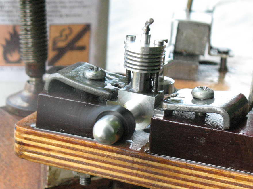
Here's a Mk II ED Baby made from MBI Words and Music and Roger Schroeder's Classic Model Engine casting set by Jim Frew (Dorset, UK). Jim confessed to doing the piston three times and the crankshaft twice, but there's no shame in that. Small diesels are a big challenge to any model engineer as getting the right piston and liner fit is much harder than it is on larger engines, and ay 0.46cc, the Baby is about as small as it gets. Jim's Mk II will turn a 7x4 and is pictured running with a 6x4. He has used Bert Streigler's tip of sacrificing a green handled screwdriver to the cause of an accurate reproduction fuel tank that looks just like the real thing. Roger and I get a big kick out of seeing pictures like this and hearing how Jim has had to wait 53 years from lusting after the ED Baby on his local model shop shelf to building one for himself. There are few thrills better than this. An undaunted by all those pistons, Jim is now thinking about making another, the Mk I "port-hole" exhaust model this time. | |||||||||||||||||||
|
And here's another successful miniature diesel built from the MBI Plans Catalogue, a Clanford Clan, made by Model Engine News Member, Mark Lester (UK). Mark rather sheepishly wrote that his little Clan took three years to make, but what matters is the end result and Mark has every right to be proud to have built a running example of a very difficult subject. The little Clan is a mere 0.24cc and is not a great design, requiring both fine machining and fitting, plus very careful assembly. Friction is the enemy of tiny engines and the two head long bolts that clamp the liner between head and case make it easy to pull the liner out of alignment. Mark has kindly provided some notes on building his Clan, including how he finally achieved the liner/piston fit required which is equally applicable to any really small engine. Read about them on the Building the Clanford Clan page. | |||||||||||||||||||
|
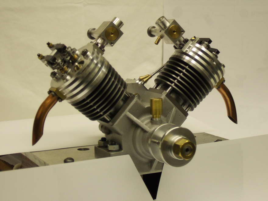
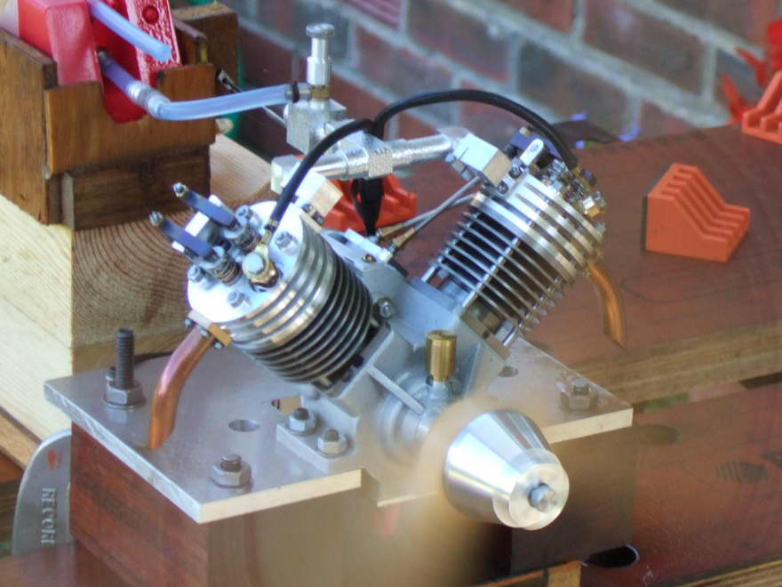
This much modified 90° Chenery V-twin is the work of John Beddard (UK). It has been under development for a while as John works methodically through the improvements and associated problems. He experienced a seizure of the shaft in the plain, phospher-bronze bush, so replaced it with an oilite one which appears to have cured that problem. Next step will be to replace the single carby seen feeding the cylinders in the running shot with dual, coupled units. Incidentally, if you think you've seen his name in these pages before, you have! Take a look towards the end of Graham Meeks' Cam Making Made Easy piece where you'll see the cam shaft for John's engine under construction. John was instrumental in bringing Graham's work to these pages. | |||||||||||||||||||
|
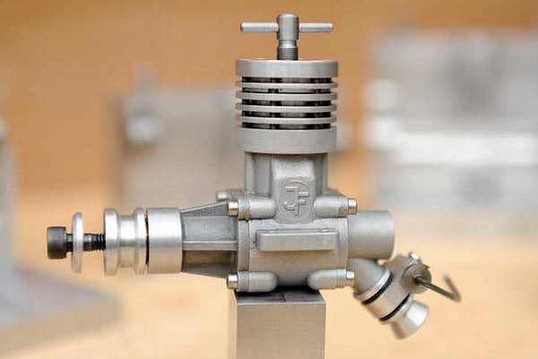
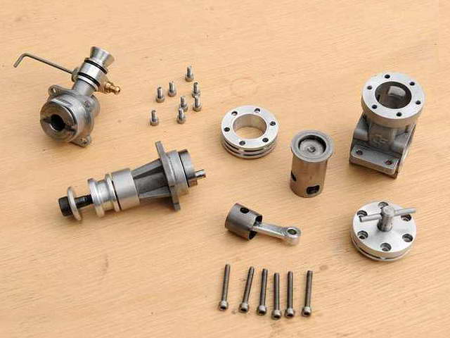
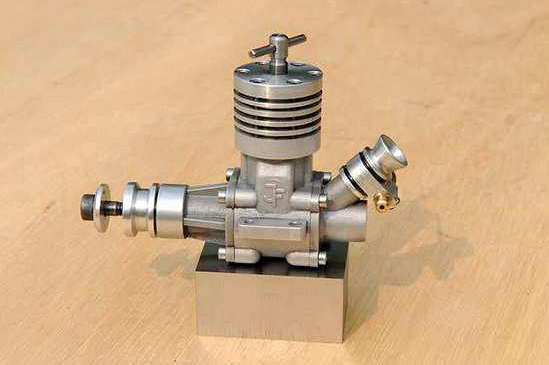
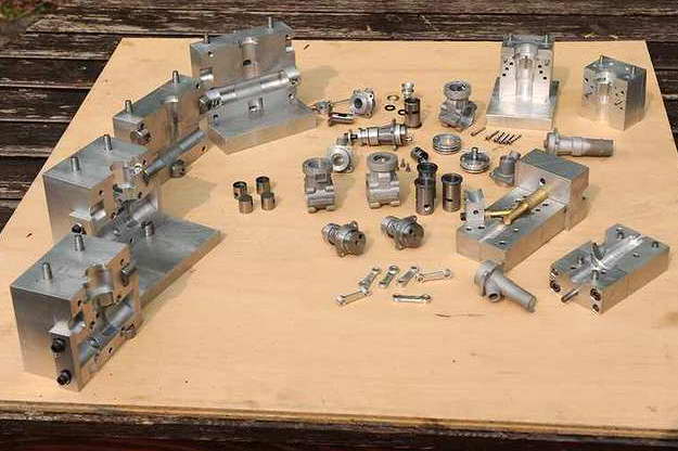
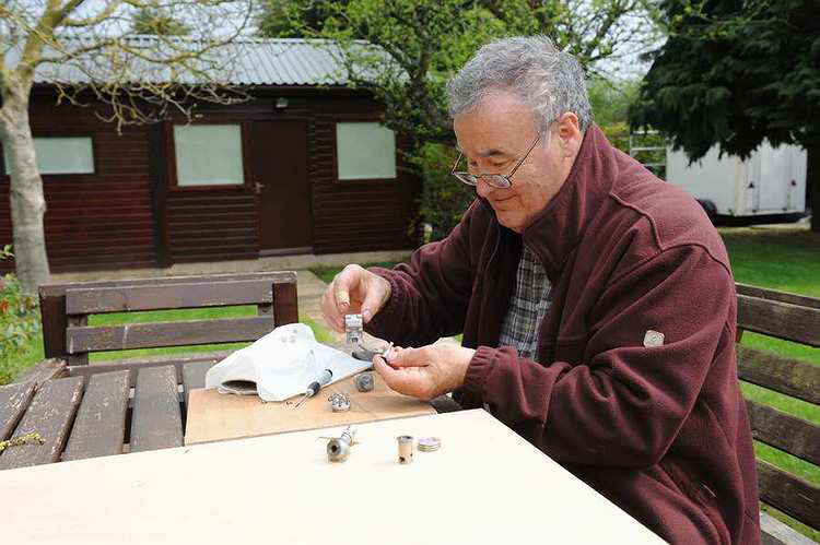
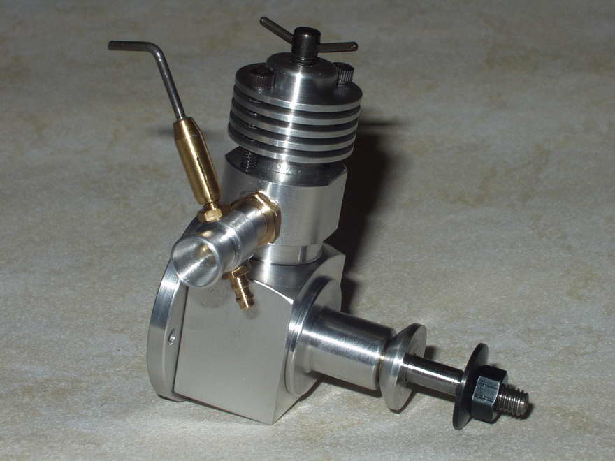
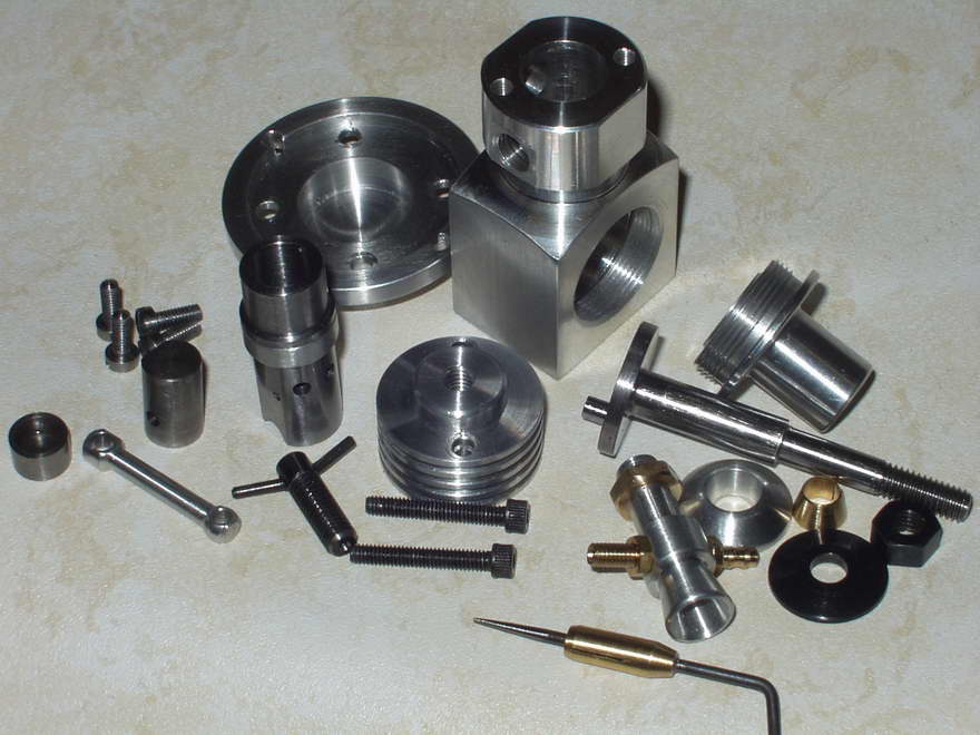
On Page 11, there are a few picture of the very, very professional lost-wax castings produced from dies made by John Feeney (UK) for his award winning boxer twin. Well John has sent in some details and pictures of his latest engine project. The original engine design was done in 1980 as a rear exhaust engine using a gravity die cast crankcase. John confesses that this project was not successful as he could not sort out the plaster cores to form the "inside". But after making wax dies for the Tempest Twin, he revisited the project and had a few waxes made in the old 1.5 gravity die. From these, his local foundry produced a few sets of excellent castings. From these, he has built a couple of engines using crankshaft, piston liner, etc from the abandoned 1980's project. Next, he decided to redesign with side exhaust, and three part crankcase, requiring the fabrication of new wax dies. This took a mere three years! The engines are now finished and run quite well. Having flown a 1.5cc engine, John is part way to completing a 2.0cc version and has enough castings for two more. He reports that if all goes to plan, when satisfied with performance, he will make any necessary modifications to the wax dies and get a few more casting sets made. Note the reversible inlet orientation, similar to the Burford/Doonside Sesqui. It's not obvious from the photos, but the design is not exactly a small engine and is probably optimum as a 2.0cc rather than the current 1.5cc version.
MEN asked John if he could provide some figures for RPM using the APC props Gordon Cornell used when measuring performance of the Super Fury Replica (see here). The results shows a most similar result:
These pictures were taken John's modeller friend, John Bowman. |
|||||||||||||||||||
|
Here's Richard Jackson's rendition of the PMC IMP, constructed from the first MEN Members' Free Plan, issued with the December 2005 issue. Ken Croft —with some justification—dubbed the production IMP ...most horrible.., but that does not prevent good running examples being made from our plan simply by applying the care and attention absent in the originals. Richard's variations on the design were to screw and glue the front bearing into the case proper rather than relying on glue alone, and to increase the stroke from 0.488 to 0.500 inch. This increases the displacement from 0.619cc to 0.635cc. The IMP runs well and seems to go on for ever on a very tiny amount of fuel.
In his email that accompanied the photos, Richard observed that the thick liner would support boring out from 0.318" to 0.375", although this would require that the transfer be cut into the crankcase rather than into the liner as it is now. This would increase the displacement to 0.905cc (the displacement varies as the square of the bore, so you get more change from an increase in bore than from the stroke). But what about the effect of bore/stroke ratio and timing, you ask? Well that's the great thing about making small engines like this. The cost of material is small and provided you make just one change at a time, you stand a chance of being able to measure the effect of the change. Even better if you use a tool like ICE to predict the effect of such a change, and are then able to confirm it (or come up with a theory as to why you could not |
|||||||||||||||||||
|
This is an ED Baby 0.46cc replica built from barstock using the plans published in the MBI Plan Book, Second Edition. It was made by Jered Johnson (Springfield, Ohio, USA). Note that Jered has not attempted to carve the venturi assembly integral with the case, instead he has glued it in as a separate component as featured in the 2.5cc Owen Mate and 0.1cc Nano. I especially like the way Jered has not attempted to replicate a casting with countered sections, rather he has made a feature of the barstock with bold, angular bevels. Function and artful statement all in one: good job. | |||||||||||||||||||
|
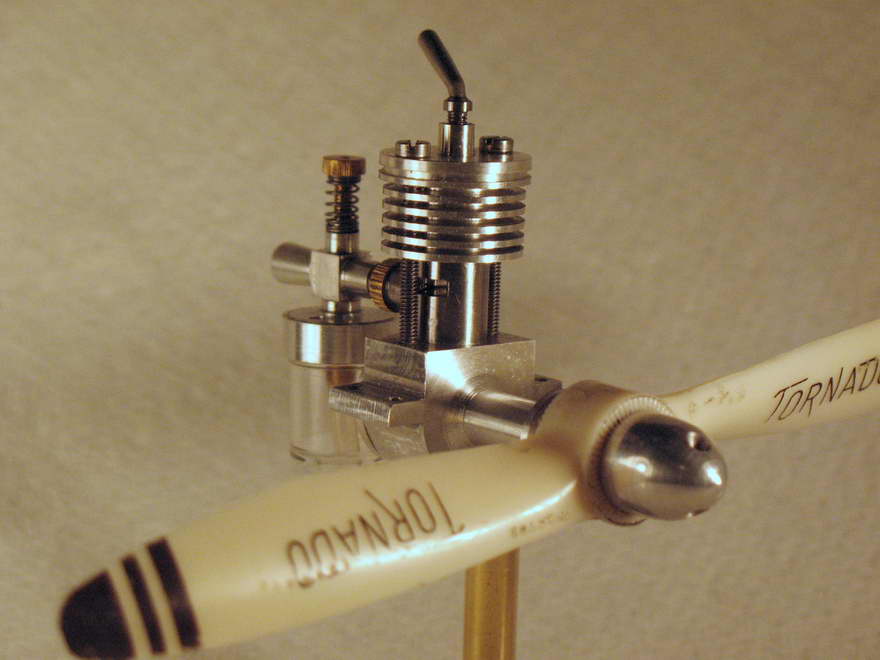
This delightfully made, posed, and photographed little Topsy .375cc diesel is the work of Adam Mills (Surrey, UK). The plans and construction details appeared in the Aeromodeller way back in 1969, but you can still get a copy through their amazingly unnattractively named My Hobby Store service. | |||||||||||||||||||
|
I'm sure many readers will recognize this engine from articles that have appeared in SIC and Model Engine Builder magazines: it is of course, Albert Hutton's magnificent Olympus high performance, in-line four, racing engine. Albert passed away in 2006, but his daughter, Elaine Hutton, kindly placed the engine in the care of MEN Member, Dave Sage, who maintains it and takes it around his native Canada and the USA to the major model engineering shows so all my see and hear Albert's legacy. Dave has provided a stack of photos of this engine for us to enjoy and feel inadequate over; click the thumbnail to go to the Albert Hutton Tribute page. | |||||||||||||||||||

|
This cute and rather Victorian looking engine was designed and developed by Nic Rowlands. Nick offers castings and kits through his R-M-C operation (see the Links Page). There is also a video of it running on u-tube and you'll find the link to that on Nick's web site. The presentation of this engine is superb and the video shows a Mad Scientist type glass tube with a mysterious spark arcing around in time to the engine speed. Things like this, and the engine itself, serve no practical purpose except to please and enthral to observer (and you can bet that the builder gets a kick out of it too). I love it! |