Building the ML Midge
More info on the ML Midge is available here.
 |
 |
 |
The idea for this page came out of correspondence with a fellow engine builder who wanted to progress beyond very simple designs based on the use of some commercial components to one where he could proudly claim to have made everything but the fasteners. Being of European origin, the original Midge plans are metric. As many of the engine builders who contact me are located in the USA, metric is a foreign language to most of them. So I redrew the Midge using Imperial measurements and some minor changes that I hoped would simplify construction. As we exchanged emails discussing what was important and what was not when carving out the crankcase from a solid lump of aluminium, it occurred to me that what has become obvious to me over time, was not so long ago an intimidating mystery. Hence I decided to build another midge case and take photos this time with words that show what is important, and why.
In any single cylinder IC engine that follows a "conventional" design, there are a few things you must get right when machining the crankcase to ensure the engine will run. Apart from obtaining good fits for the crankshaft journal and cylinder liner bore, two other factors require precise work. One is that the the bore for the cylinder be at a precise right angle to the crankshaft axis. Obtaining this is not difficult. The other is that the "deck height" is set as precisely correct as possible. This is the height from the axis of the crankshaft bore to the surface that forms the cylinder liner seat. The procedure given below will show how to achieve both of these. You will need a faceplate for your lathe and an accurate angle plate, along with the usual 3-jaw self-centering chuck. As the crankcase for the Midge is made from "the solid", a 4-jaw independent chuck is also needed. Anything else I've used here is just for my own convenience.
The Midge case will be turned from a small "L" shaped lump of aluminium alloy. "What alloy?" is generally the first question. I like 2024 or 6061 heat treated to T6 condition. This machines beautifully, takes small threads (taps) easily and is quite strong. That's my recommendation. So what am I using here? I've no idea! Just a lump of some alloy lurking under the bench. If you have a piece of 18mm plate lying around, you are half way there. I didn't, so first step for me was to saw off a slice as seen here, using an Asian power band saw. Not a precision machine, but very good at what it does.
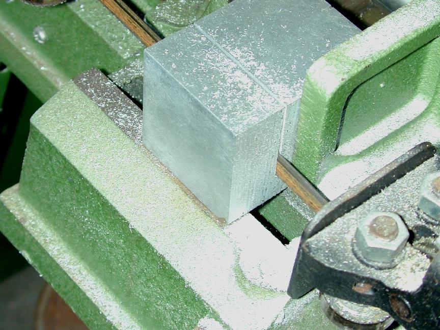
The slightly oversize slice is next finished on either side to a uniform thickness of 18mm, or there abouts. (Aside: If you are not a metric person (I'm not), commit the number 25.4 to memory. To convert millimetres to inches, divide; to go the other way, multiply. If you forget which is which, use either—the result will look wrong if you pick the wrong operation.) It will help subsequent operations if the edges are also finish machined and made close to right angles to each other. A degree or so out won't matter though as we will only be retaining the edge that falls on the bottom of the case. Here I'm using a small shaper which is ex- a WW II era US warship. The shop calculator says 18mm is 0.709". This will be the width of the case, so anywhere plus or minus 0.005" will be fine. If you don't have a shaper (not many people do), it can be milled. If you don't have a vertical miller, it can be fly-cut in the lathe—there's always a way.
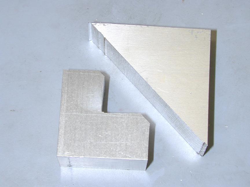
Now we can rough cut the slice to the basic "L" shape. Looking at the piece I'd made, I could sense there were two cases in it, but as hacksaws and bandsaws don't turn corners easily, I could not at first see how to make the cut for one that would not destroy the other. The solution was simple: cut on the diagonal, then convert that to the "L" shape. Always be generous on the oversize side; say 1/32" or more. You can always machine it off, but never put it on! And as we're doing this for enjoyment, production time is not important, right?
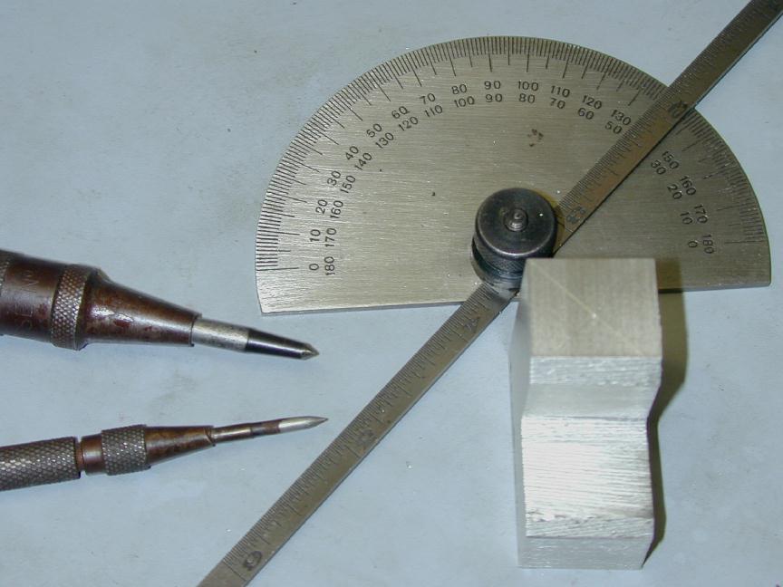
The first operation will be to shape the crankshaft journal and the front face of the cylinder extension. To do this we need to mark the shaft journal center accurately, say within 0.002". Let's make the bottom of the case (mentioned earlier) the datum. By scribing 45 degree diagonals from the two lower corners we can locate the center with acceptable accuracy. The diagonals are scribed using the scriber and protractor, then center-poped lightly as seen in this photograph.
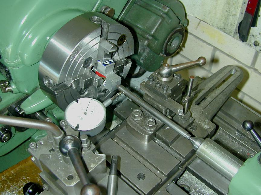
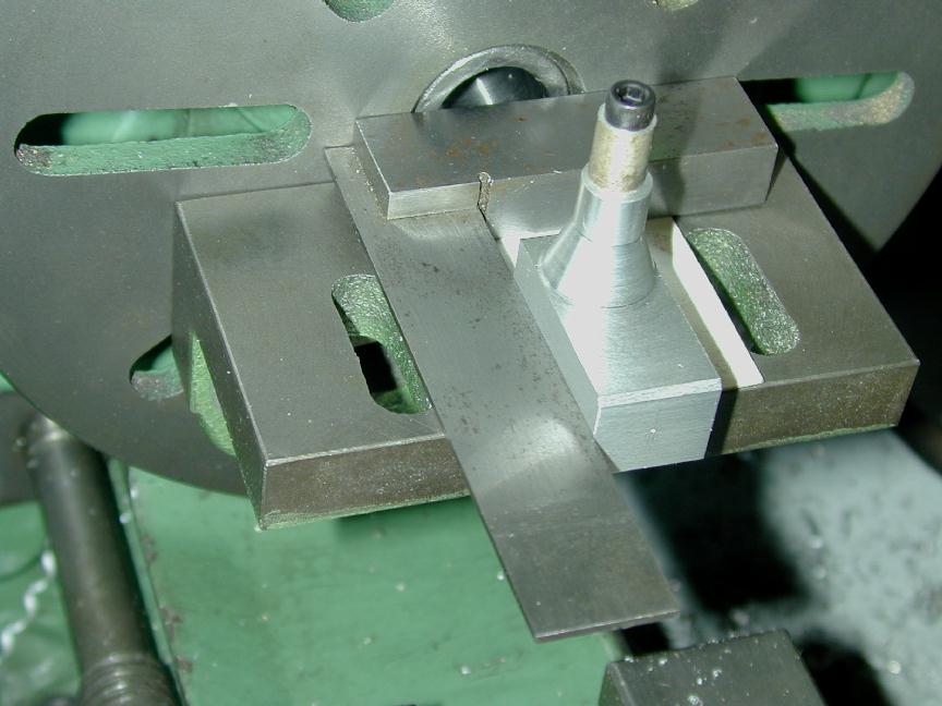
The block is now set up for machining in the 4-jaw independent chuck. Note that one jaw has been reversed to take the thrust loads of cutting and that thin shims (I confess: beer can) are used to protect the block from jaw marks. I generally bring up a dead center in the tail stock to the center-pop mark to get the rough position first, then use a "wobbler" as seen here to get the center running dead true. This was one of the first tools I made (to a George Thomas design). It's a bar of drill rod with a 60 degree point on one end and a spring loaded center on the other. A plunger type Dial Test Indicator (DTI) is set precisely at lathe center height, then placed as close to the point as possible. This "magnifies" the error seen as the work is rotated by hand. With careful tightening of the jaws, the work can be centered so next to no wobble is seen. Be sure the work is positioned so the cut can be taken back to the front of the case. In this shot, my work is too far back. So even though it was centered, it had to be upset, packed and re-centered (*sigh*).
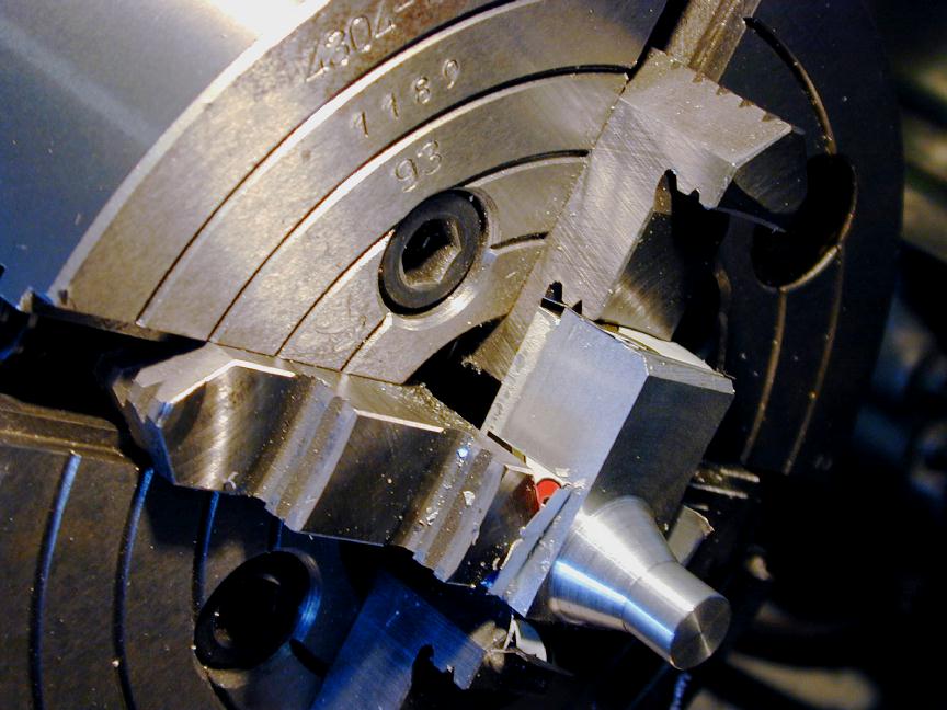
Here's the block after all operations are complete for this step. The important dimension here is the distance from the machined front face of the case to the end of the crankshaft journal projection. An error can be compensated for by adjusting the overall length of the crankshaft, but better not to have to. The outside diameter (OD) is not critical; say within 0.005", but again, a part (the prop driver) will have to be adjusted if you err. Note that the shaft bore is not drilled at this step.
Next, the case cavity and main journal are bored and reamed respectively and the rear face turned at the same setting. Important: The rear face of the case must be at exactly 90 degrees to the crankshaft axis as we will use this face to align the cylinder bore. Drilling, reaming and facing at the same set-up will ensure this. The case is gripped by the turned journal, either in the 3-jaw self-centering chuck with shim to protect the finish, or in a collet as seen here. A little loss of concentricity between the ID and OD does not matter—it's just cosmetic so even a couple of thou won't be noticeable. First the case is center drilled with a #2 center drill and drilled thru under size by at least 1/64". The journal will be reamed using a 7/32" hand reamer and reamers like to cut—if the hole is too close to size the reamer won't have enough to cut to give you a nice smooth, round hole. About 0.016" is a good figure for removal, so drilling #8 followed by 13/32" is a good choice.
The rear of the case can now be faced back to give the correct size. Hitting right on the number is good, but here you can again be up to plus 0.005" (but minus 0.000") with no particular problems. Now the case cavity is drilled and bored to diameter and depth. The diameter can be plus 0.002" (and the backplate adjusted accordingly), but work as closely to dimension as possible on the depth of the cavity, adding on any amount you left the case oversize as the front face sets the position of the crankpin center relative to the cylinder axis. The crankshaft web thickness could be adjusted, but try to avoid this.
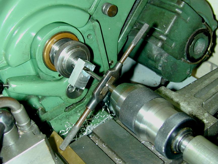
Before reaming, we make a decent chamfer, say 0.025" deep using a countersink. It is deep because some of it will be reamed away, and it's done before reaming (reamering, the Brits would say) because it would raise a burr if done after. Finally for this setup, the main bearing is reamed by "floating" in the reamer while rotating the chuck by hand. If you are tempted to chuck the reamer and run it in under power, you will get an oval hole. The picture here shows the setup I use: the reamer is prevented from rotating by a tap wrench bearing against the cross slide (which is protected by a piece of shim). Hand reamers have provision for "floating" on their heel; large ones have a center drilled into them while smaller ones have a point ground on. In the former case, the reamer is pushed in using a dead center in the tail stock. In the later (as seen here), a female center is gripped in a tailstock mounted chuck to align the point on the heel of the reamer. The chuck is rotated by hand, or slow back gear and the reamer pushed in with the tail stock feed. You need to use lots of "suds" and withdraw frequently to brush away the chips. Important: Always continue rotation while withdrawing the reamer and never, never rotate the chuck backwards unless you want to score the bore.
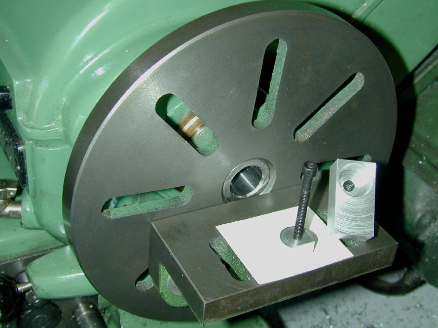
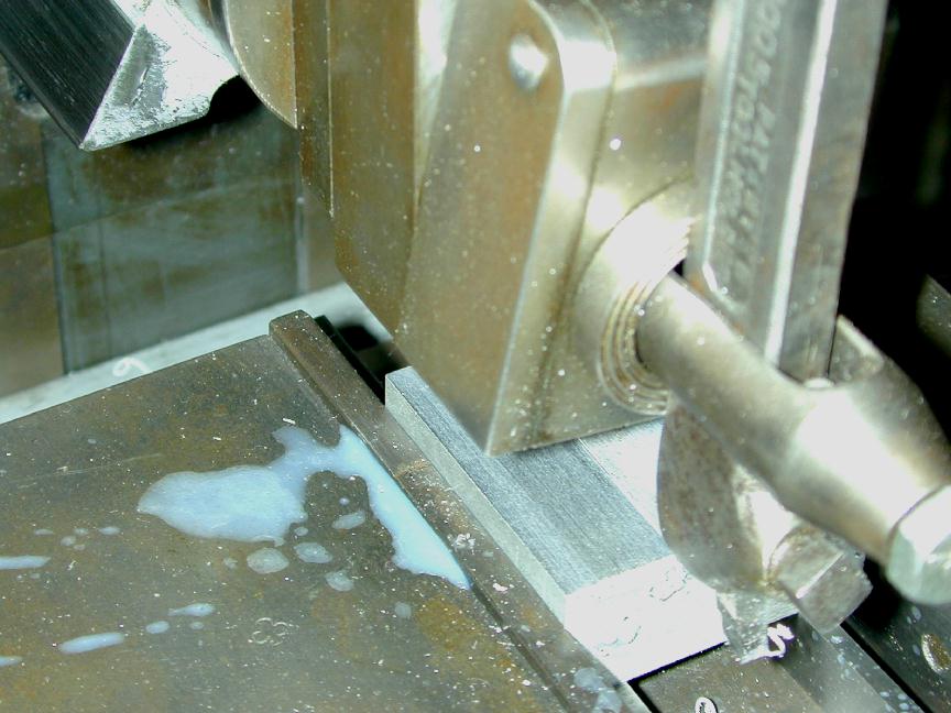
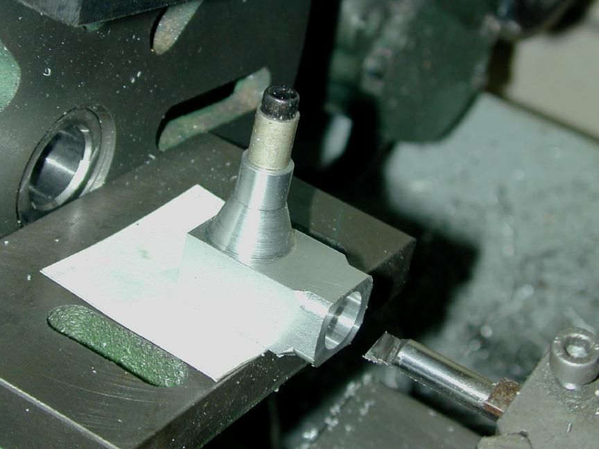
The last machining step is to bore for the cylinder liner. Important: the bore must be at 90 degrees to the crankshaft axis or friction will go through the roof. To achieve this we will clamp the case to an angle plate mounted on a lathe faceplate. Accuracy will be as good as this setup, so we are really in the hands of the angle plate maker. First a plug is machined to be a close sliding fit inside the case cavity. This is drilled thru and tapped 10-32 before being faced off cleanly on the side which will become the base. Next, a flat needs to be milled to such a depth that it will be lower than the lower edge of where the cylinder bore breaks into the crankcase cavity. The plug is then screwed to the angle plate, aligning the flat parallel to the edge of the plate. A piece of note paper (or a business card) is placed under the plug to protect the rear of the case and provide a better no-slip surface. Before mounting the case, accurately measure and record the diameter of your plug, and the width at the flat. This picture shows the mounted plug, angle plate and face plate. (The finish on the back of my case is better than it looks here-honest! I'm blaming the flash and the angle...)
 Locate and center-pop the center of the case top by scribing diagonals, then secure the case to the plate and true it up with a square against the face plate and center using a "wobbler" as before. Center drill, then drill thru using a 1/4" drill until it just breaks through taking care not to drill into the flat on your mounting plug. You can now use the depthing feature of your Vernier callipers to measure from the top of the case to the flat of the plug and begin facing back the top of the cylinder to get the correct deck height. Important: the "deck height" sets the timing of the engine as it locates the ports in the liner relative to the axis of rotation of the crankshaft. It must be as accurate as possible and the ability to measure from the top to a precisely known datum formed by the flat makes this easy. From your recorded measurements, the magic distance is the width, flat to opposite edge, minus the radius (measured diameter divided by 2). Because the plug is a close sliding fit in the case, we can now face away the case top until the measured distance from top to flat is the deck height minus the calculated dimension.
After the deck height is set, the bore can be widened out to within say 1/32" of finished size by drilling. The final dimension is achieved by boring. Important: the cylinder needs to be a tight sliding fit in this bore as we will rely on the fit to prevent gas leakage between exhaust, inlet and transfer ports. How close is "tight"? Some aim for a light press fit, but this makes disassembly a real pain and trial fitting near impossible. You have probably not made the cylinder yet, so bore to the plan dimension as close as possible and make the cylinder to slide firmly into the case; it should be removable with fingers alone, but not be easily rotatable. As you approach within say 0.005" of finished size, run the boring tool in a couple of times without changing the cross slide setting. You'll be amazed how the tool continues to cut, showing just how much spring-back you have been experiencing with the tool. I've seen as much as another 0.002" of bore added with no change in depth of cut. The final pass should repeat this process.
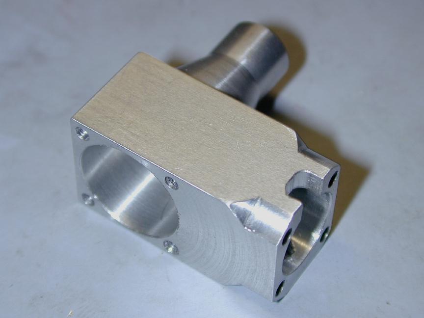
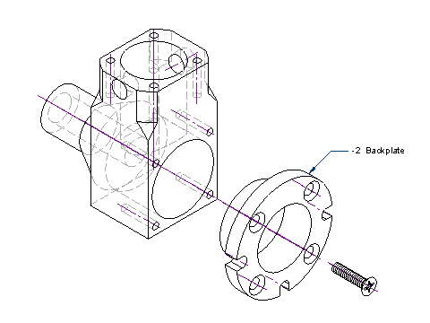
All that remains is to cut the exhaust opening, drill and tap for the venturi and all the 8BA (or 2-56) blind mounting holes. The photo here shows the finished case. The inlet is positioned relative to the top of the case, but is not overly critical (within say 0.005") as there will be a small cavity between the end of the screwed in venturi and the inlet hole in the liner that will compensate. When drilling the backplate mounting holes, be careful that the top two don't break through into the cylinder bore. Any screw hole that breaks into the case cavity is a potential point where pressure can be lost—not a disaster, but a situation to be avoided!
Just a final caution about burrs: all openings should be lightly chamfered to accommodate the radius of the mating parts (ie, the backplate and cylinder liner flange). Angling the boring tool to 45 degrees and plunging it in along the lathe axis will work, but I find this raises a larger burr than actually taking the time to set over the compound slide to 45 degrees and making the cut that way. The other place where a burr can impact gas seals is on the backplate. All taps will raise a burr around the lip of the hole. Trying to de-burr after (usually by rotating a large twist drill in the tapped hole) will raise a smaller, large diameter burr and mutilate the thread in the opening. The "pro" way is to spot the hole lightly with a clearance size drill before tapping: just enough to have the full diameter cut the surface. Now when the tap raises a burr, it will be below the surface we want to remain flat. Looks good too—you should be able to see it in the previous photo.
 |
 |
 |
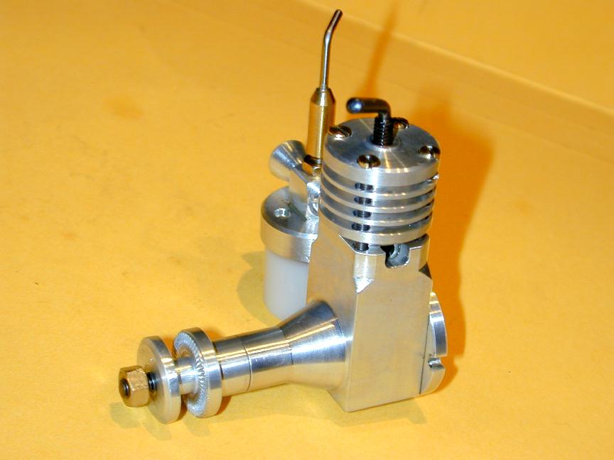
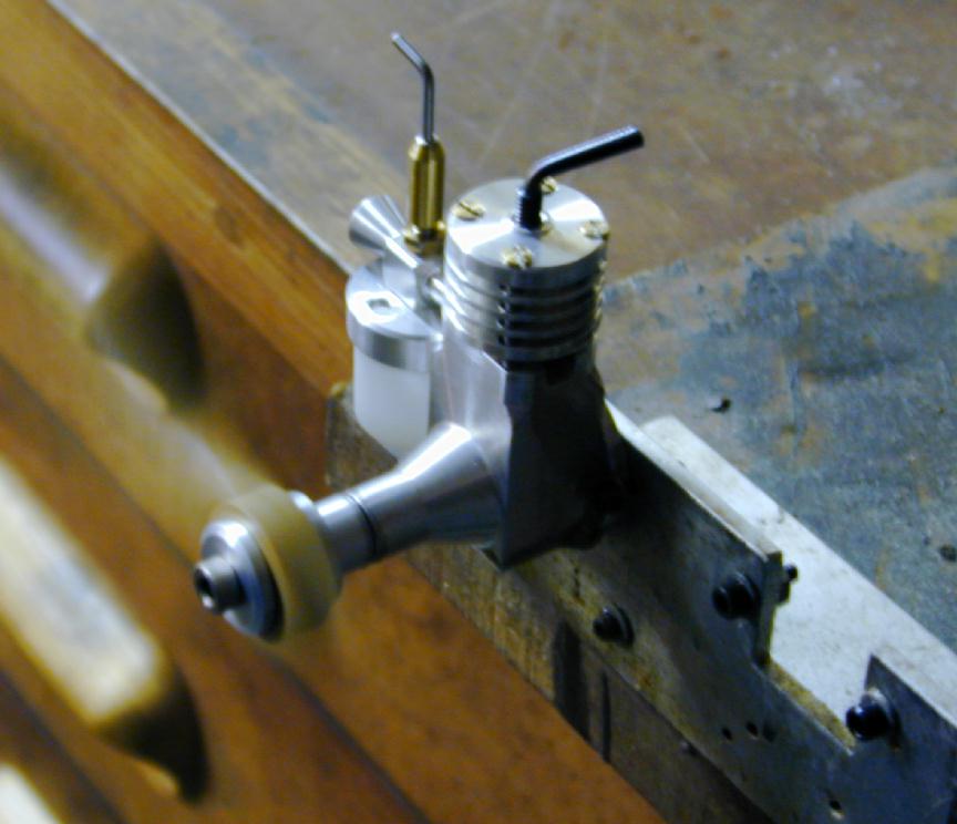
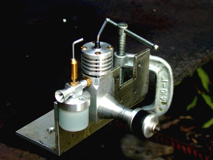
They say that the proof of the pudding is in the making—We say the proof of the engine is in pulling the skin off the said pudding... The ML Midge is a good second project choice for amateur machinists, or a good first choice for anyone new to IC engines, but not to machining. In this photo, the Midge is swinging a 8x4 wood prop quite happily—not bad for an 049! After several tankfuls to break it in, the Midge turns a 6x4 nylon at about 8K rpm (the photo showing 7.5K was before it had freed up completely). It responds well to changes in comp and needle, but is sensitive to neither and can be backed off to a very low RPM making it an ideal little free flight sport diesel.
This article has skipped over making things like crankshafts, cylinders, pistons etc as these are well covered on other pages on this site. I hope stepping you through the stages in making a crankcase form the solid has shown that it is not difficult at all. In fact, the steps are equally applicable to machining a casting. You simply need to get the bore axis at right angles to the shaft, good fits on the shaft and liner, plus get the deck height right. Small errors can sometimes be compensated for by adjusting the size of other parts, but it's easier not to have to, right? The Midge is a straight forward design that can be made from the average scrap bin and tug around a small free-flight cabin model, or a "schoolyard R/C" job with ease. Mine is very easy starting, docile, amazingly quite (given that the exhaust is a single 3mm hole, this should not be surprising). The design should also lend itself to experiments. So a hearty "well done" goes to designer, Mark Lubbock.
![]()
 Home
Home
This page designed to look best when using anything but IE!
Please submit all questions and comments to [email protected]