Cam Making Made Easy
by Graham Meek (UK)
Ron Chernich, March 2009
The first four-stroke engine I made was to an American design based on a single cylinder "Hit and Miss" horizontal engine. Three things about this design appealed to me; one was the fact that the entire engine was made from "Odds and Ends" which is how the engine got its name. The second was a technique on how to make the gear cutters necessary, which I have passed on in previous EIM articles. Lastly, there was only one "Tangential" cam to make which was a simple rotary table job, the intake valve working on suction alone. Whilst it was originally designed and built to run on petrol, it has been successfully running "compression ignition" style on paraffin/kerosene—with a slight modification of course. My second engine, a side-valve, came about after a career change and the need to learn AutoCAD. I could think of no better way than to design and build an engine in order to keep my interest in the learning curve. Again I wanted to see if a side-valve engine could be persuaded to run compression ignition style. The answer is yes, but it lacked the docile nature of a petrol side-valve, and it will subsequently be converted to spark ignition. It was whilst designing this engine that I hit upon the following method of producing the Cams.
Most of the designs of Edgar T Westbury and L C Mason use cams which have a radial flank. Whilst ETW's method of camshaft manufacture is and was ingenious at the time, it does not lend itself to making the cams with hardened surfaces easily. If the entire camshaft is made from "Silver Steel" and hardened then distortion might present bearing alignment problems, especially on multi-cylinder engines. Many builders have gone down this route but have resorted to building specialist-grinding machines to rectify this distortion. ETW also states in his construction article on the "Seal" that by far the quickest way to manufacture a camshaft was to make all the inlet and all the exhaust cams together. The reasons he did not adopt this method was he felt the angular relationship cam to cam would be difficult to maintain and the means of holding each cam in position. I had decided that the cams for the Side-valve engine would be hardened; it was therefore decided to adopt LCM's built up camshaft approach which he used in the "Mastiff" engine. Although my design had only two cams I was not altogether happy with the nibbling aspect of forming the cam and subsequent hand finishing by filing. Further I was not happy with aligning the cams "by eye" in a jig—although that is not saying that this method is not satisfactory. For my peace of mind, I wanted a more positive, engineered location method which cut out relying on my eyesight.
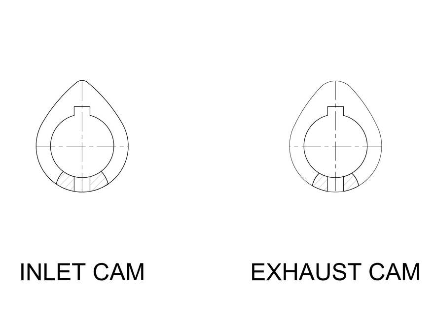
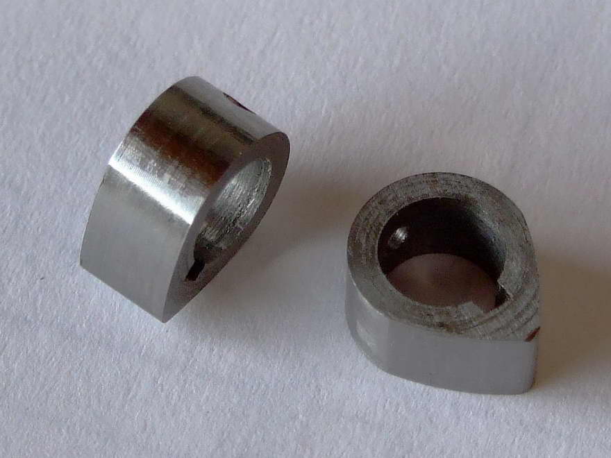
Taking the centre line that passes through the "nose radius" of the cam, each flank radius is symmetrically disposed about this centre line. It is along this centre line of the cam under the "nose" where most of the material is. Therefore if a "keyway" were to be put in at this location, then it would act, as an indexing point and it would not weaken the cam in any way. This keyway and the bore now become an effective means of holding and locating the cam in the subsequent machining operations necessary to finish the profile. It also becomes a means of locating the cam on the shaft in relation to the other cams and there-by solves one of ETW's problems.
On most of the four-stroke engine designs that I have come across, the flank radii are the same on both the inlet and exhaust cams, the only difference being their respective opening durations. This is determined by the angle between the flanks (times two for crankshaft degrees), and the nose radius on the exhaust cam which needs to larger due to the exhaust being generally open longer. It is soon realised that both cams can be machined on the same jig provided the centres are accurately located. Having worked out a reliable method of producing the flanks, it was now time to consider the removal of the material that forms the "back" of the cam around the "base circle" without resorting to nibbling and filing. If a fixture on a rotary table with an indexing pin to locate the keyway was so arranged, then the removal of the remaining material could quite easily be accomplished with the side of an end mill. Further, if the fixture was "set-up" on the rotary table such that it had a guide and a means of accurately locating it "endwise", then the nose radius could be put on using the same fixture with the minimum of setting up. The method of locating the cam in my side valve engine was by a fitted key for radial location and spacers as used by LCM for endwise location, the whole assembly held together with "Loctite". This can be and has been further refined to just using short pins instead of the fitted key, but still relying on the spacers for endwise location. A further adaptation or evolution is that which I am about to use on the construction of the Seagull engine designed by ETW.
I had decided to build this engine as a "Project" to help me convalesce after an operation. During my initial immobility, a good friend loaned me some books on "Lister Diesel" engines. Whilst reading through, I happened to notice that the camshaft was basically a plain shaft with the cams pinned in place by taper pins. It is at moments like these that the "little grey cells" go into warp drive. I quickly realised if I drilled a hole in the cam opposite to and of the same size as the keyway, then these cams could be located both radially and endwise in one foul swoop. There were advantages to this method; the pin would be in a non-working area of the cam and should there be a desire to try different valve event timing, then cams could be salvaged from the old camshaft. It will be seen from the drawings that accompany this article that further refinements can be added to the milling fixture that remove any guess work as regards intersection points. Reamed holes can be put in at known radii along the lines of intersection and these can be used along with the table stops of George Thomas's small rotary table to precisely locate the intersection point. This was the method adopted for the manufacture of Dr J Beddard's much-modified "Chenery V-Twin". It can be taken further to include the undercutting of the base circle for the tappet allowance. Similarly, if the flanks are left oversize by a small amount then when the cams have been hardened and tempered, these can then be finished to size using a toolpost grinder by simply remounting on the flank fixture.
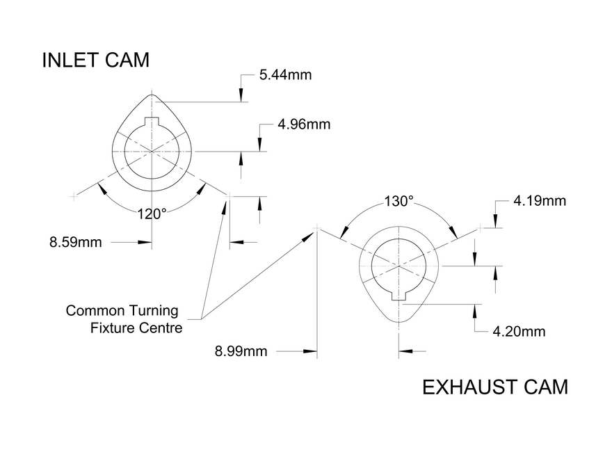
The drawings included are for the "Seagull" cams and a few words about these may help to make things a little clearer as regards establishing where the flank radii originate from. If we take the inlet cam there is an angle shown of 120 these are the points where the tappet starts and stops moving. It is also the point where the flank radius starts; if these lines are extended, then along this line is the centre point for the flank radius. Using the power of AutoCAD it is literally a few minutes work to draw these cams out, and it is interesting to note that using this method a small inaccuracy has been found between my cams and ETW's. I am going to assume that I am in the wrong and that I have missed something, but if I should tell you that my worst error is 0.13mm (0.005") on maximum lift and my best error is 0.01mm (0.0004"), then I think it just goes to show how good a designer ETW was, given that he was probably using paper, pencil, slide rule and logarithms. Since writing this article I have read that there was a good deal of involvement on ETW's Projects by Prof. Dennis Chaddock, so perhaps he should take the credit, either way we owe a lot to the both of them.
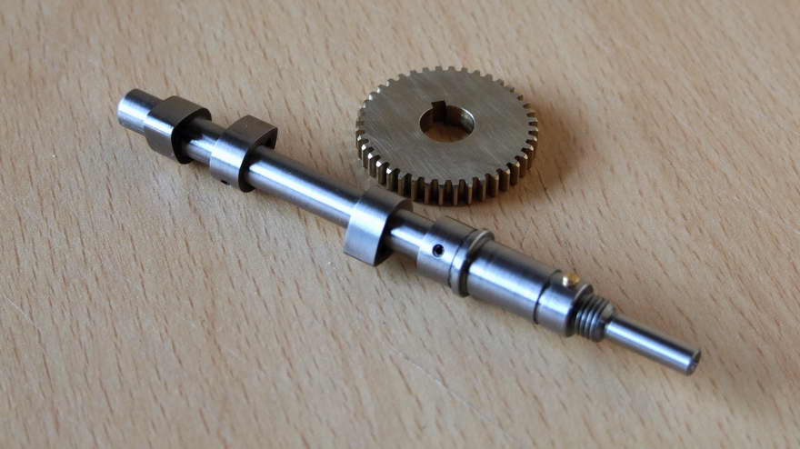
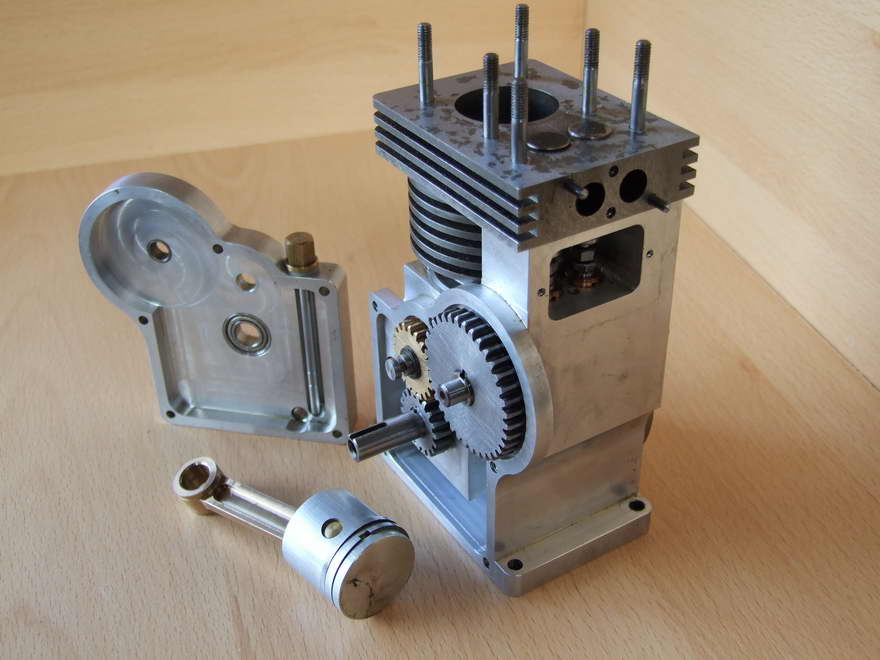
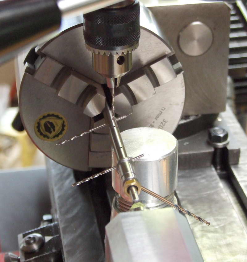
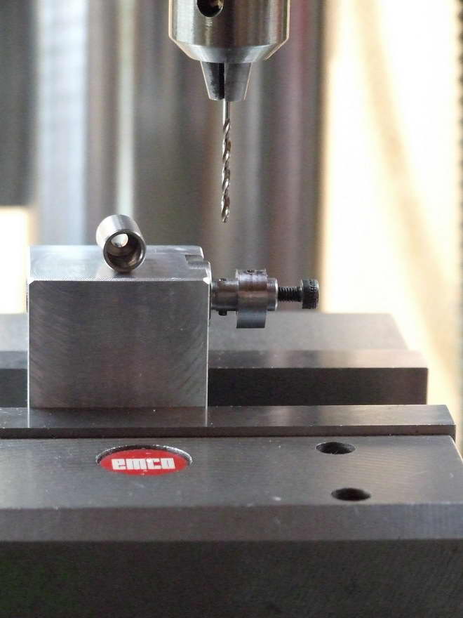
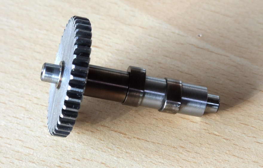
If time is taken to look at most of ETW's engine drawings, then very often he shows the relative positions of each cam on the shaft. To illustrate this I have included a photograph of the finished Seagull camshaft. If attention is paid to the centrelines alone, then it is soon realised that both inlet and exhaust cams share a common centreline. It is only the relative position of the "Cam nose" that dictates the position on the shaft. In the case of Seagull, the cams are just a mirror image of each other. This symmetry will also be noticed in other multi-cylinder engines. When making the embryo camshaft for Seagull as shown in the photograph, there are only two angular moves to make either side of the "Timing Gear" key location (large drill on the right pointing downwards). The only other requirement is to ensure the linear positions of the cams along the shaft, which in this case is a standard piece of 6mm "Silver Steel".
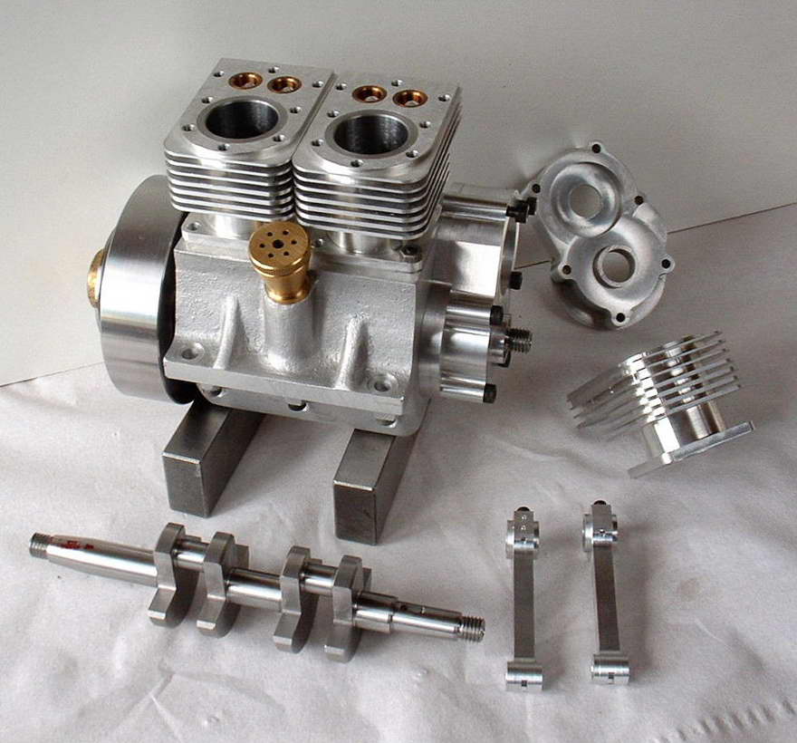
 All my engines to date use timing gears that are keyed in position and this is worked out at the design stage. In the case of Seagull because of the additional idler timing gear location it is necessary that the crankshaft pinion be produced with a 4-degree offset of the gear relative to the keyway at top dead centre. When on final assembly the valve timing was checked all valves opened and closed in the correct places. I enclose a photograph of my "Project"; it has been built to be air-cooled, hopefully by an engine driven fan. I feel sure though that the smaller modular fans used in computers could be used via a thermistor to thermostatically control cooling. (One point in passing for those who like me prefer traditional points ignition, "Tungsten Points" with a 10BA thread on are to be found in radio "Morse Keys" a few being supplied by a "Steam Radio" friend.)
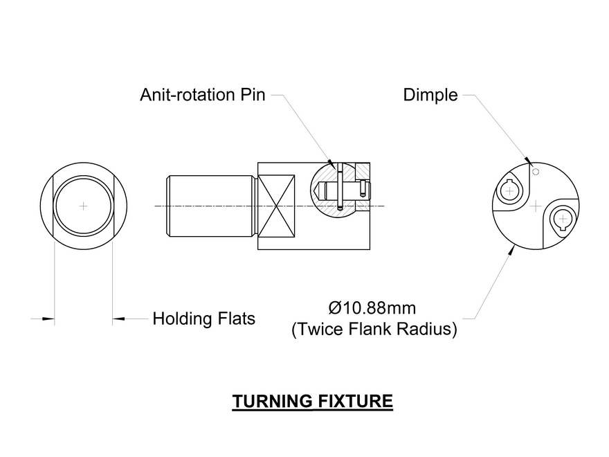
Although I have included General Arrangement drawing of the turning fixture a few words about the construction may be of help. The Flank Fixture is a piece of mild steel the two flats on the outside diameter are to allow it to be gripped in the machine vice to machine the pockets for the embryo cams. The flats also allow the fixture to be reset without loss of radial orientation, accurately locating the key and anti rotation pins, again in the machine vice. From the photograph you will see a groove machined until it almost touches the locating pin, this is to allow a lever to assist the removal of the cam, once the flank has been turned. You will also note there is a "dimple" drilled adjacent the inlet cam, this is vital to save confusion should you decide to grind your cams.
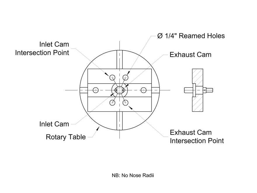
The Milling Fixture consists of an aluminium base with a mild steel spigot pressed in, on the fixture centreline, what is not evident from the photograph is that the spigot has a head with two flats on that locates in a slot in the underside of the base. This ensures there are no mishaps during the milling operations due to the spigot turning; again it allows the radial orientation to be maintained when the location key is put in. It also means at a later date the base can be utilised for another cam or another purpose.
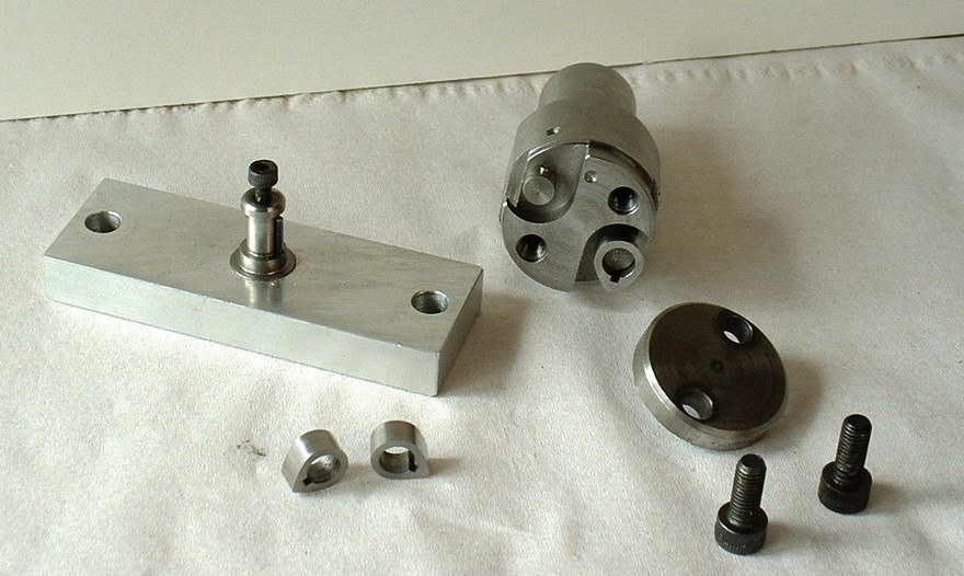 The base is machined to known convenient dimensions; this makes setting up on the rotary table much easier. Because I wanted to do two cams at once it will be noticed that this fixture has a vertical location peg, which necessitated the location diameter being machined away slightly to clear the pin. By far the easier option is a short location peg at two locations radially.
 |
 |
 |
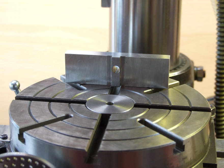
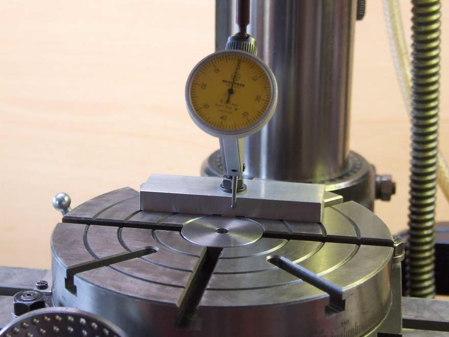
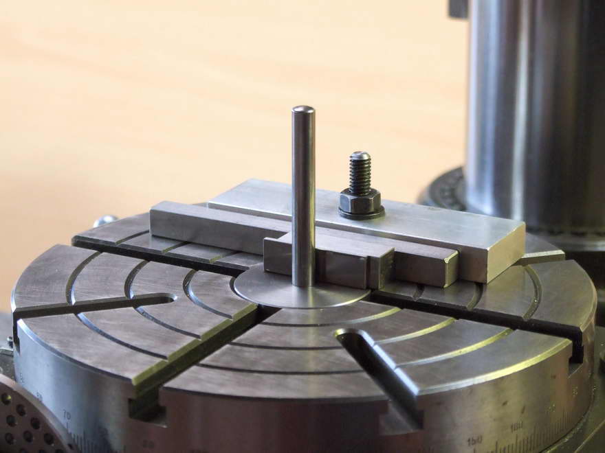
I have included several photographs of the set-up procedure; the first photograph shows my Rotary Table Fence. This is machined on one edge and a Tenon is machined in the base square to the edge and a sliding fit in the rotary table Tee Slot. With the rotary table set at Zero degrees this fence is "clocked" to ensure the edge is parallel to the milling machine table movement. The next photograph shows the machine spindle centreline being aligned with the rotary table centreline.
 |
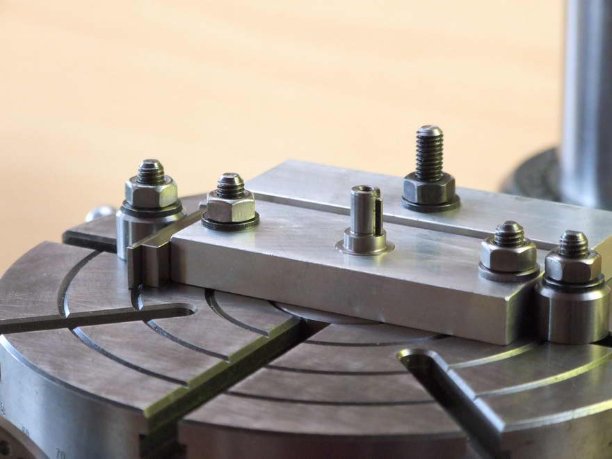 |
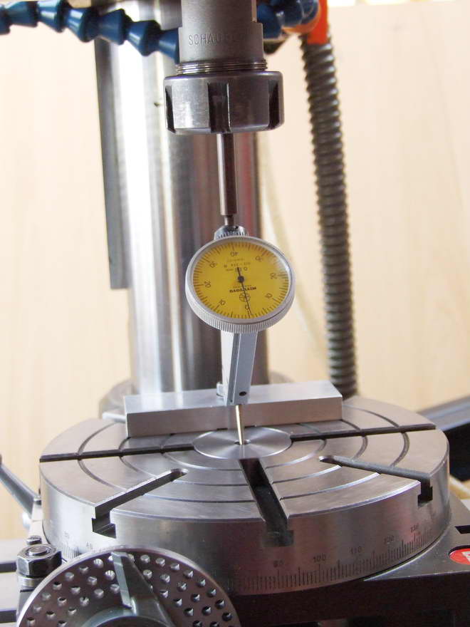
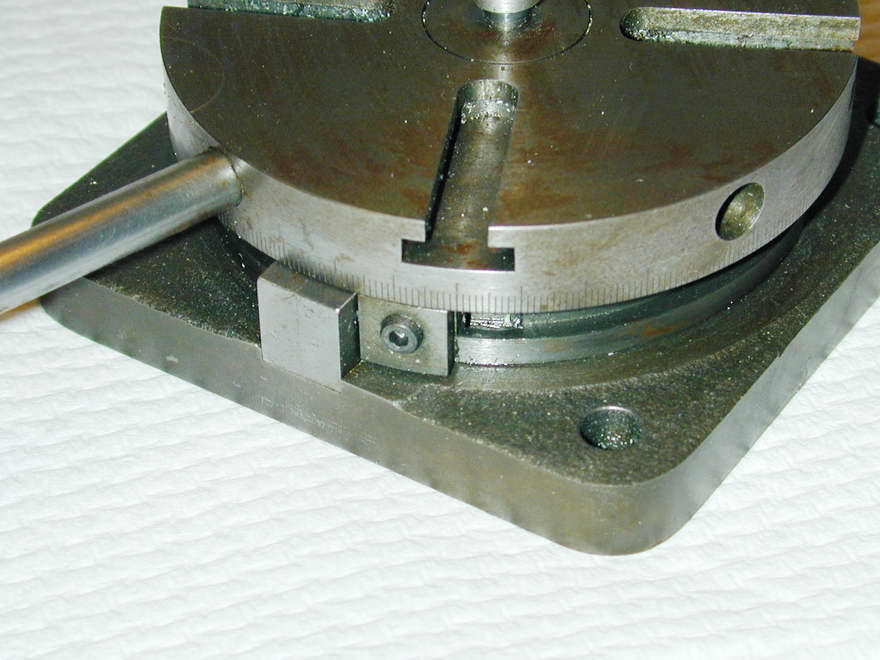
To minimise the set-up time the fence is now set using "slip gauges", (half the width of the fixture minus half the diameter of the pin), a centre pin and a necessary parallel. Mounting the fixture on the rotary table and up against the parallel it is only necessary to "clock" the locating pin of the fixture in one plane. Once set, a stop is set on the right-hand end, a further stop is set at the left-hand end using slip gauges. This dimension is the centre distance of the nose radius; it will vary from exhaust to inlet cam.
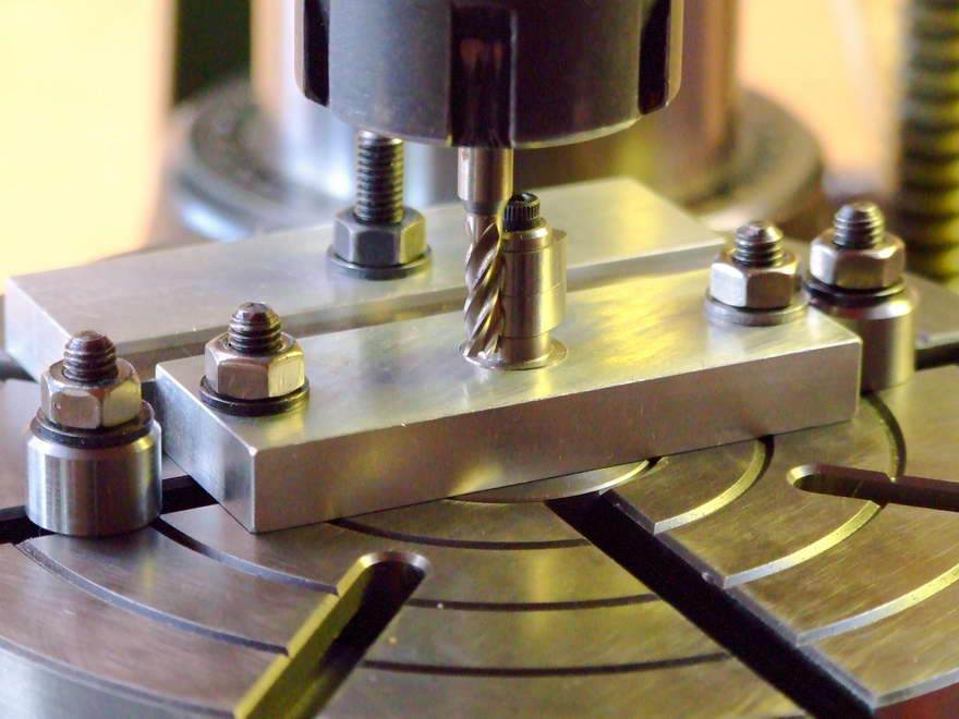
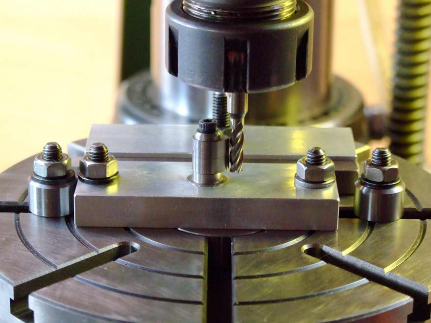
You can save a considerable amount of time on a multi-cylindered engine by doing two cams at once as in the photograph. If you employ some "time and motion" to the procedure it will be found quicker to do the nose radii first, move the fixture to do the base circle, then change the blanks and do the base circle on the next cam, finally reset to do the next nose radius.
 A photograph shows the finished cams after milling all that remains to be done is drill the roll-pin hole in the back of the cam a further drilling jig is shown. From this photograph it will be easy to see the locating key on the under side of the locating pin, the cam sits up against the shoulder and is held in place by the tube spacer shown on top of the jig. A small flat about 2mm wide is machined on the top of the locating pin along its length, to clear the burr produced from the drilling operation and therefore make getting the cam off easier.
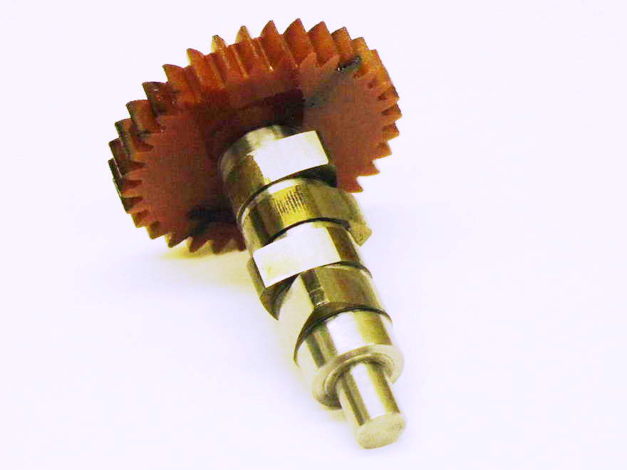
I have included photographs of the very first camshaft for the Side Valve engine and also the camshaft for the much Modified Chenery V-Twin that incidentally has a Tufnol timing gear. (Again Dr J Beddard following the same technique as used for the Handwheel Dial ref. EIM March 2007 onwards, made the cutters for his gears). Along with the Seagull camshaft we have the evolutionary lineage of the technique described here.
Recently I was called upon to help out, word gets around that there is somebody in our Avenue who can fix things. The fix came in the form of a Briggs & Stratton vertical crankshaft lawn mower engine, the shaft being anything but straight. I have salvaged several of these in the past but this time when I took it apart I had quite a surprise. Not only was the main cylinder bore without a liner but also the camshaft was a plastic injection moulded affair, which had an integral timing gear and a central ground steel shaft. Obviously plastic cams with plenty of splash lubrication are adequate to do the job. I intend to try the Seagull out with cams made out of Delrin; they say there is nothing new under the sun and how right this statement is.
The method of Camshaft production I have put forward I feel has simplified manufacture considerably, it does not involve making a complex jig to manufacture or assemble, and it uses far less material in manufacture. Something which has to be taken into consideration these days given the high cost of the raw materials, and the energy costs necessary in converting that material into our works of art, be it petrol engines, steam locomotives, traction engines or what ever.
![]()

This page designed to look best when using anything but IE!
Please submit all questions and comments to
[email protected]