Editorial
This is being written rather late in the month—the last day to be precise. In keeping to my self-imposed deadline (yes, lunacy helps) I was starting to panic over what I was going to fill up a web-page with. Then, all at once things started flooding in to the point that I'm wondering if I've got enough time left to collate and prepare it all! There has been a little action in my shop, nothing that will make riviting reading, but I believe the other stuff will make up for that.
For no readily apparent reason, I've also changed the page layout slightly to start off with a Table of Contents that breaks the content down into items which tend to appear each month on a more or less consistent basis, and the other stuff. As a disgustingly self-righteous purist, I write all this in raw HTML using vi on a Unix box. Microsoft? Just say no.
Looks like I'm finding the AHC jag hard to kick. Having finished another two in August, and finding I still have three machined cases left to fill, I'm making one last (!?) side-port for a cpl Smith who absolutely must have serial #10—which is actually engine #11, since like a good software engineer, I started numbering from zero. At the same time, I've decided to make a pair of rear-rotary-valve "Red Rover" variants. I want to try out an idea I have for this set-up that will be slightly different from the original design by Bert Striegler, and also from Roger Schroeder's adaptation of Bert's concept. Mine will be along the lines of the Mills 2.4cc RRV. If it's not a great success, a simple backplate change will convert it to either of the other two models.
I'm also pleased to report that I've spoken with Ray Strinati following his stroke last month and I'm happy to say he sounds as alert and articulate as ever. He says that if anything, his memory has improved, although he's not getting around as vigorously as before and the medicos have decreed that he fit some hand-rails to his house before being allowed home permanently. His passion for engine collecting is undiminished too, which leads us to another follow-up...
The Miguel de Racougne Collection
In May this year, these pages reported the sad passing of Miguel de Racougne due to inoperable cancer. As Miguel's stated aim in his last years was to go out with the largest model engine collection in the world, the obvious question was what will become of it? Well, late this past month, I received an email from one of aeromodeling living legends and treasures, Ron Moulton. Ron and UK Motor Boy Eric Offen have the enviable (and onerous, and therefore maybe un-enviable) task of breaking Miguel's engines into lots for auction and setting the reserves on the lots. This is no down-market disposal. The auction, comprising some 1200 articles, divided into lots of five or so, will be conducted by Christies of London on January 20, 2004. Ron says he's completely frazzled. Eric has been to stunned to say anything.
Ozzie Motor Boy David Owen reports, seriously for a change, that he is prepared to travel to London to accompany, advise and/or represent a serious buyer. This is a major auction and David can provide invaluable and recognized expert assistance to such a person. Contact David on +61 2 4227 2699, or email him at [email protected].
The Doug McHard Collection
Ron also alerted me to another auction, namely the engine collection of the late Doug McHard. This name should be well known to English and Australian modelers as the man behind the Aeromodeller SE5a free-flight scale design (the free plan in the December 55 Aeromodeller if my memory is correct) and the "Wee Snifter" from Model Aircraft, amongst many, many others. This auction will be on December 6th at Gildings. It will comprise the 140 engines from Doug's collection, and will be supplemented by others to an estimated total of 400 engines! The web page observes the growing world-wide phenomena of model engine collecting—an observation that can be verified by anyone who has watched the crazy prices even junk engines are fetching on eBay. So checkout the link and speak with your bank-manager (while I talk with my insurance agent!)
New Books and Magazines This Month
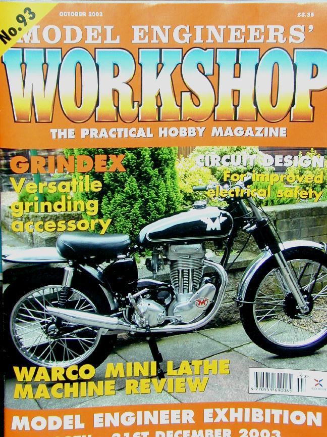
 Another Model Engineers Workshop arrived this month which was a bit of a surprise since they publish on a two-month schedule and I also got one last month. Not much in it for model engine builders, although the trade information page did note that the change of hands at Hemingway is now complete and the operation has been re-vitalized by the new owners. The link address has not changed, but the look and feel of the site has, so it's worth a revisit (even if some damn glitzy web scripting-thinggy caused my pointer to shimmy like your sister Kate until I killed the browser instance). Mention of MEW #93 causes me to recall #92 reported on here last month, which contained an article that provides an ideal segue into..
More Progress on the Brian Perkins Hydra
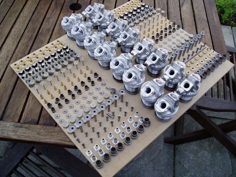
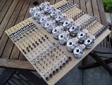 An email arrived last month from Brian with a picture of an Absolutely Fabulous display board he created for the annual Bristol Exhibition. The board mounts a staggering number of the head parts for his Bristol Hydra. Always one to enjoy a mechanical puzzle, I stared at that pic (probably as you've just done) and tried to figure out what each little bit does. Remember, while the Hydra is a radial, it's cylinders are in-line allowing the cams to resemble the OHV arrangement generally found in V and "straight" auto (and aero!) engines. The purpose of some were obvious, like the angle gear drives. Others remained mysteries, so I asked Brian, who replied:
"...the layout was done for the Bristol exhibition recently
and it also allows me to keep track of the bits and pieces.
Starting from the back
- row 1 & 2 cam shaft bearings
- row 3 & 4 front cam shaft bearings
- row 5 & 6 valve inserts (inlet on left, exhaust on right)
- row 7 & 8 valves (inlet on left, exhaust on right)
- row 9 & 10 valve guides
- row 11 & 12 cams (inlet on left, exhaust on right)
- row 13 & 14 valve spring caps
- row 15 & 16 bucket tappets
- row 17 rear cam shaft with 27t. bevel
- row 18 12t transfer bevels
- row 19 (left) 12t drive bevels (right) fitting for cam drive shaft cover
- row 20 & 21(left) telescopic transfer shaft brgs. (right) fitting for cam
drive shaft cover
- row 22 exhaust stubs (nipple, locking ring and stub)
I have subsequently finished the front cam shafts with their universal joints
for connection to the rear cam shafts but I shall have to do some
re-arranging if I want to include them in the display!!!!
"
More parts for Brian's Hydra appear in the Gallery. The finished engine will be outstanding, but I really like these "exploded" shots more as they emphasize the effort that has gone into the engine and make me think about how I'd setup to machine something like that... (as if!)
Engine Of The Month: Feeney Four-Stroke
Over the past few months, I seem to have been adding researched engine features to the Finder at the rate of about one per month, so let's see if I can make it official and present something a little in-depth on an engine every month. This month it's the Feeney Four-Stroke. And as the source of some of the assertions regarding this engine may seem questionable coming from a guy who was not born until five years after the engine disappeared, and on a different continent to boot, this disertation includes the references used in the good, time-honored, academic fashion.
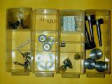
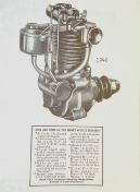 The reason this engine was chosen arose from an email from Art DeKalb. Even though the Feeney appeared only briefly just before WWII, comparatively modern-day Feeney casting sets were produced in the early 1980's by the Precision Service Company, run by Art. His casting sets reproduced the cast aluminum-bronze crankshaft, valves and rockers, the intricately cored aluminum cylinder, and other aluminum parts. The kits were quite complete and included a full set of machine screws, plus the spiral-cut gears required for the cam drive, which would be beyond the capabilities of even well-equipped home-shops. Like Art's other kits, the Feeney includes professionally drafted, full size drawings, running to 45 sheets detailing all components, including tolerances as required.
Limited Run Feeney 10 and 15cc Kits
Although the Feeney casting sets are no longer available from Art, he is still in the casting business, concentrating on vintage outboard engine parts. In his email, Art reported that he is considering making another small run of Feeney kits. The cruncher is the spiral-cut cam drive gears. These are not your standard Boston Gear catalogue item and have to be specially made. To get the price of their manufacture for inclusion with the kits down to an acceptable figure, he will need to take actual, hard cash deposits for eight to ten kits before committing capital to the venture.
Art says that he will produce the 10 and 15cc versions which will sell for US$200, plus shipping and handling. Subscribers must state the size they want at the time of placing the order, which must be accompanied by an up-front deposit of US$75 per kit which is non-refundable unless he is unable to deliver before January first, 2005. So if you are after a full kit for a very rare and historic engine, contact Art for details (and mention that you read about it here) and just think what one of these will fetch when your estate comes up at Christies!
And for the record, I have no financial connection with this venture, apart from needing one gear so I can build the kit I have. In the past, I finished a couple of Stuart steam engines for Art in exchange for Elf casting kits. So help me out here guys, order kits so Art can commission the gear making, and my enemies can no longer assert that Ron has a cog missing!
The Viper
 Modellers who have poured over the pages of Aeromodeller circa late 40's will instantly recognize the name C Rupert Moore as cover artist, model designer and patent holder of the "Moore Drive" and the (ahem..) "Moore Diaphragm" — which is not what you think, but a device to prevent rubber bunching causing CG change induced trim shift in his big, rubber-powered scale models like the 44" Tiger Moth and others. The mail from Ron Moulton caused Ken Croft to forward a photo of Ron, circa 2003. Ron is the gentleman on the left; on the right is Mike Beach, restorer of historic models. In the foreground is the Moore "Viper". Yes, that's right; The Moore Viper, the original, recently restored by Mike. The model, although not a true scale design, is representative of what a between-the-wars RAAF interceptor monoplane may have looked like (the fin is very "Hawker").

Ken took these photos at the Middle Wallop Eurochamps in England earlier this year. Although restoration of the Viper is complete, restoration of a way to wind the thing is not. The Viper uses a geared drive with four skeins of rubber trying to turn themselves into an instant cats-cradle. Packing on a few hand-wound turns, as shown here, produced nothing that could even remotely be dignified as a powered-glide, so an actual flight of the Viper will have to wait until this problem is solved. Incidentally, More's models used a lot of hardwood in their construction and he was fond of binding joints with cotton before cementing (with a cellulose based cement). This has allowed the models to survive the 50+ odd years to today, but they are heavy.
 This pic shows another of Rupert Moore's models as restored by Mike (who holds the model here). It is the "Castor", a faux WWII English bomber design the looks like it could have easily rolled out of the factories of Miles, or Blackburn. As far as I know, plans were never published, although the model featured in a series of articles on rubber powered scale aircraft design in Aeromodeller during the late 40's. It uses the patented "Moore Drive" mentioned earlier where three skeins of rubber are geared together in the fuselage and a system of forked, intermeshing cranks drives the twin contra-rotating props (outward) with very little friction loss. I have pics of this model and its internals (again, courtesy of Ken Croft), but I'll keep them for a Moore Tribute Page, some time in the future. Incidentally, the direction of contra-rotation, outwards or inwards is an important design decision, not an arbitrary one. Why is left as an exercise to the student (hint: start your research with the Lockheed P38 Lightening).
Morton M 14
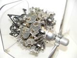 This is just one of the engines that will go before the hammer at Christies as part of Miguel's estate auction. I believe it is one of the variations on the Morton theme made by Dennis Fadden of Vancouver BC using Satra castings (and a LOT of ingenuity). A rear cover of SIC featured Dennis' Mortons showing a single, a three cylinder radial, a cut-away "standard" M5 radial, and a dual bank 14, if not this dual bank 14—although the prop hub shown here is different. Just bending and assembling the inlet pipes alone is an achievement worthy of acclamation, let alone the rest! If anyone knows how to get in touch with Dennis (or knows for certain just who made the engine), we'd appreciate the information. Knowing the provenance of the engine will certainly enhance it's value at the auction.
Tech Tip of the Month: Crankcase Machining
Each month I receive nice compliments from readers, often followed by a technical question. The time required to generate the required response goes un-noticed in the warm glow of the afore-mentioned compliments, so everybody wins—I think!

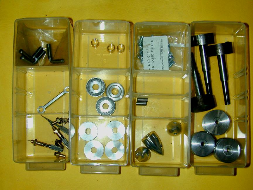
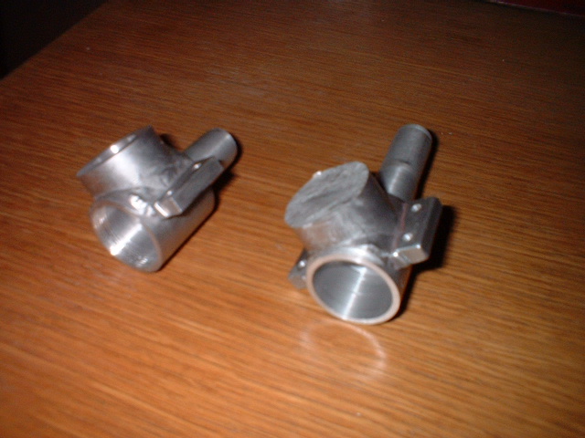
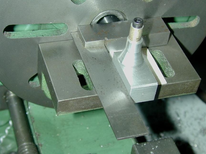
This past month, a builder in Norway sent the picture here of a case for a 2.5cc design he had cast—from a Peugeot cylinder head, no less—and machined, noting that he believed the crankshaft axis and cylinder bore were not perfectly at right angles. He was concerned, and was wondering just how concerned he should be. That, as they say, is a very good question.
My standard procedure for machining the bore is this: first the crankshaft bore is machined, and the rear the case faced off at the same time to assure it will be as nearly at right-angles to the shaft bore as your lathe will permit. If the case is to be screw-cut internally for a threaded backplate, this is done after the rear has been machined in case the thread-cutting shifts the setup minutely.
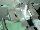
The photo here, of the "ML Midge" case, shows how the rear face is then used in conjunction with a small angle-plate mounted to a lathe face-plate to drill and machine the cylinder bore. The accuracy of the cylinder bore will be governed by the accuracy of the angle-plate, how clean your spindle nose and registers were when the face-plate was screwed on, and how clean the area under the case is. The piece of paper in the photo is an old business-card used to protect the case finish, and to increase friction of the set-up. Card stock generally has a very consistent thickness (naturally, avoid using cards with raised lettering—fortunately I'm not important enough anymore to rate those  ).
).
Back to the original question. I did a little quick, theoretical math based on a "square" (equal bore and stroke) engine of 0.6" (making it just over 2.5cc) and arbitrarily deciding that any mis-alignment that caused the piston to go 0.002" off at TDC might be bad. It turns out that this corresponds to an error of just 0.1 seconds of arc off a perfect right-angle! Now I don't care how good you are, working consistently to this sort of tolerance is insane.
Time to call on real experts. Ozzie Motor Boy David Owen knows engine design and industrial manufacturing. His reply was as follows:
It is an interesting question with, as you say, frightening mathematical conclusions. The diametral crankpin clearance alone on say a 2.5cc engine will be in the region of .01 to .02mm for a hydrodynamic bearing of say 6mm dia. Extrapolate this to a bearing length of say 5mm and a conrod length of say 25mm and it will be obvious that no force exists to displace the piston at TDC until there is an angular error of the major axes in the range of 4-7 minutes of arc.
Add to this some little end clearance plus the effect of a tapered bore and we have some latitude.
However, the consequence of cumulative misalignment will be the tendency for the conrod to run first to one restraint, then to the other, with a consequent reduction in efficiency and an increase in likely wear rates. Given that the crankshaft bends (ref Metkemeijer R.), some builders deliberately introduce an error in the alignment of axes. Others grind the crankpin to a reverse taper. I think both these courses are unnecessary in the simpler type of engines most of us build.
Fortunately, the practicality of all this is not so daunting. If your friend machines the crankshaft axis and some vertical face, generally the backplate sealing surface, at the same setting, he will have a suitable reference to machine the cylinder axis at the optimum 90 degrees.
An angle plate, if used should be checked for truth when mounted on the lathe or under the mill. Any 90 degree fixture on the lathe is easily trued in-situ with a facing cut, given alignment far better than my 4-7' range.
So there you have it. 4-7 minutes is certainly within the scope of home-shop equipment, so we can all stop worrying and get back to engine making. Just be sure things are clean, follow the machining sequence given above, and you will certainly be in the ball-park.
That's it for another month, and astute readers will notice I didn't mention Sparey once. What? Oh bugger. So long 'til next month...
 The Miguel de Racougne Collection
 Editorial