Engine Design for Beginners:
Roy L Clough Jr's Little Dragon
Last update: Feb, 2007
Click on photographs to view in more detail
In the late 40's and early 50's, the magazine Model Airplane News published a few IC engine designs for home construction. With one exception, these were simple designs aimed at first time builders with minimal skill and equipment. Today, the best remembered of these is the Little Dragon designed by Roy Clough Jr. Roy was a prolific contributor of unconventional articles to MAN: IC engine, free-flight helicopter, ducted-fan, etc. All his designs were pioneering—none of these categories were even remotely as well trod as they are today.
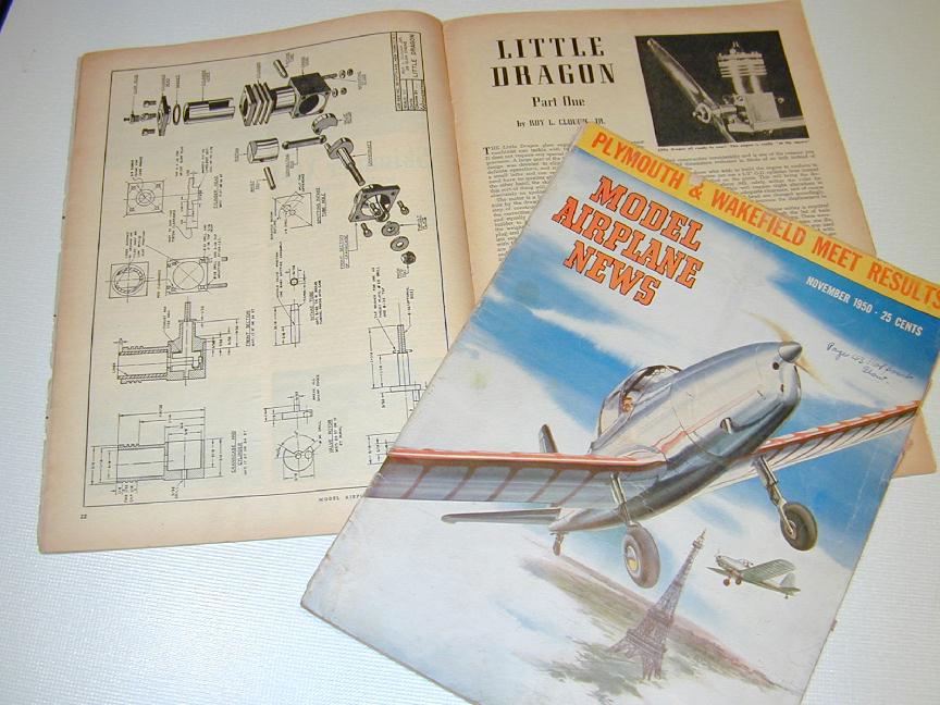
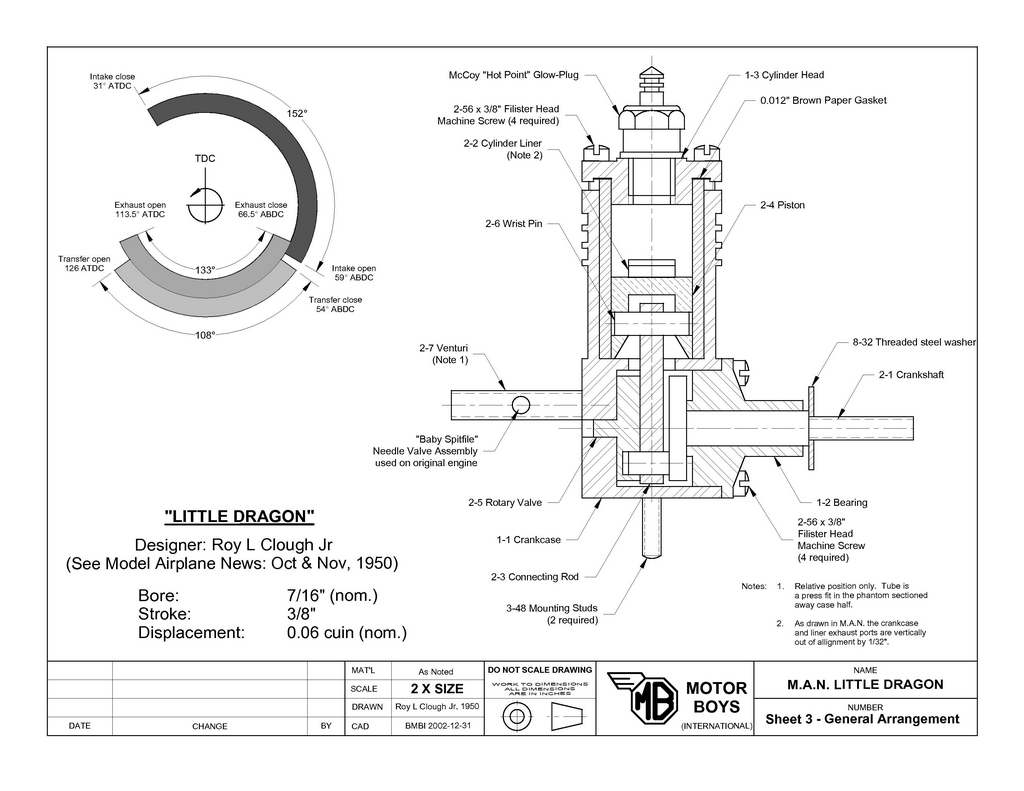 I've talked about the Little Dragon several times before in these pages. The design was serialized over two issues, October and November, 1950. Design wise, it is a plain bearing (actually, no bearing), RRV, glow-plug ignition engine with a bore of 7/16" (nominal) and a stroke of 3/8" for a nominal displacement of 0.06 cuin (1cc). The main crankcase components were made from 3/4" square aluminium bar, with no milling required. The original used a short length of seamless steel tube for the cylinder liner, in which the ports could be cut with a hacksaw and finished with a file!
 Keeping in mind the features we've been working up as desirable for a beginners' engine, the design has good and bad points—some of the latter being unique to features intended as good points (in my humble opinion, naturally). Let's look at the good ones first:
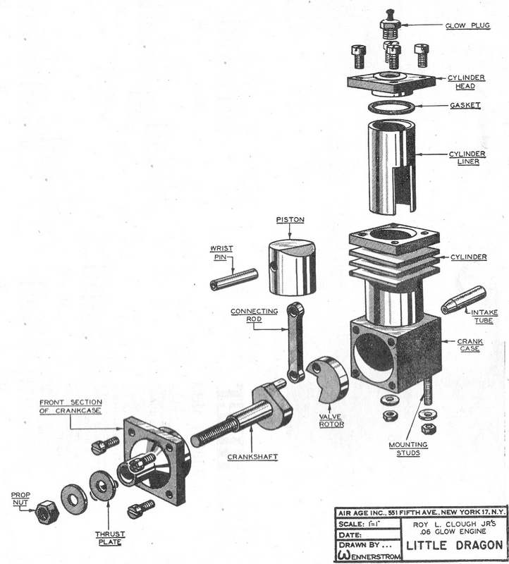
- No castings, milling, thread cutting, nor special cutters required.
- The Rear Rotary Valve (RRV) simplifies construction, and encourages experimentation with inlet timing.
- Glow-plug ignition results in low parts count and lower operating compression than a "diesel", making piston/liner fit less critical.
- It's small in size, so bad parts can be scrapped at little cost in material and time.
- The use of a commercial needle valve assembly (NVA) reduces construction time and removes a tricky assembly from the equation.
- Seamless steel tube liner simplifies construction (maybe; see later), though the liner could still be turned and bored from solid bar stock.
- Clough's answer to the transfer port and passage was unique. The section of tube from the top of the transfer port right down to the bottom of the liner was simply cut away! Thus the liner "port" itself becomes the transfer passage. This has the advantage of simplicity, but there's a But. Ron's Rule #1 (tm) says "slit things always close up". And since it's the bottom of the cylinder we are talking about, we end up with more friction where we actually want less. This can be fixed by more honing, but better if the problem could have been avoided.
- Primary compression depends on achieving a seal between the case bore and the cylinder liner. Too loose and we'll loose charge through the crankcase exhaust opening as the piston descends. And remember that the lower portion of the liner will almost certainly be smaller than the top because it closed up when the transfer chunk was taken out, compounding the problem (regardless of the fact that we've corrected the bore by honing).
- The liner location is set by a blind bore in the crankcase. While this is not that hard to get right within a few thou, any errors will affect exhaust and transfer timing (not to mention that as drawn in the MAN plan, the liner and case exhaust openings miss each other by 1/32" of an inch). Drilling and filing out the slot for the conrod in the floor of this bore won't be fun either.
- The combustion chamber shape is a bit agricultural (see the GA view above to see how far the plug element is located up the threaded plug hole).
- The mounting method places all the out of balance bits some distance above the mounting datum. While a small engine like this is not going to shake that much (the crankshaft does have some counterbalancing), mounting with only two studs will be marginal, rigidity wise.
- The prop driver recommended is just a stamped washer clamped against the end of the shaft journal by the prop and its nut. Additionally, the shaft journal is only 3/16" diameter, reducing in a sharp step to 1/8" for a 6-32 thread. This is delicate and would be easily bent
- You are not going to be able to walk into a model store today and ask for a "Baby Spitfire" NVA!
Ok, I've been a bit harsh. I'm sure lots of modellers were blissfully unaware of all these pitfalls and so made engines that ran just fine to their great delight and pride. But perhaps there was another group who encountered problems they could not diagnose, let alone fix. Let's see what we might do to address the above numbered points:
- There are a number of fixes for this, all involving not extending the cutout to the bottom of the liner. The simplest is a conventional transfer port with its top in the same place, but only as high as the exhaust (3/32"). The transfer passage is formed by milling or filing a flat on the outside of the liner from the bottom of the port to the bottom of the liner. Small sport engines don't need lot of cross-sectional area in the transfer passage, as many adaptations of the Little Dragon have shown.
- Having maintained a constant liner diameter, (2) becomes less of a problem, but careful turning and boring are still required. The liner does not need to be any kind of press fit—in fact this could be bad as it will close up the liner. A firm but removable fit and constant contact all the way down will suffice. Now you see why I dislike liners of this type for a first-effort engine.
- The old design, by using a length of tube for the liner, had no option but to provide a stop for it. This makes the location of the "stop" in relation to the engine crankshaft axis critical, as are the exhaust and transfer port tops in relation to the liner skirt. If the liner were turned from bar stock with a lip on the top, the critical case dimension changes from being the blind bore bottom location, to the height of the case above the crankshaft axis. The cylinder bore can be carried right through into the case cavity, so making a slot for the rod to swing in is no longer necessary either. I'd argue this is easier to make than the former design—although the liner is now more complex. Trade-offs, trade-offs...
- The glow-plug seat could be counter bored to bring whatever modern plug you will be using closer to the inner surface of the head. Some measurement and calculation would be required to set the geometric compression ratio to between 9 and 10 is to 1.
- Odd-ball mounting? Live with it, or increase complexity yet again to have a separate backplate incorporating a bulkhead mount like the EZE series of Little Dragon adaptations (which in consequence adds another four 2-56 blind tapped holes to the construction effort).
- Fit a real prop driver and loose the delicate design. End the shaft where the current transition is, then drill and tap for a 6-32 stud cut from a 6-32 cap head screw. Much simpler, and totally crash resistant. The prop driver could even thread onto the stud, but I'd prefer a taper fit to either a taper turned on the (extended) end of the crankshaft, or a split cone fitted over a slightly reduced diameter extension to the shaft (say 0.156" in diameter for 1/4" long).
- You are going to have to learn to do this someday, so start now. Read about NVA's in the How-To Pages and make a little one of your own.
I do feel bad about all the criticism I've levelled at this engine, especially as I've not built one exactly per the plans to confirm or refute my objections. I should also mention that the original article was well written and concluded with a well thought out set of trouble shooting tips (you can read these in the February 2003 Issue of Model Engine News). The Little Dragon certainly deserves praise for all the similar designs it has sparked, which themselves have spawned children (software engineers love recursion  ). For that if nothing else, Roy Clough Jr deserves to be hailed as providing a land-mark design. We'll look at what others have done with the concept in the next section.
![]()
Back to the Model Engine News Home Page
Please submit all questions and comments to [email protected]