Editorial
These columns just seem to be opening with bad news lately. As I write this, it's Monday in Australia—the Monday after we and the world heard the news and saw the pictures of the loss of space shuttle Colombia and her seven crew. This is tragic: the loss of people always is, no matter where or how it happens. In the same week, eight commuters died in a train wreck in Sydney and all six crew of a Russian transport aircraft perished in a landing accident in East Timor. All these deaths are tragic and my sympathy goes to all the families, friends and colleagues involved. What makes the Colombia's loss more tragic to me is that she represented one quarter of the only reusable spacecraft fleet the world is like to see operational for the next decade or two. I feel sure the seven astronauts would want the program to continue, undiminished and undaunted. I certainly do.
Sparey 5cc — Lessons Learnt and Forgotten
I've just received an email from Peter Munro, an ozzie builder of the venerable Sparey 5cc "diesel" engine (circa 1946: see The Sparey Story). Peter has been building this for a while and saying nice things about my web site and the techniques he has found useful—like the Dave Owen method of contra-piston fitting. After all these nice words, it makes me quite angry with myself that I let Peter down by failing to pass on some important words of wisdom from another Sparey builder, Russell Watson-Will.
Russ built one of these long ago and told me he was less than happy with it as it vibrates like crazy. This I remembered and so Peter did all he could to make the piston light and machine some counterbalance into the crankshaft. What Russ also told me and what I completely forgot to pass on was that he had experienced a big end seizure after just a little running, commenting that in retrospect, "hard on hard" was not such a good idea. He is referring to the steel crankpin and steel conrod. Smaller engines get away with this as the crankpin diameter is small and so the bearing area is small. The 5cc Sparey has a mighty pin, so friction goes up and heat generation goes up, and bad things happen.
The lesson, as I've said before about these early engine designs, is that they are pioneering designs and we've learnt a lot since then. By all means, satisfy your nostalgic urges and build one, but incorporate some of the more modern thinking where it does not show. For the 5cc Sparey, at the very least, an oil hole in line with the rod; better still, a bronze bushing if it can be made to fit, or an aluminum rod (soft on hard = good). Hopefully, Peter will be able to salvage the crankshaft, correct the problem and get his vibrator running again.
Lessons from the Past
While CADing Roy L Clough's Little Dragon, I reread his construction article. The two part article concludes with a diagnostic section that I thought contained some sound observations for constructors of small glowplug engines. I offer them verbatim, without comment:
SYMPTOM: Starts readily, revs up well, rpm drops off when the plug wire is removed.
Indication: Compression ratio too low.
Cure: Add oil and/or nitrate to the fuel, deepen the gasket groove to decrease the head space.
SYMPTOM: Starts very hard with much flashback, but runs well once started.
Indication: Exhaust port not opening soon enough before intake transfer.
Cure: Check liner slots against plan, file more "lead" into the exhaust.
SYMPTOM: Must be flooded to start and will run only on rich mixture.
Indication: Cylinder head, or glow plug gasket is leaking
Cure: Replace gaskets, check surfaces for damage.
SYMPTOM: Kicks violently, runs in short high speed bursts, kicks off prop, stops suddenly.
Indication: Compression ratio too high.
Cure: Reduce compression ratio by shaving down inserted "plug" portion of cylinder head, or try high compression fuels with a cold glow plug.
SYMPTOM: Starts easily, holds up speed when wire is removed, leans out well, then gradually dies out.
Indication: Motor not yet broken-in, probably overheating.
Cure: Use heavy, low pitch prop and run motor as rich as it will take for ten to fifteen minutes, then try again.
General: Watch for unusual bugs, clogged fuel line or needle, tanks not vented correctly, loose prop, bad plug, loose wires, insecure mounting, evaporation weakened fuel. Use a port prime to start engine.
 Some good observations there and a curious bit of vernacular usage. Today, "bug" has entered the language as a general term indicating a problem, thanks to the ubiquitous nature of computers in our society and the problems we encounter daily with unexpected behavior in our software. This usage of the word is attributed to Grace Hooper (later Rear Admiral Hooper), who discovered a dead moth in the contacts of a relay in the US Navy's Mark II computer at Harvard University. She entered the term bug (and the dead critter) in the log and the rest is history. This was 1946; Roy Clough's article was published in 1950. I have no idea if he worked in the field, or if the term came to him from elsewhere. That it passed the editor of MAN as a term that readers would understand says it must have been in common usage by then. Amazing.
More CAD Adventures
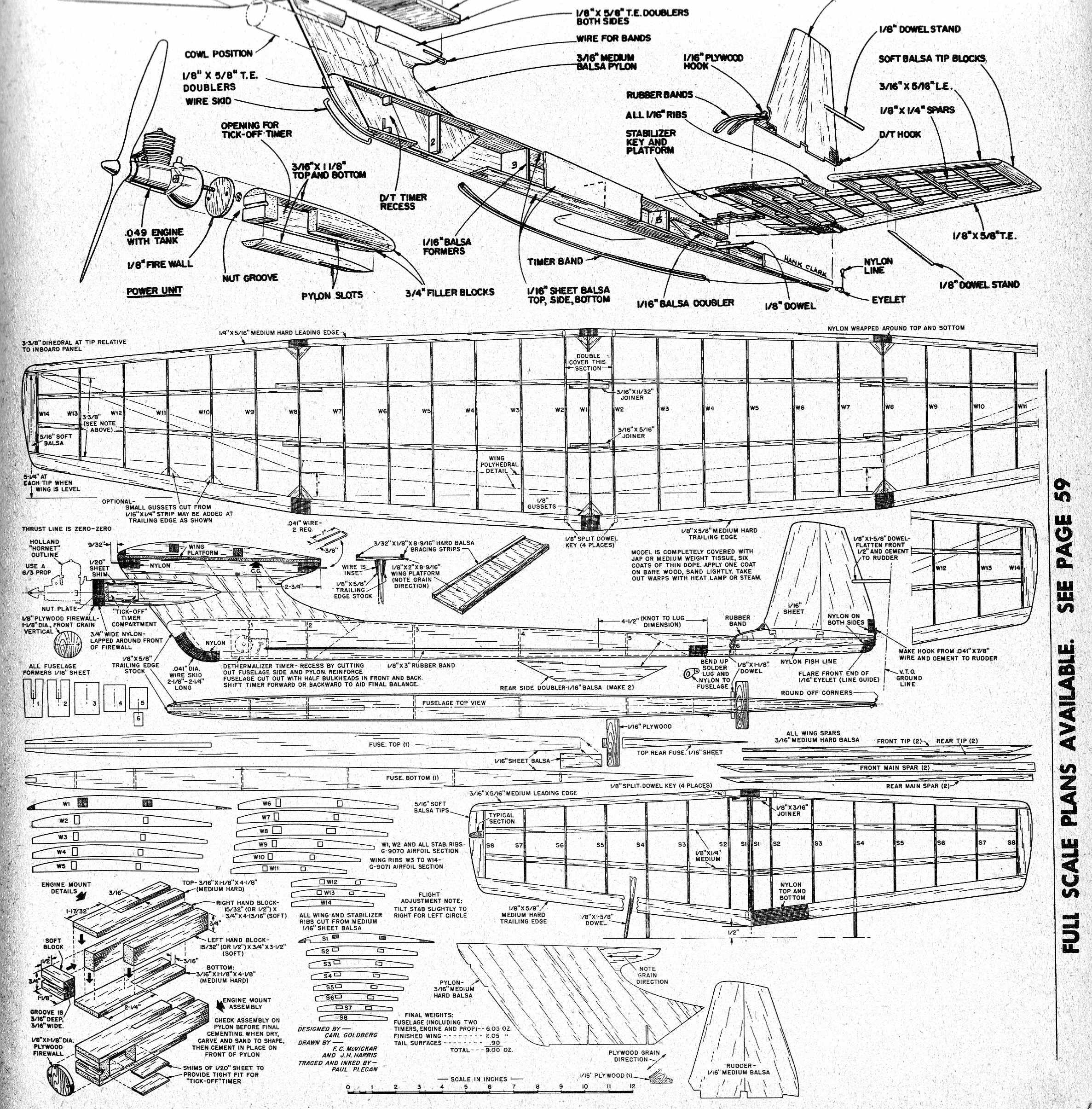
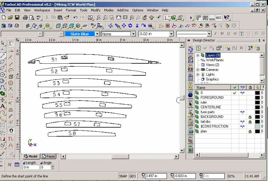
Last month I mentioned the 3D CAD course I had bought and worked through from CadCource.com. Part of the exercises showed how to take a scanned image, accurately scale it to size, then trace over the image. This caused wheels to spin and dreams of an F1J model dance in my head. I've a soft-spot for Carl Goldberg's Hi Thrust Viking from 1961 and still have a tatty plan from a kit of that vintage. Being a kit plan, it has outlines, but no parts and came from days well before I began tracing die-cut parts onto the back of plans against future needs.
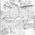

So out came the appropriate issue of Model Airplane News (May 1961) and a scan of the reduced scale plan was made and saved as a JPG file. Sections of the "plan" containing ribs were snipped off in a paint program and saved as BMP (bitmap) files to be loaded into Corel Trace (which comes with TurboCAD 8). This program is able to convert the gray scale images into all black and white, then use a variety of algorithms to convert the bitmap image (chunky) into vectors (thin, but a bit scratchy) which are saved in DXF format (the defacto exchange format for CAD drawings).
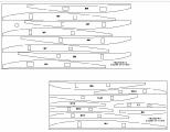
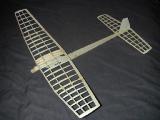
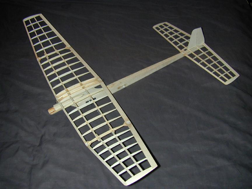
Luckily, MAN magazine plans of the era usually contained a 12" ruler for those scaling up to full size. This was loaded into TurboCAD (as DXF) and measured to determine the scaling factor. The other DXF files were then loaded and their X-Y sizes "scaled" to 100% and placed on a locked layer. It was then a simple matter to "trace" over the parts and accurately cleanup the drawing. The Viking uses tapered spars that fit through the middle of the ribs. The wing tapers at leading and trailing edge and has different taper for the tip and inner sections of the polyhedral wing. Hence, all ribs are different sizes and all spar holes are different sizes—a real test for the technique. The parts were arranged on sections to represent 3" and 4" wide balsa sheet with minimum wastage, then laser printed. The A3 (letter) size prints were ironed onto balsa to transfer the clean, sharp images for cutting out. The result? The wing and tail parts slid together just as perfectly as I remember the kit parts doing. I'm immensely pleased with the result, the technique, the course that taught it, and myself! 
Magazines and Books of the Month
Would you believe? Not a damn thing arrived this past month.
Needle Seats
I've been thinking about needle valves and spray bars as I seem to have had to make several over the past month for my own engines and some restorations for friends. When I'm doing a replacement for an old engine, I try to maintain the external appearance, but have now settled on an "internal" design and method of manufacture that gives good, consistent results. Before this, I had made some that worked, but were difficult to adjust with any predictable results—and some that caused the engine to stop if you so much as touched them, though the engine could be restarted at the same setting that stopped it!
For the needle itself, I use hard, so-called "music wire"—the sort sold by hobby stores. Real music wire comes in coils and would be just about useless for our purposes. The needle is formed off-hand, first against a grinding wheel, then a sanding disk (on the other end of my bench grinder), then on a Scotch-Brite (tm) buffing belt (same end of bench grinder). The needle looks good, but is not a precision taper; ie, the point is almost certainly not on the axis of the wire, and the taper sholder will not be diametral—rather some kind of crazy ellipse. Used with a straight-thru hole in the spray-bar, such a needle would give poor results as mentioned above, but used with a seat, it's just fine.
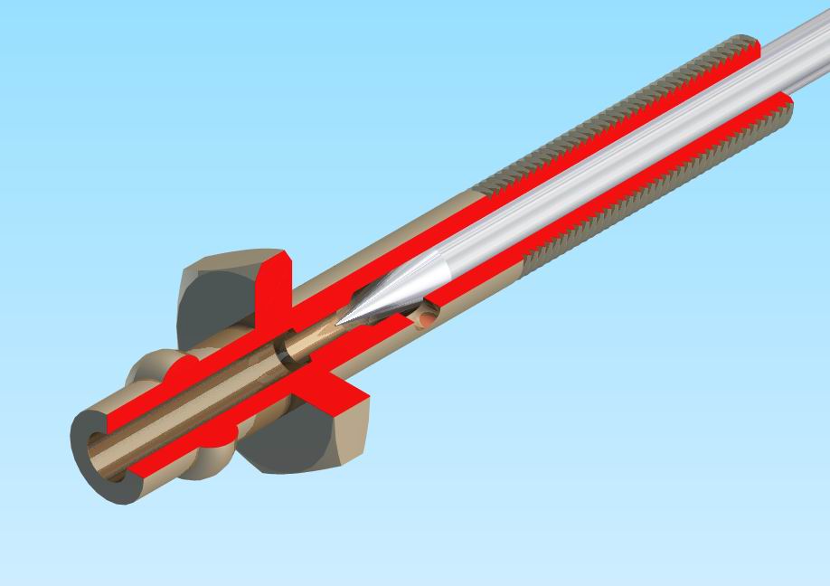
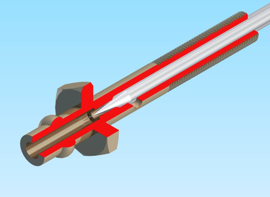
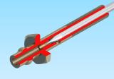
The TurboCAD 3D cut-aways below show the arrangement required. Let's say the wire is 1/16" OD. First I turn the spraybar to shape on the side the will be threaded, then form the thread with a die. Always do this before drilling for the wire as the drag of the die is considerable and could distort the brass if it were already cored. Next drill the brass spraybar with a number drill that is just less than 1/16" to a point just beyond where the jet hole will be. Follow up with a #60 drill in the same hole for 1/8" to 1/4" of additional depth. The #60 bit will be centered by the point left from the 1/16" bit. At this stage, the needle wire should not fit in the hole.
In all these drilling operations, "peck" out the hole. I have a sash brush in my left hand and advance the tailstock with my right. Drill into the work about 1/16", withdraw completely, brush off the chips, and peck in again. If the drill ever squeaks, the flutes are loading up with chips and the drill is about to break, if it hasn't already. The peck method does not take long and keeps the core central. The internal finish will be cleaned up at the next step.
Make a D-bit reamer from the same music wire stock as the needle by grinding away 1/2 the diameter for about 1/8". The end should not be square, but raked about 5 degrees so normal clockwise rotation has the "point" leading into the hole. Use this to ream the last couple of thousandths from the hole down to the seat area, pecking away as before. The wire should now be a close sliding fit with no air leaks.
With the spraybar still on the stock, transfer to the drill press and cross drill #60, one side only, to form the jet. The fuel tube side of the bar can now be formed and center drilled with a fine #1 center drill, followed by a 1/16" bit to meet up with the #60 axial hole so that the seat passage is maybe 1/16" long.
 The idea is that all fuel metering occurs around the seat and the point. If the point is a bit eccentric, it does not matter. Down-stream, the needle shoulder never comes near the spraybar jet, so an elliptical needle shoulder does not matter either. The close, reamed fit of the needle prevents air being sucked in from the thimble side and you have a needle that responds well and consistently. Of course, we are talking sport class engines only here. High performance stuff is another matter, but the general idea of metering at a shoulder rather than the jet still applies.