M.E. Heron
Updated: April 2007.
 |
 |
| Name | Heron | Designer | Walter Kendall (Marown Engineering) |
| Type | Compression Ignition | Capacity | 0.97 cc |
| Bore | 0.424" | Stroke | 0.420" |
| Production run | unknown | Country of Origin | Isle of Man |
| Photo by | Ron C | Year of manufacture | 1960 |
Background
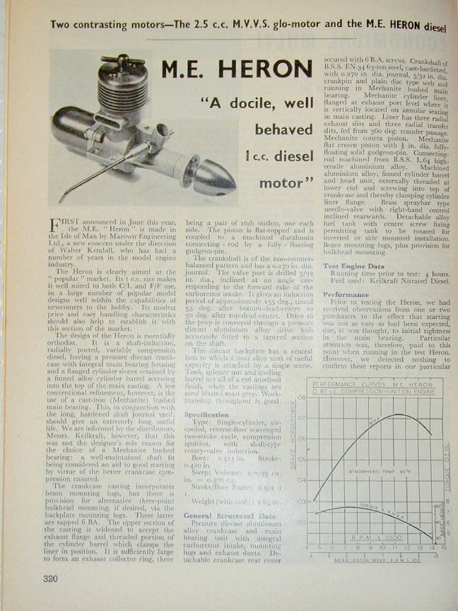
In the about the middle of the year 1960, "Marown Engineering Ltd" of Glen Vine, Isle of Man—better known and universally referred to as "M.E."—released the first of their two compression ignition designs by proprietor Walter Kendall. This was the 1cc Heron, to be followed two years later by the 1.5cc Snipe. The Heron was described in the modelling press as "A docile, well behaved 1 cc diesel motor" [1].
Marown expanded into aerospace, principally sub-contracting to Rolls-Royce. Later, Kendall and Marown transitioned to petro-chemical instrumentation through a subsidiary company, Kenmac Controls. Both companies were later acquired by the Delta Corporation [6]. Before this, the model engine line in its entirety was sold to "Moore Engineering" who continued production of the two engines. This company was operated by Peter Moore who was also associated with the PMC Imp and the earlier EmBee engines, the latter in conjunction with one Mr. Bailey (hence, "em-be"). Anyway, if the standard of PMC is any indication, Moore's involvement didn't augur well. Lastly, the M.E. engines were made by Mayglen Engineering Ltd, Market Place, Peel IOM [2] (the precise dates for these name and ownership changes are not known).
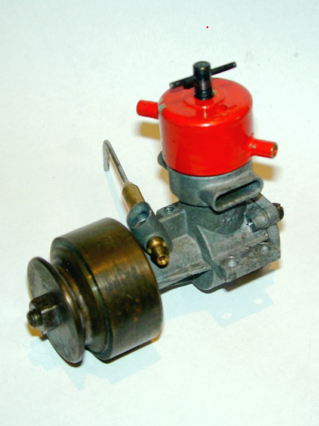
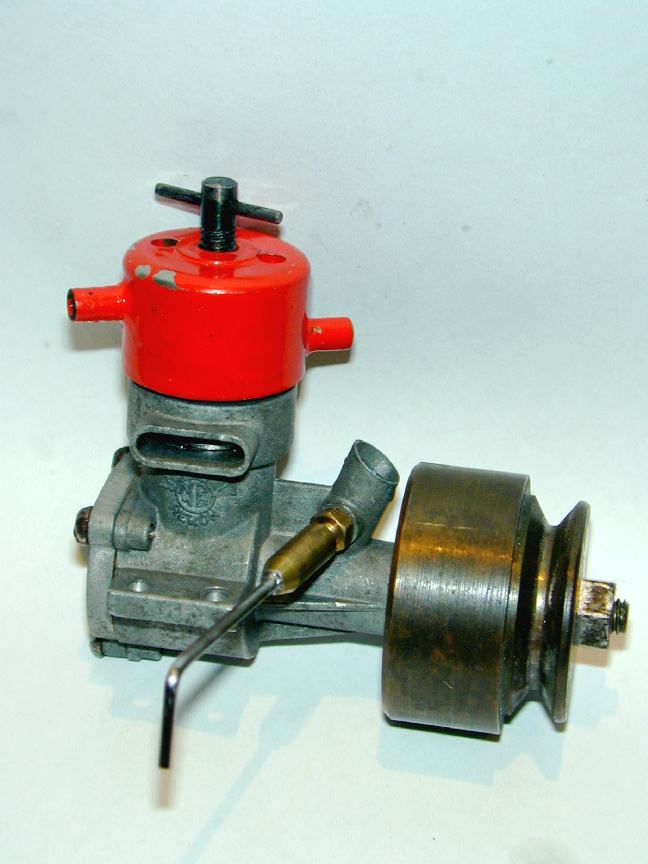
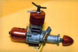
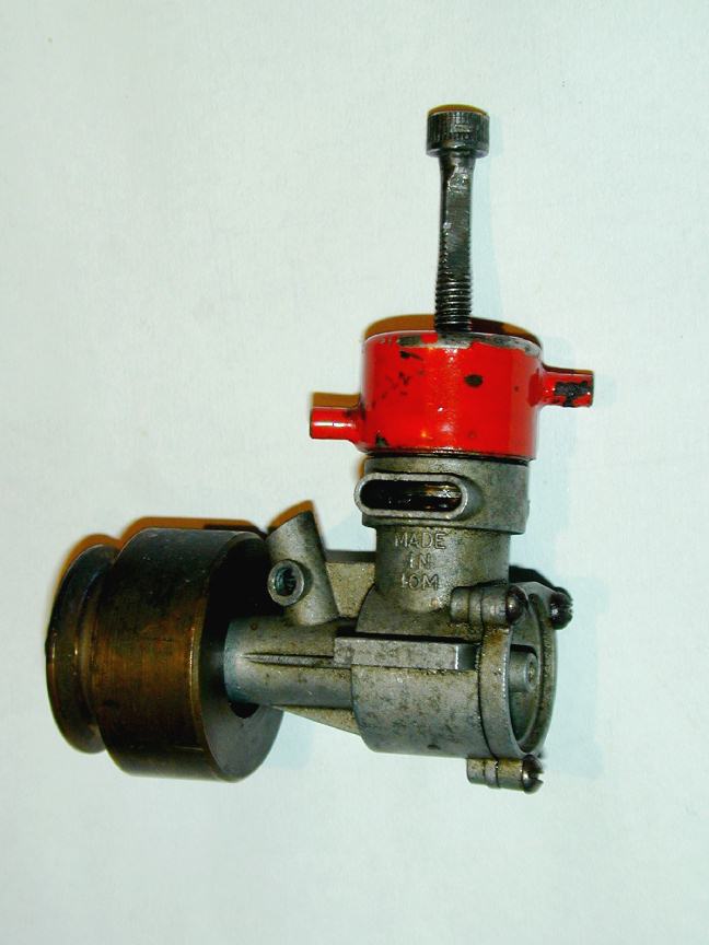
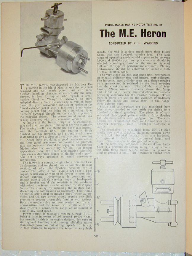 The engine pictured above is, quite obviously, one of the marine versions, M.E. having released both types simultaneously for both of their engines. In 1960, the standard version was priced at 47/3 (UKP 2.36 in today's money); the marine version was significantly more expensive at 64/11 (UKP 3.25). Ron Warring's review in the October 1960 issue of Model Maker [3] began by saying ...an extremely well designed and well made power unit with most pleasant handling characteristics--virtually the ideal answer, in fact, to anyone who regards the small marine diesel as "fussy". He also notes that the marine version dispenses with the rear mounted fuel tank and die cast prop driver, the 1-1/4" flywheel being mounted directly on the crankshaft taper.
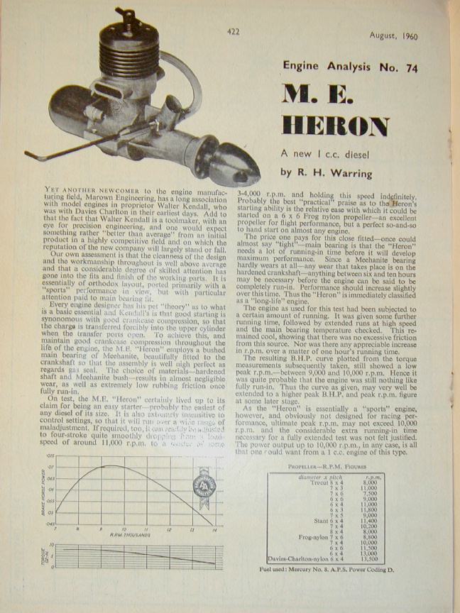 Two months earlier, Warring had reviewed the "aero" version of the engine for companion magazine, the Aeromodeller [4]. Despite what must have been a great temptation, the two articles do not seem to share any common text, although they say essentially the same thing. In this review, Warring notes that Walter Kendall had been with Davies Charlton in their earlier days and was a toolmaker by trade. Certainly there is a degree of outwards similarity between the Heron design and the DC Merlin, Sabre, and Spitfire designs. The internal aspects are similar as well (although to be fair, there are a limited number of ways to design a small diesel for economic quantity production), but there are enough deviations to show that the designer wanted to make improvements, chief among these being the use of a close-fitting cast-iron crankshaft bush.
 The uncredited review of the engine in Model Aircraft (probably written by Peter Chinn) [1], restates Warring's observations regarding a pet theory of the designer very closely. So closely in fact that one could begin to suspect that a press release lurks in the background. Specifically, all three make mention of Kendall's strongly held belief that good starting was assisted by maintaining better crankcase (primary) compression, and that this could be achieved through use of a close fitting and well-maintained bushing on a long, hardened shaft. To this end, the engine featured a cast-iron bushing, honed to a very close fit on the shaft. To keep weight down, the bush was very thin, so to prevent distortion during assembly, the case was pressure die-cast around it--with an additional advantage through the reduction in the number of operations and set-ups required to finish the cases (cast-in bushed were not a new innovation, having been used a number of US engines such as the fixed compression "Mite" diesel). Warring observes in both of his articles that the closeness of the fit, combined with the long-wearing nature of the cast-iron bush may require an extended break-in period, which could be as long as eight hours before peak performance could be expected!
Construction
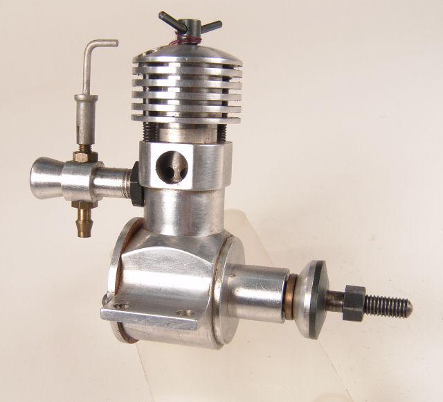
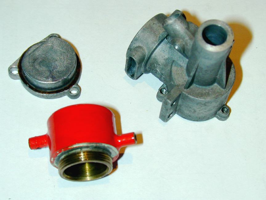 The Heron case, backplate, and prop drive washer (on the aero version) are all pressure die cast. Delicate engraving places the winged "M.E." logo with the word "Heron" in curved text under it on the right side of the case; the left carries the text "MADE IN IOM". The backplate is secured by three 6BA screws and is relieved on its upper side for piston travel at BDC. It is fitted with a tapped spigot for the long 6BA tank retaining screw. The cooling jacket for the marine version is conventional for the time: a brass muff with a water jacket soft soldered on the outside. The air-cooled head was initially supplied, as seen in the review photos above, with two blind holes in the top for a pin-spanner (supplied, according to the early adds). Later versions inspected have flats machined on the sides of the cooling head top for the same purpose, presumably as an economy measure. The compression screw thread is 2BA--the same as the crankshaft itself. Now, a thing worth making careful note of: this particular example of the engine has no bushing whatever! After all the big wind-up made in the articles cited, we note that the shaft is running in a hole reamed direct in the case, and slightly off-center at that! I can only surmise that this is a late model after the firm had changed hands.
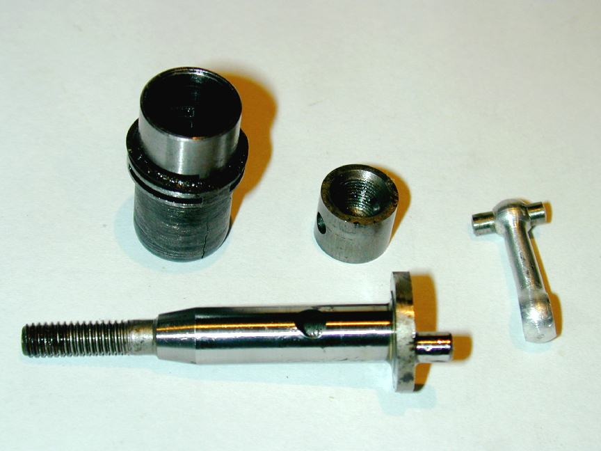 The cylinder design is very standard for the period (similar to the DC engines mentioned earlier, and the ED Racer). It is flanged, with 3 exhaust ports cut in the flange. Directly under these are three transfer slits. This arrangement gives very mild porting as the exhaust must be fully open for a period before transfer can start, significantly limiting the available transfer period if the exhaust timing is to be kept to a reasonable value. The liner locates in the case on the flange OD; the lower portion fitting in an oversize bore in the case to provide 360 degree transfer. It is held in place by the head (or cooling jacket in this case) which screws into the exhaust collector ring of the crankcase, just like the AHC Diesel. The piston is a little unusual in that it is flat topped and rather thick walled for all its length. It is threaded on the inside, presumable for mounting while grinding/honing. The contra-piston has a similar internal thread. Both pistons are cast-iron (stated in the reviews as being "Meehanite"--the trade-name of a close-grained cast-iron material).
The cylinder liner, as stated in all three reviews, is also machined from "Meehanite". The combination of cast-iron running in cast-iron can be quite long wearing, but a cast iron cylinder is rather delicate. If you examine the top of the cylinder in the photo above, you will easily spot the jagged crack that has robbed this engine of most of its compression, and all of its running ability. It is worth noting that the Snipe was significantly different internally, with a hardened steel cylinder, fluted internally with three milled transfer passages that overlapped the exhaust ports significantly [5].
The rod is a "dog-bone" type, turned from aluminium alloy, and fitted with a fully-floating wrist (or gudgeon) pin of 1/8" diameter. The ends are rounded and as the port slits are small in comparison, no great danger exists that a jam might occur. In contrast, the Snipe's piston (shown here) was grooved for a thin wire pin-retaining circlip as there was an almost certainty of a floating pin jamming in the internal transfer flutes. Motor Boy Dave Owen has convinced me that this is a bad idea on engines where the transfer ports overlap the exhaust. The reason being that as the piston descends, and well before the exhaust opens, the circlip groove will briefly connect transfer and exhaust ports. During this period, the crankcase is open to the atmosphere and it is possible for higher than atmospheric crankcase pressure (and the new charge) to vent via the exhaust. The duration will be small, and obviously such engines run, but it's something to consider, especially from a designer who had made such a big thing about retaining crankcase compression through close shaft bushes. One Taipan also used the circlip wrist-pin retainer idea. Other designers have used a press fit pin, although these tend to distort the piston requiring extra running-in and making disassembly and re-insertion uncertain. The Pepperells came up with an innovative and unique solution: soft-solder it in!
The shaft is very standard: case hardened and ground with a full-circular web, ie, no attempt at balancing. The jury is out on this one, at least for small "sport class" diesels. Some did, some don't.
 |
 |
 |
 |
Performance
The reviews of the Heron give the bore as 0.424", with a stroke of 0.420" for a capacity of 0.059 cuin, or 0.97 cc. The bare weight of the marine version is 6-1/2 ounces, of which 3-1/2 oz is flywheel. Much of this weight is close to the flywheel axis which Westbury says is not ideal. The aero version weight is given in [4] as 2.4 oz, while [1] states it as 2.65 oz. Performance wise, the Model Aircraft review found the maximum BHP to be 0.072 at 11,500 rpm. Aeromodeller got 0.071 BHP at 9,500 rpm, but felt their example of the engine would benefit from more running.
Model Aircraft [1] thoughtfully munged their data to produce a figure useful in comparing engines of different capacities, namely the Specific Output. This is the power produced per unit of displacement; in this case, 74 BHP/litre. Compare this with the figure of 99 BHP/litre for the M.E. Snipe 1.5cc diesel stated in ref. [5] (As mentioned in the ED Bee review, measuring power output from small engines is highly problematical and unless all your figures come from the same test-rig, comparisons may be rather misleading. The specific output figures quoted are from the same tester, so there they have a chance of being actually comparable.)
Specific Consumption would be even better, but no regular model engine test I've ever seen provides that. When available, this is stated in fuel weight consumed, per unit of time, per unit of power. For example, lb/hr/hp, or lb/hr/lb (pounds of fuel consumed per hour, per horse power produced, or alternately, per pound of thrust produced; metric folk may substitute kilogrammes and Joules, or something...) The use of the fuel weight rather than volume is necessary because fuel volume changes with temperature, but the energy of a given mass is constant--although at model sizes, the difference would be insignificant. Thrust specific consumption could in theory be measured by a simple spring balance, a burette, and a stop watch and would give a very useful means of comparing performance, assuming the prop was selected to maximise static thrust.
Restoration
 As received, the engine was missing the NVA (naturally!), and was fitted with a most unusual compression screw. A bit of gunge, some spot corrosion on the aluminium case, the lack of compression (via the cracked liner), and a slightly bent conrod testify to its past life as a marine thumper--one can inflict far more damage with two hands, a flywheel and a pull-cord than you can with a prop and a finger. The cap-head screw poking out of the cylinder head should have been 2BA, but turned out to be a 10-32. This substitution one can get away with, almost. The major diameter for a 10-32 is 0.190" and the pitch, obviously, is 0.031" (the inverse of 32). A 2BA screw, being metric, would be 4.7 mm, or 0.185" major diameter, and 0.029" pitch (31.4 TPI). So with a little persuasion, the two can be mated, though the softer one will never be the same afterwards. In this case the softer one was the head, so the replacement comp screw was made with the 2BA die opened up as far as possible in a vain attempt to achieve a good fit.
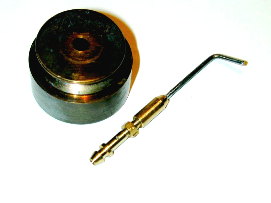
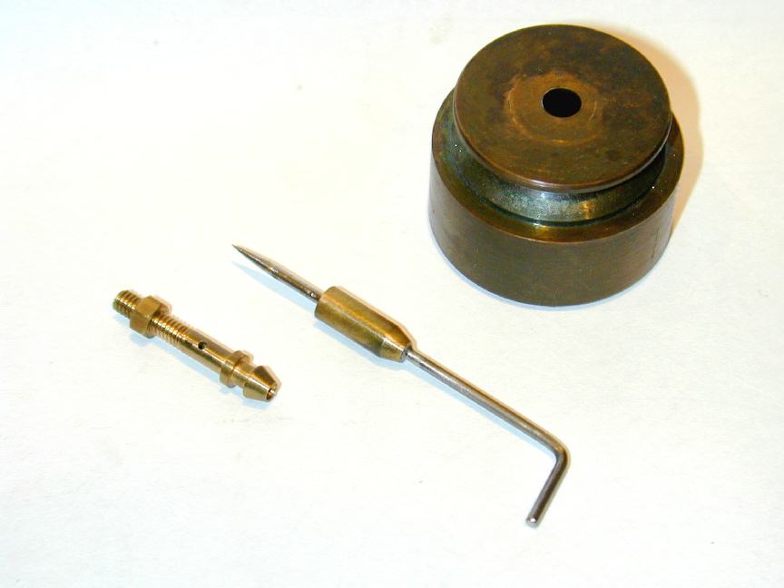
The making of a replacement needle valve and spray-bar was covered in detail as the Tech-Tip for November 2004. This resulted in a bright and shiny (shite and briney?) replacement which just looked plain *wrong*, and was likely to go on looking wrong for the next four or five years. So with nothing but the purest of intentions, the collective wisdom of the Motor Boys was canvassed to see if an accelerated way of aging of brass was known. Although it's perhaps difficult to see in the before (needle screwed to spraybar, left) and after (needle and spraybar separate, right) shots here, the results are actually quite acceptable and the NVA has just enough "age" patina on it to not look totally out of place any more.
To close off on the Heron, it is known that literally sacks full of Marwon bits have appeared in the UK from time to time, and as M.E. did not stamp serial numbers on their engines in some hard-to-duplicate fashion, an engine assembled from bits may be hard to tell from the real thing--so caveat emptor and don't catch auction fever.
References:
| [1] | anon: Engine Tests: M.E. Heron, Model Aircraft, Volume 19, Number 233, November 1960, Percival Marshall & Co Ltd, p320. |
| [2] | Owen, DC: Private email correspondence, October 21, 2004. |
| [3] | Warring, RH: Model Maker Marine Motor Test No. 26: The M.E. Heron, Model Maker, Volume 10, Number 118, October 1960, Model Aeronautical Press Ltd, p502. |
| [4] | Warring, RH: Engine Analysis No. 74: M.E. Heron, Aeromodeller, Volume XXV, Number 295, August 1960, Model Aeronautical Press Ltd, p442. |
| [5] | Chinn, P: Peter Chinn tests the M.E. Snipe 1.5 c.c. Diesel Motor, Model Aircraft, Volume 21, Number 255, September 1962, Percival Marshall & Co Ltd, p272. |
| [6] | Private email communication from Carl C Kendall, son of designer and manufacturer, Walter Kendall. |
![]()