Contents:
- Introduction
- Mainly historical
- Fifty years of experimental work
- Cylinders
- Port design
- Mechanically timed admission
- Applications of rotary valves
- Crankcase compression
- Piston design
- Composite pistons
- Deflectors
- The "Zephyr" 2-1/2 cc engine
- Piston head transfer valve
- Crankshaft design
- Bearings
- Connecting rod bearings
- Connecting rods
- Flywheels
- The Atom V engine
- Phoenix 15 cc engine
- The Busy Bee 50 cc engine
- Carburation and combustion
- Combustion chamber design
- Twin two-stroke engines
True enough, I have not produced a new design
for a two-stroke engine for a long time. This is
not due to lack of interest, or even ideas for development
of design; but the fact that miniature two-strokes have
been produced commercially in great
numbers and variety, and are readily available to
those who want them, makes it more difficult to
persuade model engineers to undertake their construction.
Let me make it clear that I have nothing
against the ready-made engines or those who use
them for propulsion of various kinds of models;
most of them work very well, and provide a source
of power far more efficient than anything previously
available. They also enable impatient enthusiasts to
buy time, to say nothing of the elimination of hard
work and skill involved in construction.
I have on many occasions given technical assistance to the
manufacturers of engines, and many of
the features of design which are now common practice
were first applied by amateur designers, among
whom I venture to include myself. But I have also
tried to encourage individual constructors (when
you come to think of it, this is really what model
engineering is all about), and this is sometimes
interpreted as a private vendetta against commercially
made engines. Such an idea is clearly absurd, as
the number of engines likely to be made in home
workshops, even at the most optimistic estimate,
could never be a serious menace to manufacturers.
In same respects, any individual enterprise may
even be helpful to them, by demonstrating the
application and possibilities of miniature engines to
the uninitiated more convincingly than the most
expensive publicity campaign.
In this review, therefore, I propose to concentrate
on the home-produced two-stroke, and trust
that I shall not offend any persons or parties by
doing so. Of necessity, I propose to indulge freely
in reminiscence (or as some may consider, ancient
history) about two-strokes in general and miniatures
in particular, but I shall also do my best to consider
modem problems and to answer some of the innumerable
questions which have been put to me by readers.
One of the questions I am very frequently taked
is "Who invented the two-stroke?" This is a
very simple question, but, like many such, not really
so simple to answer. The early "atmospheric"
internal combustion engines, such as the Hugon and
Lenoir, were two-scokes, in the sense that combustion
took place once par complete revolution of
the shaft, i.e., two strokes of the piston. But these
engines were completely superseded by the Otto
engine, in which the mixture charge was compressed
in the cylinder prior to ignition and nearly all later
i.c. engines follow this principle, though not
necessarily the identical working cycle. This includes
two-strokes, in which it became necessary
to incorporate some form of air pump, compressor
or blower to force the charge into the cylinder as
distinct from sucking it in during one complete
piston stroke, as in the Otto cycle engine.
Most authorities credit Dugald Clerk with the
invention of the precompression type of two-stroke,
and it is probable that his engine was the first of
such to be employed to my great extent. But
Clerk's patent of 1881 was predated by that of
James Robson in 1879. Besides individual features
of design, the major difference between the two
engines was that Clerk employed a separate pump
cylinder for charging, while Robson utilised the
reverse side of the piston, in a cylinder like that of
a double acting steam engine, for the purpose.
Before the end of the nineteenth century, many
individual inventors filed patents for "improvements
in or relating to" two-stroke engines, but
whatever their merits might been, manufacturers
have not been enthusiastic about any
departure which involves complication of design
or construction. Much the same applies to the
innumerable attempts to improve thes engines in
more recent years and, apart from engines of quite
large size, the simple three-port engine is still predominant,
though it has bean considerably improved
in detail, and its performance has been enhanced by
long and patient development by many individual
experimenters.
As a rival to the four-stroke engine, however, the
two-stroke has many limitations and disadvantages.
Although it is sometimes thought that an engine
which fires twice as frequently as a four-stroke
(other things being equal) ought to produce twice as
much power, this is rarely, if ever, achieved in practice,
and it is even difficult to attain parity of performance.
Two-stroke engines have to answer for
many sins; they usually more noisy, less
economical, and more difficult to control than font-strokes;
in some cams they are liable to overheating,
tricky to start add generally temperamental.
Sophisticated engineers, for the most part, have
tended to regard two-strokes as unworthy of serious
consideration, and have neglected them in the
general scheme of engine research. I have even
encountered a rooted opposition to them, and have
been told "We wouldn't have anything to do with
two-strokes at any price!" This may partly
account for the fact that in the development of
full-size aircraft engines, few attempts have been
made to use a two-stroke engine, though some
promising designs have been evolved at various
times. The late Professor A. M. Low once
facetiously remarked "These wretched little (two-stroke) engines
have no right to existence; they
ought not to work at all, but, surprisingly, they
do!" At the time when I became interested in
motor cycling, two-stroke machines were considered
definitely inferior to four-strokes, and, in fact, their
riders were regarded as declasse. Things are very
different now, and over 90 per cent of two and
three wheeled vehicles have two-stroke engines.
I have always considered that the two-stroke
should be given due consideration in technical
literature, if only because most mechanically minded
youths obtain their first introduction to i.c. engines
by way of two-strokes of some kind or other. But
many of those who use them have no more than
a vague idea of how they work, to judge by some
of the very naive questions they ask about them.
In common with four-stroke engines, miniature
two-strokes in the early days were not only few and
far between, but also of dubious design, and no
information on their construction was available.
The first of my engines to be described in M.E. was
Atom 1, built in 1925 with the intention of installing it
in a half-scale model of the Comper CLA3
light aeroplane constructed by Cranwell RAF
Apprentices. The engine ran quite well, except for
sparking plug trouble (the miniature plugs then
available were not at all satisfactory), but the 'plane
never became airborne. As a "guinea pig" for
further experiments, however, Atom 1 served a very
useful purposes though it was too large to suit the
popular sizes of model aircraft. I tried to stimulate
interest in the development of suitable engines, but
found it extremely difficult to persuade
aeromodellers that anything better than rubber motors
could be produced for this kind of work. It was
not until the early '30's that I succeeded in
obtaining the co-operation of (then) Capt. C. E. Bowden,
and was able to prove that engine-powered model
aircraft were practicable.
During the 1920's there was a great upsurge of
interest in the development of model speed boats,
and although flash steam was then regarded as the
most efficient means of their propulsion, petrol
engines were beginning to challenge their supremacy.
From over the channel came that wizard of
two-strokes, M. Gems Suzor, to astonish the natives
with the performance of Canard and, later, Nickie
11. The M.P.B.A [rc: Model Power Boating Association]
and the Modele Yacht Club de Paris
got together to set up an International class
of petrol-driven speed boats with engines limited
to 30 c.c. capacity, and this was undoubtedly a
milestone in the history of model power boats.
This application of small petrol engines offered,
at the time, a more promising field for their development,
and by taking advantages of lessons learnt by
experiments with Atom I, I designed an engine of
30 c c. capacity, having features which I considered
suitable for efficient speed boat work. It was named
Atom II, and gave excellent results on the test
bench, but, unfortunately, ended its career in a
spectacular breakdown under load, due to a faulty
crankcase casting. Its successor Atom III, of more
robust construction, though similar in its general
design, withstood the most stringent tests, and
produced speed and power beyond my expctations;
I still regard it as one of the most successful of my
two-stroke designs.
Most model exponents of petrol-driven speed
boats, however, preferred four-stroke engines, and
regarded two-strokes with suspicion. I can remember only a
very few of them who had any faith in
the possibility of achieving high boat performance
with a two-stroke engine. Notable among them was
that great individualist from the North, Mr A. D.
Rankine, whose Oigh Alisa dynasty of boats put up
spectacular performances; another was the late
Bill Rowe, of the Victoria M.S.C., whose boats were
mostly noted for high speed, long distance endurance runs.
My own attempts to produce results in
this sphere were handicapped by lack of knowledge
of hull design, and usually ended in crashes or
capsizes.
I shall refer later to the particular features of
these early engine designs, which, although now
becoming antique, are still capable of producing
good results and for this reason cannot be dismissed
as completely obsolete. While I have never claimed
brilliance of design or super-efficiency in any of my
engines, I think I can justly claim that many of their
features, in structural methods and functional working parts,
were innovations which have influenced the progress of
design even up to the present date, including that of
commercially built engines. I have always sought to
exploit as fully as possible the potential
advantages of two-strokes, including low frictional
or other mechanical losses, and low weight,
while reducing their inherent disadvantages such
as imperfect charging and scavenging.
Up to and during the last war, I made many experiments
in design of two-stroke engines from 50 c.c. down to
2-1/2 c.c., most of which, but by no means all,
have been described in M.E., and nine of these designs
are still available from the M.E. Plans Dept.;
but others, and mutations (or mutilations) of them,
have never been recorded, beyond references to them in a
series of articles in Improving the Two-stroke
published during the war years.
When the decision was made to produce an aircraft engine
smaller than the Atom Minor 15 cc, the opinions
of interested aeromodaillers were consulted, to ensure
that the engine would be well suited to their requirements.
Not only the capacity of the new engine, but also relevant
features of in design and construction, and the mode of
installation in the airfrme, were discussed in detail.
The outcome of all this was a specification for an engine of 6 cc,
which was described as the New Atom Minor,
though I preferred to class it a "Mark II,"
became the term "New" has a short-term significance,
and often comes all too soon outdated or unfashionable.
Though this engine fulfilled its puprpose, and gave good
results in model aircraft of managable size, it was soon
brought home to me that there was vary little interest
in the construction of engines for this particular
purpose. Ready-made engines were becoming available,
and have since become almost universal, not only
for the propulsion of aircraft but also for
other kinds of models.
The first model racing car built by Jim Crankshank was,
I believe, powered by a Kestrel, and the design formed
a basis for many modified and improved engines by other
individual constructors. (Fig. 4.)
The dominant component in an enclosed engine
such as a two-stroke is (in most cases) the
crankcase, which may incorporate other items
in order to reduce the number of parts, reduce
all-up weight, or simplify machining operations.
In the early days of motor-cycles, a form of crankcase
was developed which was well suited to the enclosure of
internal flywheels; it was split on the vertical
transverse centre-line, with main bearings in the two
halves, and machined flat on the top to form a cylinder
mounting platform.
This design has persisted, even when its original
purpose no longer holds good, but I have rarely
used it in two-stroke engines, as I consider
that it involves unnecessary problems
in machining the concentric register of the two halves, and the
cylinder seating and register after bolting the halves
together.
The blind-ended or "cup-form" crankcase is
suitable for overhung-crank engines which do not
need a power take-off on the end remote from the
flywheel. But, the "barrel-form" crankcase, open
on both ends, may be better suited or even necessary
for assembly in certain cases. The former type
was employed in the Atom I engine, in which the
crankcase was extended upwards above the level
of the exhaust and transfer ports; this was done
mainly to reduce engine weight as much as possible.
A cylinder casting (in iron) with ports and passages
in it would inevitably have been heavier and might
also involve molding difficulties. By forming the
ports, with flanges, and also the transfer passage,
in the light alloy crankcase castings, weight was
reduced, and machining simplified. The cylinder
was machined all over from fine-grained cast-iron,
with fins on the upper part, and an external fine
thread below the port level to screw, into the
crankcase.
This method of construction, though mechanically sound,
involves the problem of keeping close clearance in the
port region to avoid leakage from one port to the other,
and also in the orientation of the ports when the cylinder
is screwed fully home. It is not generally convenient
to fit a ring nut to lock the cylinder in the correct position,
though this been done in some cases. The use of four
(or more) long screws or bolts to secure both the cylinder and its
head, as in the Kestrel and Atom Minor Mark II and III,
is more common, but is open to the objection that
differential expansion may cause the bolts to become
loose (this has not happened in my engines).
If the crankcase or body casting is carried still higher,
and provided either with fins, or an annular space to
form a water jacket, it must necessarily be open at the
main bearing end, or it would
not the possible to assemble the connecting rod and
piston. In the Atom Minor, engines, both ends
of the crankcase were open, and apart from convenience
in machining and assembly, this made it
possible to reverse the engine from left to right,
if this should be necessary, such as for paired
engines running in opposite directions. In other
engines, such as Atom II and Atom III, separate
cylinders were employed, and the crankcase incorporated
the main bearing housing. The Kestrel
engine also had an integral crankcase and bearing
housing, but the casting was carried upwards to a
point below the ports, which were formed by a
narrow belt pressed on to the cylinder skirt; a
unique feature which undoubtedly simplified
construction and contributed to the success of the
engines.
I have tried out various materials for cylinders (or
their working surfaces), but I have yet to find
anything better than good cast-iron for this purpose.
Its low tensile strength is compensated for by high wear
resistance and anti-scuffing properties; it will
retain oil films and work with lower friction than
most other metals. Steel, or at least the readily machinable
grades of it, is much less satisfactory in my experience.
I have, however, employed high carbon and other steels in
some engines.
Whatever kind of metals or form of construction is employed,
it is of the highest importance that cylinder bores should
be highly accurate and smoothly finished. It is not
impossible to obtain the desired results directly from
the cutting tool, but it is generally mere satisfactory
to lap or hone the bores by methods which have often been
described in ME. Provided that these methods are
duly observed,
the main ingredient in success is patience rather than skill.
No pains should ever be spared, however, to ensure that
cylinder bores are as truly circular and parallel as it is
possible to make them. Final lapping should be carried out
after ports are cut and liners inserted.
If there could ever be such a thing as "ideal" timing
for a two-stroke engine, the exhaust port would begin
to open at the instant the energy of the falling pressure
in the cylinder became too low to be mechanically profitable;
and the transfer port would begin to open when the
cylinder pressure fell sufficiently to be balanced by
that in the crankcase. It is clear that these conditions
could only be obtained at one load and speed, and would
be upset by changes in either respect. Moreover, the
"ideal" closing times on the reverse stroke of the piston,
to ensure the maximum charging efficiency and avoid
undue wastage through the exhaust port, may call for
different port locations.
Very little is known about the conditions of pressure
and gas flow in small engines, and therefore a good
deal of experimental work is called for to get the best
possible results from a high speed engine.
Unless the transient pressures in both the cylinder and
crankcase can be recorded, there is no scientific basis
that I know of that could be applied to the calculation
of port sizes or timing. Apart from the actual timing of
the ports, which is mainly determined by their height
in relation to the piston stroke, their circumferential
width is a factor in port area, and it is often possible
to increase this with advantage; but the width of a
single port is limited by practical considerations,
and it may be necessary to increase the number of individual
small ports to attain the same results. When piston rings
are employed, the ports must be kept fairly narrow to
avoid trapping the ring; and the bars between exhaust
ports must be substantial enough to avoid overheating,
with risk of distortion.
Admission of mixture to the cylinder in the "three-port"
type of engine, by means of piston-controlled ports,
at the upper end of the stroke, also involves problems.
It is clearly desirable for the ports to open long enough
and wide enough to induce a full charge to enter the
crankcase in the short time available, and also to reduce
the unprofitable work of producing a partial vacuum
therein before the ports open. But if the ports open
early, they must inevitably close late, resulting in
some of the charge being blown back on the return stroke,
and this not only lowers volumetric efficiecy,
but also impairs carburation, by reversal and
shock in the air flow.
In engines of moderately high speed, it is possible
to time the inlet ports of a "three-port"
engine to give quite good results, and air flow can be kept
more or less unidirectional by good design of the carburation
and induction system. But above a certain speed—between
6,000 and 8,000 r.p.m., say—timing becomes critical,
and inevitably aspiration or "breathing" becomes
increasingly difficult as the port opening time
becomes shorter. Some means of advancing both the
opening and the closure of the inlet port is then
desirable, and various devices have been introduced
to do this; I shall deal with them later.
The early two-port two-stroke engines, in which
the air/fuel mixture was admitted to the crankcase
by some form of automatic valve, behaved quite well
within the limits of speed for which they were designed,
but the valve usually restricted their efficiency at
higher speeds. A valve which relies on
difference of pressure for its operation must not only
offer some restriction of flow, but also be subject
to inertia, which causes delay in both opening and
closure. Light spring loading may be employed to
assist quick closing, but it increases the pressure
necessary to lift the valve, and thus further restricts
air flow. The valve may tend to be noisy in action,
though this can be remedied to some extent by
fitting a muffler in the air intake.
It is possible to incorporate the admission valve
with a simple form of carburettor, by attaching or
connecting to it a needle valve to control the fuel
orifice; this was done on both two-storke and few
four-stroke engines, and formed the basis of several
automatic carburetters of early date, The "mixing
valve" type of carburettor was used on both the
Atom I 50 cc engine and the Atom Minor Mark I
15 cc engine in their original form, though as the
latter was a three-port engine, it was not used for
the direct control of admission to the crankcase. I
shall deal with the subject of carburation in greater
detail later on.
In passing, it may be mentioned that automatic valves
are still used on some large marine and industrial two-stroke
engines; these are mostly of multiple form, composed
of reeds or free flaps. But crankcase compression, in
these engines, has largely been superseded by displacement
or exhaust turbo-blowers, and in any case, the rotational speeds
involved bear no relation to those of the small engines used in
model work, which are required to run over a hundred times
faster in many cases. I must confess that my own
experiments with reeds or other forms of automatic valves,
in this particular application, have not been very successful,
and I have found other methods of admission more reliable
and consistent.
It may be said that rotary valves, in their general
application to functional operations in steam and i.c.
engines, hold a very poor reputation; they have all
too many times been tried and found wanting in practical
merit. The main objections to them are, that they are
difficult to fit and maintain in pressure-tight condition,
or to lubricate properly; they are also liable to pick
up grit or carbon particles, to cause scoring of the
working surfaces. But these do not apply in the case
of an admission valve for a two-stroke engine, where
neither the pressure nor the temperature are very high,
and the surfaces can be kept continuously lubricated
without complication or special provision for oil feed.
The first application of a rotary admission valve that I
have been able to trace is that in a patent by L. Cordonnier
(nationality not stated) in 1901. This refers to an overhung
crankshaft engine, the journal of which was hellow,
and provided with
a port in its outer circumference, which registered with
a similar port in the bearing, over an angular period
timed in relation to the crank to admit mixture to best
advantage.
A somewhat similar crankshaft valve was used a few years
later in a small motor-cycle (or possibly an engine attachment
for a bicycle), known as the Ixion
(The name, incidentally, featured in Greek Mythology,
and signified "the slave of the wheel",
which seems quite appropriate). Several inventors
produced their own versions of thr rotary admission valve,
including Alfred Scott, a versatile pioneer whose
motor-cycles were years ahead of their time, and set up
a cult which still has its devotees at the present day.
A French motor-cycle known as the Gillet employed a rotary
valve, which if I remember rightly, was not actually
formed in the crank journal itself, but was located
in the other side of the crankcase and driven by a
follower crank.
In the course of experimental modifications to Atom I
I found it convenient to fit a rotary valve of the disc type
to the crankcase, and this enabled the output of the
engine to be substantially increased. A similar valve
fitted to a Velocette U.S.S. 250 cc motor-cycle, produced
equally impressive
increase of speed and general performance. Most of
my subsequent engines in which speed was of high
importance have been fitted with disc rotary valves,
with one or two exceptions where the cylindrical
type was more convenient in the scheme of design.
The major advantage of any mechanically-timed
admission valve is that it enables both the opening
and closing of the port to be arranged where required
in relation to crank angle, rather than being rigidly
tied to piston stroke. A longer opening period is possible,
as the port can begin to open early in the upward stroke,
as soon as the transfer closes, or even earlier if this is
found desirable. As this reduces the partial vacuum formed
in the crankcase prior to the opening of the port,
pumping losses are also reduced, and mechanical efficiency
thereby improved. Other incidental advantages include less
sharply interrupted flow of air, or abrupt reversal of flow,
in the induction system, which tends to simplify carburation
problems.
Both cylindrical and disc rotary valves give good
results in high stated engines,
but I have definite reasons for preferring the latter type.
It is very readily adapted to most small overhung crank
engines by a slight alteration to the blank end of
the crankcase, and does not entail any enlargement of
the crankshaft or modification of the bearing housing.
The valve needs to be little more than a flat plate,
posting on a central pivot, and driven in any convenient
way from the crankpin. There is room for a port of adequate
size in both the valve and its seating face, and tuning
can be checked visually. As the valve is continually washed
with lubricant (in engines which ran an oil/fuel mixture),
friction is low, and wear very slight; it is also self-seating,
but if and when the working surfaces become worn,
they can both be re-lapped to restore them to good condition.
Last but not least, port timing can easily be modified,
or a different valve disc fitted for experimental purposes.
I have always had some misgivings about using a
cylindrical valve which is combined with a heavily
loaded crankshaft and its main bearing. Even though
perfectly fitted in the first place, the sealing of the
valve is liable to be impaired by wear, and cannot easily
be removed. To alter port timing, a major component needs
to be replaced, and exact checking of the timing may be
difficult. The size of port is limited by the diameter
of the crankshaft and the cavity in the shaft increases
the crankcase clearance volume. It is sometimes
claimed that the port in the shaft helps to balance
the crankpin, but this is doubtful, because it is
usually unsymerectical to the angle of the pin, and
may therefore do more harm than good. In one make of engine,
crankshaft fractures, due to the weakening in the
area of the port, were not uncommon. Nevertheless,
it must be admitted that thousands of small petrol,
glow plug and diesel engines with this feature have
given very good results.
It should also be noted that, with few exceptions,
most two-stroke engines of commercial design,
employed for motor-cycles or other vehicles,
and also industrial purposes, have always been,
and still are, of the three-port type, and the
advantages of rotary or other valves have not been
considered worth the slight extra complication in
manufacture. But many prominent firms have made
experiments with these and other improved features at
some time or other, to my certain knowledge. By the way,
just in case some well-informed reader tells on, that
Scott motor-cycles did not have rotary valves,
this is true so far as production models were concerned;
but they were fitted to several experimental and racing machines.
I have dealt with the subject of admission valves
in some detail because they are in my opinion one
of the most important functional features of high
speed engines, and have a far reaching effect on
efficiency. My early efforts to encourage the use
of rotary valves have aroused a good deal of controversy
among those interested in two-stroke design.
Before dismissing the subject of rotary admission valves,
a brief mention may be made of unusual applications of them.
These include gear or chain driven valves, of the hollow
cylindrical type, which are suited to engines of more
than one cylinder where there may be difficulty in
locating the simpler forms of valves. Conical valves
have been used in a few cases, and I have reason to
believe that the late Mr Heath, of the Victoria M.S.C.,
employed this type. The combination of a disc crank
with a rotary valve has also been tried, but there are
objections to making the valve integral with or rigidly
attached to a major working part which may be subject
to deflection under load. It is better that the valve
should be free to float, but capable of end play
adjustment so as to work with the minimum clearance.
Spring loading, to keep the valve up to its seating
is undesirable on the grounds of iincreased friction.
While these measures are often beneficial, they may in some
cases defeat their own purpose by increasing the load involved
in charging. The function of the crankcase is not so
much that of a pressure pump as a displacer,
and work done in producing pressure is a dead
loss from the aspect of mechanical efficiency,
which is one of the virtues of the simple two-stroke.
Unfortunately, a certain amount of pressure is
necessary to charge the cylinder in the very brief
period allowed for transfer port timing,
in a high speed engine; but, again, too high a
transfer pressure may cause turbulence in the port
and impair scavenging.
Attempts have often been made to improve the
volumetric efficiency of two-stoke engines by using
an oversize charging pump of some kind. This may take the
form of a separate charging cylinder, as in the
original engine by Dugold Clerk, or a rotary blower.
Alternatively, crankcase displacement can be increased
by adding a crank or or eccentric driven displacer piston,
or using a stepped main piston. This was done in the
Dunelt motor-cycle, which had a certain vogue in
the 1920's, but did not prove the advantages of the method.
Such engines have sometimes beeen described as "supercharged"
but this term is more correctly applied to engines in which
the cylinder is charged at more than atmospheric pressure.
This is clearly impossible in normal two-strokes
in which exhaust and ports are open
simultaneously. They can, however, be "super-scavenged"
by an oversize charging pump, often
with some advantage, but at the expense of economy,
because wastage of fuel through the exhaust port
is inevitably increased. This may be tolerated in
racing engines, and is no disadvantage in diesel
engines of the injection type, which are charged with
air only. In my experiments, however, I have failed
to obtain any substantial increase of performance
in two-strokes by increasing the charging pump volume.
In most of my early two-stroke engines, cast-iron
pistons were used, became it was possible to fit
them to fine clearance, without risk of seizure when hot.
It was generally possible to obtain ready-made piston rings
in sizes of 1 in. dia. and over; the bore size
of some of my engines was determined by the standard
sizes of rings available. For the smaller engines,
no ready-made rings could be obtained during the war,
but they could be dispensed with by observing the
highest possible accuracy, and finest clearance,
in finishing the cylinder and piston.
I still recommend ringless pistons on engines of say 3/4 in.
bore or less, as I have one or two engines in which
these pistons have given good results for many years,
and still hold good conpression. I do not propose to
discuss the making of piston rings here, as it has
been dealt with by several other contributors.
Before parting off the piston (at the height of
the deflector tip) the chucking piece can be
retained for convenience in holding it while
cross drilling for the gudgeon pin, and milling
to remove surplus metal from the centre belt.
For shaping the crown of the piston to form the
deflector, either by hand or machining,
I recommend making a split holder, bored to
fit the piston, which will hold it firmly in
the vice without marking or distortion.
Pistons of this type can be made very light,
especially if there is no need to thicken the upper
part to take piston rings. They also solve the
problem of restraining end movement of the
gudgeon pin, to prevent risk of scoring the cylinder walls.
Their heat conducting properties, however,
are inferior to those of integrally cast or machined
pistons, and this may be a disadvantage in engines
which are required to develop their maximum
power for any appreciable length of time.
In small piston casings, it is often difficult to
core the inside contour, and the gudgeon pin bosses,
accurately. Generally, a corebox is required,
and it is advisable to provide a large core print
at the base, with a key to ensure alignment with the
deflector on the outside of the crown.
It is possible to dispense with the corebox by carrying
the bosses right up to the inside of the
crown and allowing liberal taper for draught,
but moulders do not like this method of moulding as a rule.
One of the secrets of successful die casting is to
avoid trapping air or gas anywhere in the mould—in
other words, proper venting. This is assured
in the mould shown by cutting fine grooves in
the register spigot with a point tool or engraver,
and making notches in the end face of the tube,
to allow air to escape freely. An ejector screw,
of large enough aim to avoid excessive local pressure
on the piston crown should be provided. To prevent
adhesion of metal to the mould, the outside of the core
and the inside of the tube should be coated with grate polish,
or a paste composed of clay and powdered plumbago
(or graphite) in water. This should he baked on,
and the entire mould heated to such a temperature,
that if you spit on it, it spits back!
It is equally important that the metal used for die casting
should flow freely whern melted; any old bit of scrap
metal just will not do. The aluminium alloys intended for
die casting have free flowing qualities, but do not machine so
freely as most other alloys. An iron ladle, on a gas ring,
may be used for melting the small amount of metal required,
but the inside should be coated with the mixture as above
to prevent contamination of the alloy. When poured into
the top of the tube, it should fill the mould properly
by gravity, but it is possible to apply pressure by the
method well known for "lost wax" casting, namely by
applying a cap containing a damped asbestos pad to the
top of the tube, or by pushing the molten metal down with
a loose ramming plug—but beware of splashes!
It is possible to improve on this method by using a
closed mould to form the deflector top, but this is
more complicated, and I have found it easier to machine this,
as already described.
In full-size practice, deflector top pistons have
largely been superceeded by the flat top type, the
major practical advantage of which is that it reduces
the heated area of the piston to the minimum,
and its symmetry reduces the tendency for it to
become distorted. Engines can therefore be run at
full power without distress, and the design
of the combustion chamber is also simplified. In small
engines the flat top piston is equally practicable, but
it makes the design of the cylinder ports and passages much more
critical, and thus it may be more difficult to ensure
that the engine is effectively scavenged, and wastage
of mixture from the exhaust port avoided.
Engines of especially high compression ratio, such
as those working on glow plug or compression ignition,
may have insufficient clearance space in the head for
a deflector piston, and a flat top—or something like it—may
be a neccessity. But apart from this, some of the engines
which have put up the highest performances, in sizes of 10 cc,
or less, have pistons with deflectors, though often only
very rudimentary ones. This tends to support
my personal belief that any deflector is better than none,
and that scavenging is generally made easier by some
internal means of directing the transferred
mixture upwards. The exhaust side of the deflector
appears to be of less importance, but may be influenced by
compression ratio and combustion space. Imperfect scavenging
is evidenced not only in general performance, but also
in carburation which tends to be critical in adjustment,
and narrow in speed control.
A somewhat unusual feature was the transfer
passages which had upper and lower ports, the
latter communicating with the crankcase through
ports in the piston skirt.
The piston of a two-stroke engine usually needs
to be a little longer than its stroke, in order to avoid
opening of the exhaust port at the top dead centre.
Them are exceptions to this rule, when the intention
is to utilize the velocity of the exhaust flow to produce
an extractor action, or conversely, the back
pressure to boost the crankcase pressure. The
benefits in either case depend on several factors which
are difficult to calculate, and from my own experience,
I am of the opinion that exhaust leakage into
the crankcase is best avoided, if only because it
contaminates the fresh charge and makes carburation
more critical as a result. Experiments under
closely observed test conditions will show whether
any advantage can be obtained by this or similar
measures.
Within reason, the longer the piston is, the better,
as it acts as an efficient crosshead, lowers the side
thrust pressure, and helps to retain the
lubricating oil film. But a long piston calls
for a long cylinder, and in most small engines,
compactness is a desirable virtue. The tendency
towards the short stroke or "over-square" engine
has to some extent been influcenced by the fact
that it enables the maximum cylinder capacity,
to be obtained within limited overall bulk and weight.
Two-stroke pistons must maintain close contact with the
cylinder walls throughoort their length;
they cannot be, "waisted " to relieve the centre,
or grooved to assist oil sealing, beyond mere scratches,
or interrupted grooves which pass only partly round
the circumference. Continuous grooves would form a
communicating path between exhaust and transfer ports,
and besides affecting the piston seal, would cause
oil trapped in the grooves to be blown out and wasted.
All these details are simple and obvious,
but it is surprising how often designers or
constructors defeat their own attempts to improve
engines by perpetrating obvious fallacies.
While there is positive pressure on the hard of the shell,
during the compression and firing periods,
the transfer valve remains closed,
but when the exhaust ports
(which are located in the cylinder wall, as usual)
are opened, and the cylinder pressure drops below
that in the crankcase, effort on the shell ceases
and it slows down or stops, so that the transfer
valve is opened by the continued
(positive) movement of the yoke. In order to guard
against the risk that the two parts may become
completely disconnected,
if the shell becomes stuck near the top of its stroke,
a circlip or other retaining device is fitted inside the shell,
to limit the play allowed in opening the transfer valve.
The speed at which this device will work properly is
limited by the inertia of the shell,
which must be made as light as possible consistent
with strength.
Where pistons have one or more ports in the skirt
wall to provide communication with lower transfer
ports in the cylinder, care should be taken
to avoid undue weakening or reduction of the thurst area.
If the ports are at the sides (i.e., in line with the
gudgeon pin axis), they are not affected by the thrust load
and it is possible to use a slipper type piston as in
the Ensign 10 cc engine.
But cutting away the lower rim of the piston may cause it to
spring out of round, and this tendency should be
carefully guarded against.
I have explained in several constructional articles
that there are many ways of making crankshafts,
and all of them are good if properly executed. The
traditional way of making a sound crankshaft in
one piece is by machining from a forging in high
tensile steel, but this is not obtainable at present so
far as I know. I have experimented with castings
in special steels with some success, but these are
also difficalt to obtain, and more often than not,
"solid" crankshafts must be machined from bar
stock, with considerable wastage of material and
expenditure of time in the process. I generally
recommend this method of construction because it eliminates
uncertainties in mechanical soundness, and is
conducive to accuracy if correct machining principles
are observed.
For "permanent" fabrication of crankshafts,
I consider brazing (which includes silver soldering)
to be most satisfactory, though it limits the choice
of material to some extent, and the effect
of heating may be harmful to some grades of steel.
It is posssible to braze up an assembly with the crankpin
and journal pre-machined to size, so that no
after-machining is necessary; but if this is not so,
the necessary setting up for finishing these parts,
in addition to other operations, may absorb as much
time as machining from solid material.
Construction of crankshafts by simply pressing
the journal and the crankpin into bored holes in
the web is quite practicable, but it demands special
accuracy in ensuring correct limits of interference,
and also a suitable press to assemble the parts.
It is generally necessary to make the web thicker than
normal to ensure sufficient area of seating surface.
These conditions apply also to crankshafts in which
the parts are clamped or taper fitted; constructions
which involve the need for riveting (i.e., burring
over) or expanding the shafts are not recommended
as they involve the risk of forcing them out of truth,
or "mushrooming" the journal ends.
The amount of interference for a secure press fit
should not exceed 1-1/2 thou (0.0015 in.) per inch of diameter.
For mounting flywheels on shafts,
I have never found anything better than a well-fitted
taper fit, with a draw nut,
but without a key or other positive location,
unless it is necessary for timing or other
essential purpose. It is better that
a flywheel should slip in emergency,
such as a sudden stop or excessive torque overload,
than that the shaft or bore should be torn or damaged,
but this does not mean that one can afford to be
careless about the proper matching of the tapered
surfaces. Engines of the larger sizes may have the
taper turned directly on the ends of the shafts,
but in many of my engines, I have found it better
to employ a tapered split collet, fitted either to a
plain shaft, or (preferably) to a slightly reduced
part of it which gives positive end location.
The collet should on no account be loose on the shaft,
as this may cause some distortion when it is compressed;
it should fit tight enough to allow it to be
finish-machined after mounting on the shaft by friction alone,
if necessary.
The collet provides additional bearing area in the flywheel boss,
and avoids weakening the end of the shaft or reducing
the size of the securing nut, which is often
too small for safety, especially when it is
combined with a screwed shaft coupling.
Only one sawcut through the collet is (or should be)
necessary, but two or more slots partially through
it may be helpful in some cases. Finer limits of
accuracy must be observed in the machining of
the components, but they are by no means beyond
the skill of "average" model engineers or the
capabilities of their lathes.
The choice of material for crankshafts is of
great importance, as they are subject to heavy
working stresses, besides being subject to
running wear. Special steels have been developed
for crankshafts, but it is not easy to obtain them,
and for my engines,
I have found it necessary to use mild or low alloy steel,
with or without locally hardened surfaces.
High tensile steels where available,
are undoubtedly to be recommended,
but it is most important to know what the steel
really is, in physical properties, and the effect
of heat treatment. Odd pieces of scrap steel are
not to be trusted, unless they can be tested or analysed.
It is worth while to normalize any samples of forged,
hot rolled, or cast steel before final machining,
by heating to redness and allowing to cool slowly,
unless the sample calls for special treatment.
This relieves internal stresses,
avoiding the risk of the component springing out of
truth after machining and reducing the risk of distortion,
if hardening or other subsequent heat
treatment should be required.
High carbon steels, in general, are not to be
recommended for crankshafts, unless they are
of a grade intended to cope with heavy mechanical stress,
such as for crane hooks or locomotive braw bars,
as distinct from tool steels. Silver steel [rc: drill rod],
though very useful for many workshop purposes,
is not the best steel for crankpins or journals,
especially if built up by brazing. In its
normal state it is better than mild steel in
hardness and durability, but inferior to it in toughness,
and if hardened, is liable to become brittle.
Local hardening of bearing surfaces,
though not necessary for engines of moderately high duty,
is generally worthwhile, and if the heating involved
in case hardening is undesirable, electrolytic deposition
of a thin layer of hard chrome will produce an equally
satisfactory result. This process,
which is widely used for the reclaimation of
worn components of car engines, is undertaken
by many firms specialising in this class of work.
By using ball or roller main bearings, they can
be placed closer together and the shaft is more
rigidly supported against stress or impact load.
But it is only possible to use light duty type
races if excess bulk and weight is to be avoided,
and the bearings do not work under the best
possible conditions. I was once advised by manufacturers
to employ only perfectly sealed ball races in
small engines, but this is difficult to carry out
in practice, and liable to increase friction.
The necessity to avoid compression leakage from
the crankcase introduces a further problem in
the use of ordinary ball or roller races.
In some of my engines I have used a ball race at the
inner end of the main bearing and a long sleeve
(which serves as a fairly good low-pressure seal)
at the other; this feature has often been criticised,
but it gives very good results, and avoids
the extra friction which is almost inevitable
when using standard forms of seals, such as
those of the spring-loaded annular or face types.
A fundamental principle m bearing lubrication
is that the oil should enter the bearing at or near the
point of lowest load pressure. It is often assumed
that (in the absence of positive pressure feed) oil
collected on the connecting rod will flow downwards
and can be admitted to the bearing through
a hole in the top of the bearing. But, in fact, gravity
plays but a small part in the oil feed in a rapidly
moving bearing. Except in slow running engines,
the best possible position for the hole in the big-end bearing
is in the underside or low load side; the little
end, of course, should be lubricated from the top.
In both cases, the oil holes should be of adequate
size, and may with advantage be countersunk or
elongated into slots.
The question of fitting rolling bearings to the
big-end is one which is frequently discussed by
designers, and in many engines single or double row
ball races have been fitted with some degree of success.
Roller bearings of the "square" type, as used in several
motor cycle engines, have often been fitted, but the
"needle" type, in which the rollers are long in
relation to small diameter, has advantages in compactness
and can be obtained in sizes suitable for small engines.
I do not deny that these bearings can be used to
advantage in certain circumstances,
but they nearly always involve problems in design,
including balancing, and tend to increase
the volume of the crankcase. Theoretically, rolling bearings
do not require lubrication, but in practice they
run very harshly without it, and it is not easy
to feed oil properly to their working surfaces.
I have tried all these bearings with fair success,
but have never found that they improve engine performance
or durability to an extent which
justifies recommending them to the constructor,
who demands that designs should be kept as
simple as possible; especially as bearings of
suitable type are not always readily obtainable.
I remember that many years ago, a design for
an engine was published in which the big-end
bearing had rollers made from silver steel,
working in a steel connecting rod eye, and all parts,
including the crankpin, were hardened.
The crank journal ran in a plain bush,
which was not long enough to give really adequate support.
For several rasons, this bearing arrangement was
doomed to failure from the start.
One of my engines which was taken up commercially
on a limited scale was "improved" by
fitting two ball races to the journal in place of the
original long plain bushes. I have had the opportunity
of making comparative tests, but the only
effect that I could see in the alteration was that it
added a good deal to the weight of the engine
without adding anything to the power output or
increasing reliability. In the latter respect, there
may be more reason to question their use, because
ball races have been known to disintegrate or become
pitted or corroded; a good plain bearing, on
the other hand, will always "get you home."
Though it is fairly safe to use properly fitted ball
or roller races on a main journal, in a rigid housing,
as I have done in several engines, the pros and cons
of the particular application should always be
carefully considered. Incidentally, the poor little-end
bearing never seems to be given V.I.P. treatment,
though it carries just a much load as the big-end;
it survives only because the movement at this point
is oscillatory, and oil films are more easily retained.
In my early designs, I specified steel
connecting rods for all high performance engines,
as I considered that the use of any other
material would be risky.
But as a result of many experiments,
I found that good quality castings in bronze, Meehanite,
or even aluminium alloy could be quite safely used.
The high tensile rolled aluminium alloys,
including duralumin, must be machined from solid,
but they are more reliable for engines of high performance.
These metals do not necessarily call for
bushing of the connecting rod eyes,
and if the bearings do wear out in the course of time,
it is often just as easy to renew the
rod as to make and fit new bushes.
It is, however, most important that the eyes
of the rod should be bored in exactly parallel alignment,
in both horizontal and vertical planes.
I have shown methods of doing this in several
previous articles. Lateral alignment of
bearings is generally simple, if other
engine components are accurately machined;
it is usual to allow side play on one of the bearings,
preferably the little-end to avoid the need
for internal lining-up.
The gudgeon pin does not need to be press fitted
to the piston, but if allowed to "float"
(which does not mean a sloppy fit),
the ends should be prevented from scoring the
cylinder walls by fitting soft pads to them;
it is not usually practicable to fit circlips,
or other locating devices used in full-sise practice.
A mild steel pin, preferably hollow to reduce weight,
and case-hardened or chromed on the outilde, outside
is recommended. Silver steel, though it may
serve its purpose, either in the normal or
hardened condition, is too brittle for maximum duty,
and I have known gudgeon pins of this material to fracture,
even at what seemed to be only moderate load and speed.
In model aircraft
engines, flywheels, as such, are not necessary
because the momentum of the airscrew, at or near its
tip, is exerted at a much greater radius than in a normal
flywheel.
It is possible to run engines at their full speed
with little or no flywheel beyond a propellor boss
or a flange coupling, but this makes slow running,
or starting by normal means, almost impossible.
Logically, a two-stroke should require only half
the flywheel momentum of a four-stroke,
but in either case, the major weight of the
flywheel should be concentrated in the rim,
at the maximum permissible radius.
A comfortable sized flywheel will help to reduce
cyclic variation, that is, slowing down between
power strokes, and may therefore be is partial cure
for rough running, or tendency to stall when load
is suddenly applied. On the other hand, the inertia
of a heavy flywheel tends to retard acceleration,
though I have not found this to be a disadvantage,
even in racing engines, as plenty of time is allowed
for them to reach their full speed.
The Atom V engine is the only one in which
I incorporated a self-winding "recoil" starter
and a metering oil pump as an integral part of the design;
these are optional features and, of course, are
applicable to other engines.
The starter has a drum (7) with an internal
torsion spring and a ratchet wheel attached to its face.
Three pawls (9), only one of which is shown,
are pivotally fitted inside the flywheel rim,
so that they engage the ratchet wheel when stationary,
but are centrifugally retracted when the engine is
running. The cord attached to the drum (not shown)
is normally kept in the wound position by the torsion spring,
ready for rotating the engine when pulled,
A bridge clamp (13) is fitted to the main bearing
housing to brace it against the pull of the cord and
improve stability of the mounting, The reason for
the tapered flywheel is to enable the engine to be
fitted as low as possible, with the shaft inclined
up to about 10 degrees, in a cambered or V-bottomed hull.
I am a believer in supplying clean and undiluted oil
under pressure to the big-end bearing, but the
methods used in four-stroke
engines are not readily
applicable, as the oil cannot be recirculated, and the
amount supplied must be accurately metered
to suit the requirements of the engine. The pump,
which has been offectively used on the Atom III
other engines, is not shown in detail in this drawing,
but it has been fully described in Model Petrol Engines
It has a long vertical plunger, which is
rotated by worm reduction gearIng (4) from the
rotary valve shaft, and at the same time given a
reciprocating motion by a face cam. The bottom
end the end of the plunger is partially cut away D-shaped
so that it controls the suction and delivery ports
of the pump (6); no valves are employed. To
control the output, while maintaining constant oil
pressure, the face cam can be partly rotated by the
lever (11) to alter its phase and thereby control the
oil pump port timing. The oil is delivered through the
feed pipe (8) to the long sleeve main bearing,
and thence by drilled passages to the big-end.
This method of oil feed has proved to prolong the
life of bearings, and only a small proportion of oil
(about 1 in 30) needs to be mixed with the fuel
to lubricate the rotary valve and other minor parts.
The disc valve works in contact with an
inserted bronze or cast-iron face, and the inlet
from the carburettor is taken by way of the flange
(10) through an annular surge chamber (3).
My contributions to their developments
included several designs which were adapted to
different drives, or attachment to cycles,
including some ideas which were submitted for
commercial production. The Busy Bee, however, was designed
purely for individual construction in a modestly
equipped workshop. It was, in its original form, a
simple three-port engine with no special features
except that the main bearing housing was in the
form of a bridge casting intended to straddle the
bicycle wheel, canrying the engine at one end and
the flywheel magneto at the other. In the centre
was mounted a friction roller to make contact with
the tyre of the wheel. The entire unit was spring-loaded
to provide the friction pressure, but could be
lifted by a lever to leave the wheel free when required.
The only controls fitted were the throttle
(the carburetter at first used was a miniature Amal,
though a special one was designed later) and
a decompressor valve in the cylinder head, both operated
through Bowden cables from a single two-way handlebar lever.
The power developed by the engine proved to be
ample for its intended purpose.
In experiments with an early racing "kart," a
tuned version with a rotary valve was produced
with success. To satisfy the demand for a
small stationary engine, the same internal
design wes adapted in the Bumble Bee.
Many M.E. readers built the engine in one or
other of its forms, and I have heard from
several of them in more recent years,
telling me that they have given long and reliable service,
One reader said that he had renamed his engine
"Charley's Aunt, because it is still running!"
Another, now living in Dublin, wrote to me recently,
and told me that "my Busy Bee, which ran first in 1951,
is still going strong.... I gave it a complete
overhaul last winter-no replacements necessary, not even
piston rings... the wear all round is negligible."
I have, in the past written several articles on
the theory and practice of carburation,
but at the present time very few readers appear to
be interested in the serious pursuit of this subject,
and prefer to make carburettors as simple as possible,
both in design and function. For the present,
therefore, I do not propose to say much a this subject,
except to answer one or two of the queries which are
constantly cropping up. The first relates to the means
of fuel supply to the carburettor and the position of
the fuel tank in relation to the jet, in cases where
no float feed or other means of controlling the level or
"head" at this point is provided.
In the quest for reliable and consistent running, one
of the first aims is to reduce or eliminate variable influences
as much as possible; there are all too many of them,
including capillary attraction, viscosity and gravity
or other pressure acting directly on the fuel.
The best results are usually obtained when the
static pressure at the actual jet orifice is neutral
(i.e. atmospheric, or 0 on the
normal gauge). Under, this condition, fuel will not
flow from the jet, until it is induced to do so by a
reduction of pressure, in other words, suction,
applied to the jet, as a result of drawing air through
the air passage. It will therfore be clear that if the
level of fuel is substantially below that of the jet
orifice, the fuel will not flow until the suction is
powerful enough to overcome the negative gravity
head; the jet output is therefore dependent on the
degree of suction beyond this point, and may be
said to be uncompensated. By raising the static
fuel level above that of the jet, the discharge of fuel
is influenced by positive gravity plus suction, and
is thus is compensated to a certain extent. This
principle is utilized in many types of automatic
carburettors, including the Zenith and Solex,
but if applied without fuel level control (in direct feed
"floatless" carburettors) the compensation is variable,
and the jet will overflow, to flood the
system, while starting or after stopping the engine.
For this reason, it is generally found most
satisfactory to locate the fuel reservoir slightly below the
level of the jet, to a sufficient extent to prevent
overflow, but not more than otherwise deterimined
by convenience in filling.
As the level in the reservoir varies between full
and empty, it is desirable to keep it fairly shallow,
but not to an extreme which might involve risk
of interrupting fuel flow by surging or agitation.
In boats or other mobile installations, the effects
are often prevalent, and in circular-course hydroplanes,
both inertia during acceleration and centrifugal
force have a very powerful influence on fuel flow.
It is usually necessary to locate the reservoir
forward of the engine, and toward the inner side of
the running circle, so that these forces tend to
increase fuel pressure at the jet rather than otherwise.
A good deal of experiment has bean devoted to finding
the best shape and location of tanks, and the layout of the
pipe system.
Other questions which are often asked relate to
the function of the "choke tube," and whether it
is necessary in carburettors for high efficiency
engines. Same local reduction in the cross-sectional
area of the inlet passage is generally desirable, in
order to ensure high air velocity, and also suction,
in the region of the jet; and this forms the equivalent
of a choke tube as a separate component. In
carburettors which have a jet tube across the air
passage, this serves much the same purpose as a
choke, and no reduction in the diameter of the
passage is necessary; but where there is little or no
obstruction of the passage by the jet or other projections,
it is necessary to make the "throat " of the
passage smaller, or at least on no account larger,
than the rest of the entire induction system.
It does not necessarily follow that reducing
the diameter of the throat restricts the rate
of air flow through it. A double-tapered or flared
air passage, generally termed a Venturi tube, has a
much greater flow efficiency than a parallel tube
of the same minimum diameter, and this feature can
be used to advantage in carburetter design.
But this applies only when the air passage is open
and unobstructed, which is not always practicable,
especially when a throttle of any kind is fitted.
Restriction of flow is the normal function of
the throttle, in regulating the speed of the engine,
but at full bore, it should present a "clearway"
with as little obstruction as possible to the air passage.
In several carburettors which I have designed in the past,
some attempt at automatic compensation and
speed control has been made, but the objects of the
designs can easily be defeated by (apparently)
small modifications of air and fuel passages.
The fact is that all the functions in small
carburettors are critical, and influenced by any
variations in design or adjustment to a much
greater extent than is generally realised.
There is rarely any lack of turbulence in small
cylinder heads, but it is not always employed
to the best advantage, and the internal shape
of the head is not always conducive to efficient combustion.
The deflector on the piston, in conjunction with
the internal contour on the head, can be designed
to make good use of turbulence without impairing
scavenging effect, and also to confine combustion
to a compact portion of the head, which is all
to the good. It is also important to locate
the sparking plug so that it is in the path of
relatively "clean" mixture. For most engines,
a symmetrical internally-machined head,
with the plug set vertically in the centre,
gives very good results, both with spark and glow plug
ignition, but there is always room for experiment
in both the location and reach of the plug;
usually the end of the body may be set flush
with the inside surface of the head, but sometimes
it may be shielded or even pocketed with advantage.
Sometimes the plug is located on the transfer
passage side of the head, with the object of
keeping it relatively cool by the flow of
fresh mixture, but this also makes it more
liable to oiling up, and it may be better to
place it in a hotter zone. If the cylinder head
is symmetrical, there is a choice of positions
for an inclined or eccentrically located plug,
for experimental purposes.
Another point about combustion chambers is that
their internal surfaces should be free from either
local projections or internal corners, which
might be overheated, or trap hot gases, tending
to cause pre-ignition. In nearly all my engines,
I have found it a sound principle to keep the
combustion space entirely above the cylinder, without
the internal locating spigot which is common
in certain types of small engines; this certainly helps
to conduct heat away from the inside surface of the
head.
In the Ladybird, however, I believe that I have
been able to make some contribution to design,
and though it calls for just as much accuracy and
care in construction as other engines of its type,
it is relatively straightforward in machining and
fitting. Basically, it follows the three-port principle,
with the inlet ports on the inner sides of the
cylinders, and the induction passage between them
in the centre of the main casting. The transfer passages
are on the outer sides of the cylinder, with twin
exhaust ports at right angles to them. A fairly
long stroke in relation to bore is employed,
and the cylinder, which is machined from steel
and internally carburized, has a fixing flange above the
level of the ports, and a finned "bonnet"
screwed on to its upper part.
The crankshaft is machined from steel, preferably
a tough high tensile grade, and in order to avoid
the need for split big end bearings, U-shaped straps
are riveted after assembly to the feet of
the dural conencting rods, the shanks of which are of
turned circular section. Contra-pistons are used for
compression adjustment, and the lever arms of the screws
are oriented so that their angular positions conicide
when the compression is the same in both cylinders.
Fully detailed drawings of the engine are obtainable
from the M.E. Plans Dept., catalogue number P.E. 22.
The series concluded with the design details
and plans for Introduction
In a series of articles published in M.E. over a
year ago, I reviewed the various aspects of the miniture
four-stroke engine and its progress over half
a century of development. As a sequel to this
series, it will, I trust, be appropriate to deal in a
similar way with the two-stroke, which, in the size
and form used by model engineers, is at least as
popular as its more sophisticated rival. One of my
friends, referring to the above articles, said "Very
nice for those who like to play with valves and cams
and things, but why have you neglected the two-stroke for so many years?"
Mainly historical
I have always found it helpful, in trying to explain
the development of an engine or other
mechanical device, to give at least a brief review of
how it originated, and its early development. There
are many who consider this unnecessary and, in
support of their opinions, are fond of quoting the
famous aphorism "History is bunk!" ascribed to
the great Henry Ford. But nobody can deny that
everything in the present and future has its roots
in the past, sometimes a long way back. One of my
objections to many modem text-books is that they
often assume that the reader knows all about the
foundations of the subject beforehand—or ought to
—before starting to read them.
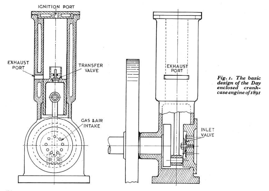 In Fielding's patent of 1881, engine construction
was simplified by using an enclosed crankcase as a
charging pump. The engine patented by Day in
1891 carried this idea still further, besides eliminating
mechanically operated valves and their operating gear.
In Fig. 1, based on Day's parent specification,
it will be seen that the charge of air/fuel
mix (carburetion and ignition details are not
shown) is taken in through a large disc valve in
the end plate and, after precompression in the
crankcase, is transferred to the cylinder through an
automatic valve in the piston crown, while the
exhaust is released through a port uncovered by the
piston. Both these events take place dining the
later part of the down stroke and the beginning
of the up stroke.
In Fielding's patent of 1881, engine construction
was simplified by using an enclosed crankcase as a
charging pump. The engine patented by Day in
1891 carried this idea still further, besides eliminating
mechanically operated valves and their operating gear.
In Fig. 1, based on Day's parent specification,
it will be seen that the charge of air/fuel
mix (carburetion and ignition details are not
shown) is taken in through a large disc valve in
the end plate and, after precompression in the
crankcase, is transferred to the cylinder through an
automatic valve in the piston crown, while the
exhaust is released through a port uncovered by the
piston. Both these events take place dining the
later part of the down stroke and the beginning
of the up stroke.
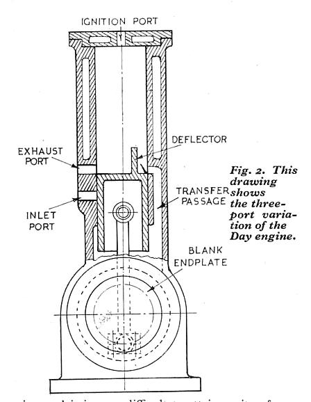 In later development by Day and some other
engineers, the automatic valves were eliminated,
and all there events controlled by the piston through
ports in the cylinder, as shown in Fig. 2.
A deflector is fitted to the piston head with the object
(only partially achieved) of directing the fresh
mixture upwards and preventing it from escaping
or mixing with the exhaust gases. In the "three-port" engine,
as it is called, the mechanical system
is reduced to the minimum of three working parts,
and this has been the pattern for the great majority
of two-stroke engines ever since. The diagrams are
explanatory only, and not complete or exact in
detail, but they are approximately correct in preportions
and design of the actual engines.
In later development by Day and some other
engineers, the automatic valves were eliminated,
and all there events controlled by the piston through
ports in the cylinder, as shown in Fig. 2.
A deflector is fitted to the piston head with the object
(only partially achieved) of directing the fresh
mixture upwards and preventing it from escaping
or mixing with the exhaust gases. In the "three-port" engine,
as it is called, the mechanical system
is reduced to the minimum of three working parts,
and this has been the pattern for the great majority
of two-stroke engines ever since. The diagrams are
explanatory only, and not complete or exact in
detail, but they are approximately correct in preportions
and design of the actual engines.
Fifty years of experimental work
 I have been personally interested in the design
of both four-stroke and two-stroke engines in small
sizes almost as long as I can remember, but the first
that I actually designed were of the latter types.
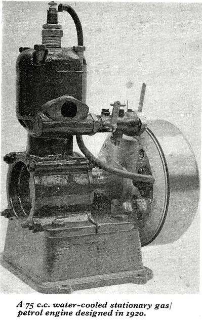
They included an air-cooled motor-cycle engine, a
three-cylinder engine for light aircraft, and a watercooled
stationary (or marine) engine, all of which
worked fairly well, but failed to achieve commercial
success for reasons unconnected with technical
merit. Most of the engines designed since that date
have been "models" in the sense that they were
intended to drive or propel models of some kind,
though it is often contended that such engines are
not models in the true sense of the term, as they do
not emulate full-size engines in scale proportion.
But this applies to nearly all miniature i.c. engines
up to the present day; though it is not absolutely
impossible to build them more or less accurately
to resemble full-size engines of certain types, it is
not generally expedient to do so, if they are required to
work as efficiently aspossible.
I have been personally interested in the design
of both four-stroke and two-stroke engines in small
sizes almost as long as I can remember, but the first
that I actually designed were of the latter types.
They included an air-cooled motor-cycle engine, a
three-cylinder engine for light aircraft, and a watercooled
stationary (or marine) engine, all of which
worked fairly well, but failed to achieve commercial
success for reasons unconnected with technical
merit. Most of the engines designed since that date
have been "models" in the sense that they were
intended to drive or propel models of some kind,
though it is often contended that such engines are
not models in the true sense of the term, as they do
not emulate full-size engines in scale proportion.
But this applies to nearly all miniature i.c. engines
up to the present day; though it is not absolutely
impossible to build them more or less accurately
to resemble full-size engines of certain types, it is
not generally expedient to do so, if they are required to
work as efficiently aspossible.
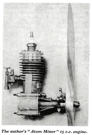 Following up the success of Capt. Bowden's
engine-powered aircraft, in demolishing records in
their class which had been held for many years, I
designed a two-stroke engine of
15 c.c. capacity in 1932, which I called the Atom Minor.
In power and reliability, demonstrated in Bowden's Blue
Dragon and other aircraft, proved beyond all doubt
that all existing records in endurance, speed and
altitude of model aircraft would become things of
the past.
Following up the success of Capt. Bowden's
engine-powered aircraft, in demolishing records in
their class which had been held for many years, I
designed a two-stroke engine of
15 c.c. capacity in 1932, which I called the Atom Minor.
In power and reliability, demonstrated in Bowden's Blue
Dragon and other aircraft, proved beyond all doubt
that all existing records in endurance, speed and
altitude of model aircraft would become things of
the past.
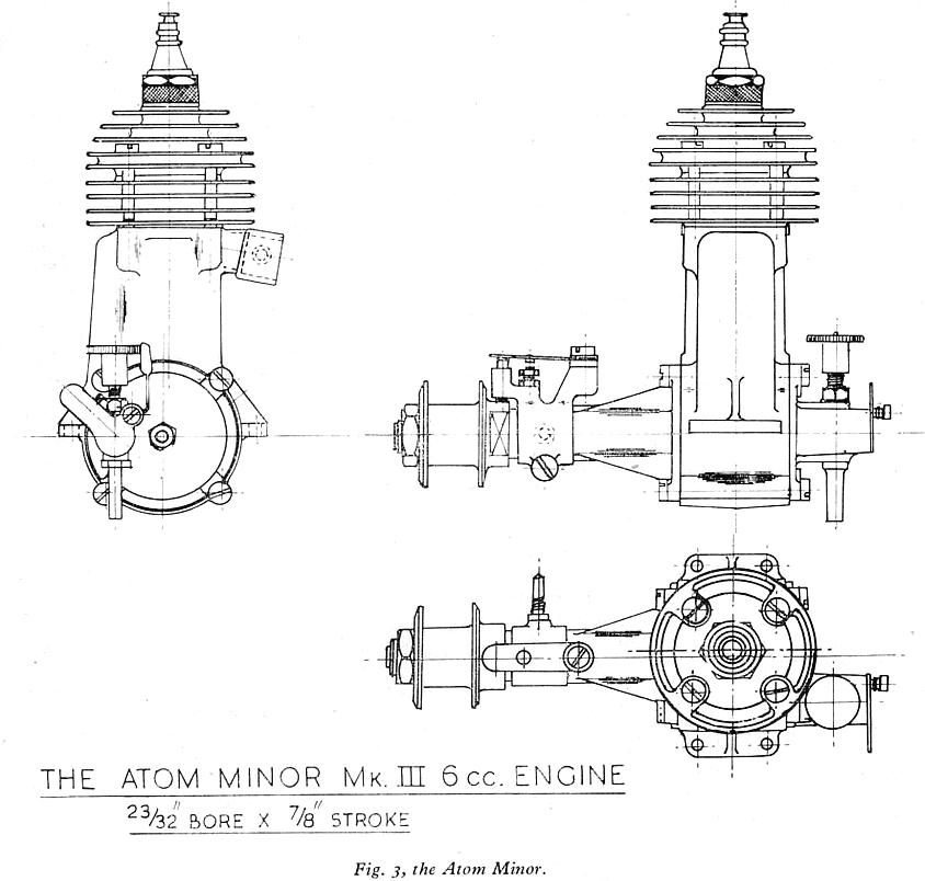 During the war, I was invited by a well-known
firm of motor-cycle engine manufacturers to submit
a simple engine design, suitable for production
in moderate quantities, for a specific purpose not
entirely unconnected with the war effort. The
engine I produced was an improved version of the
6 cc Atom Minor. It gave results which satisfied
requirements, and a number of "tool room"
prototypes were made, but I was never fully informed
what they were used for! (Official secrets and all
that, you know.) The Atom Minor Mark III has
never been described in M.E., but a handbook on
its comstruction was published after the war by
Percival Manhall & Co, and was fairly popular,
though 6 cc has since proved to be an unfashionable
size. An external view of this engine is shown
in Fig. 3
During the war, I was invited by a well-known
firm of motor-cycle engine manufacturers to submit
a simple engine design, suitable for production
in moderate quantities, for a specific purpose not
entirely unconnected with the war effort. The
engine I produced was an improved version of the
6 cc Atom Minor. It gave results which satisfied
requirements, and a number of "tool room"
prototypes were made, but I was never fully informed
what they were used for! (Official secrets and all
that, you know.) The Atom Minor Mark III has
never been described in M.E., but a handbook on
its comstruction was published after the war by
Percival Manhall & Co, and was fairly popular,
though 6 cc has since proved to be an unfashionable
size. An external view of this engine is shown
in Fig. 3
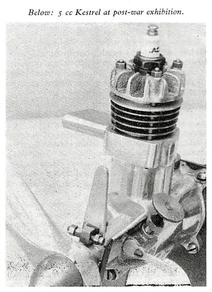 But in the chronological order of things, the Mark III
is out of its proper place, because in 1937 I produced the
5 cc Kestrel engine, which was not only successful from
the functional aspect, but also appealed to many
constructors who had not previously attempted to build
a petrol engine. It featured in several early attempts
by model engineers whose names later became well known in
connection with model cars and boats.
But in the chronological order of things, the Mark III
is out of its proper place, because in 1937 I produced the
5 cc Kestrel engine, which was not only successful from
the functional aspect, but also appealed to many
constructors who had not previously attempted to build
a petrol engine. It featured in several early attempts
by model engineers whose names later became well known in
connection with model cars and boats.
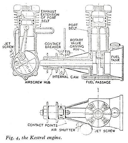 In post-war years, a 5 cc engine specially intended
for model racing cars, known as the Cadet,
was designed, together with another of 10 cc known
as the Ensign, for either cars or boats.
The early International class hydroplane engines
of 30 cc Atom II and Atom III were followed up by
Atom V, which had several unorthodox features
of design. A great interest arose in the use
of small engines for attachment to pedal cycles,
and I designed the Busy Bee, 50 cc engine which
was described in M.E. in the early 1950s
and has been built and used by many readers.
Some of these Bees, I understand, are still buzzing!
A modified version, the Bumble Bee, was designed for light
stationary work. Other post-war designs include
the Zephyr 2-1/2 cc engine, the Ladybird 2-1/2 cc
twin (C.I.) [rc: Compression Ignition, aka "diesel"]
and the Cherub 10 cc twin.
In post-war years, a 5 cc engine specially intended
for model racing cars, known as the Cadet,
was designed, together with another of 10 cc known
as the Ensign, for either cars or boats.
The early International class hydroplane engines
of 30 cc Atom II and Atom III were followed up by
Atom V, which had several unorthodox features
of design. A great interest arose in the use
of small engines for attachment to pedal cycles,
and I designed the Busy Bee, 50 cc engine which
was described in M.E. in the early 1950s
and has been built and used by many readers.
Some of these Bees, I understand, are still buzzing!
A modified version, the Bumble Bee, was designed for light
stationary work. Other post-war designs include
the Zephyr 2-1/2 cc engine, the Ladybird 2-1/2 cc
twin (C.I.) [rc: Compression Ignition, aka "diesel"]
and the Cherub 10 cc twin.
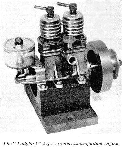 It is not my intention to bore readers with a catalogue
of engine specifications, but the above engines are, I think,
worthy of mention as examples
of experimental design. To illustrate their salient features
of design, drawings of some of them have been reproduced.
In a few details, these differ from the drawings originally
published, to incorporate minor modifications introduced
in the course of development. The word "experiment" so
frequently used in these descriptions is often loosely
applied, and may mean anything or nothing in particular
instances, but generally it indicates some attempt to
improve design in respect of functional efficiency,
power-weight ratio, or materials and methods of
construction. There is no advantage in altering design
simply for the sake of being
"different," but it is equally futile to adhere slavishly
to conventions which, for all one knows, may be based
on ancient fallacies.
It is not my intention to bore readers with a catalogue
of engine specifications, but the above engines are, I think,
worthy of mention as examples
of experimental design. To illustrate their salient features
of design, drawings of some of them have been reproduced.
In a few details, these differ from the drawings originally
published, to incorporate minor modifications introduced
in the course of development. The word "experiment" so
frequently used in these descriptions is often loosely
applied, and may mean anything or nothing in particular
instances, but generally it indicates some attempt to
improve design in respect of functional efficiency,
power-weight ratio, or materials and methods of
construction. There is no advantage in altering design
simply for the sake of being
"different," but it is equally futile to adhere slavishly
to conventions which, for all one knows, may be based
on ancient fallacies.
Cylinders
In the smaller sizes of engines (less than 10 cc for instance)
saparate cylinder castings, with flanges for ports and seatings
are liable to come out heavy and clumsy, and it is therefore
an advantage to design the cylinders so that they can be
machined all over to a fairly light section, either as a
plain sleeve or with fins on part of their length.
The former type are sometimes objected to on the grounds
that heat conduction may be imperfect, especially in
view of differential expansion of the metals employed.
But as the heat generated under working conditions
always comes from the inside, it is clear that the liner
will always be hotter than the outer part, and expansion
will look after itself, provided that excessive local
variations do not occur. In my early
engines I took great pains to machine the parts to
shrink fit limits, but later, I found this unnecessary,
and easier fits were found quite satisfactory.
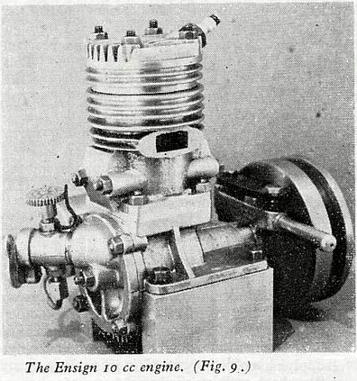 The Atom Minor Mark III had a low carbon steel liner
which, after partial machining, was carburised on the
inside surface to produce a "case" of high carbon steel.
In the Ensign engine, the daring experiment of casting in
a thin high tensile steel tube worked out successfully;
bronze, and light alloy working surfaces were also tried
with some success, but in the latter case at least,
scuffing and general roughing were liable to occur,
and one could not expect a long working life from such
cylinders. Nowadays it is possible to electro-deposit
a layer of hard chrome on light alloy cylinder walls,
but I have not been able to get this done satisfactorily
in my own engines.
The Atom Minor Mark III had a low carbon steel liner
which, after partial machining, was carburised on the
inside surface to produce a "case" of high carbon steel.
In the Ensign engine, the daring experiment of casting in
a thin high tensile steel tube worked out successfully;
bronze, and light alloy working surfaces were also tried
with some success, but in the latter case at least,
scuffing and general roughing were liable to occur,
and one could not expect a long working life from such
cylinders. Nowadays it is possible to electro-deposit
a layer of hard chrome on light alloy cylinder walls,
but I have not been able to get this done satisfactorily
in my own engines.
Port design
The size and location of exhaust, transfer and inlet ports
is one of the most critical factors in the success
and efficiency of a two-stroke engine. All engine design
involves compromise between the ideal and the practically possible, and nowhere is this more true than in the two-stroke.
The earliest engines with piston-controlled ports
were restricted in both timing and area of port opening,
as may be seem from the diagrams, Figs. 1 and 2.
These engines were not required
to run at very high speeds (500 to 600 r.p,m. was considered
very daring at the time), but when higher speed
and performance became desirable, considerably
larger ports became necessary to allow for the passage
of the gases in the very brief time permitted.
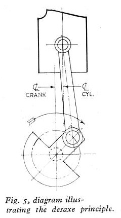 The actual period of port opening, in terms of
crank angle, is also influenced by the length of the
connecting rod in relation to the piston stroke. A
short rod has a large angle of swing, and the exhaust
and transfer ports are open for longer periods
than their height in relation to piston stroke alone
indicates. It is also possible to modify port timing
to some extent by offsetting the cylinder in relation
to the crank axis, and the same feature can be exploited
to reduce side thrust on the cylinder walls
during the firing stroke. The desaxé principle, as it
is called (Fig. 5), has been used in several of my
engines, including the Atom Minors; it appears
to be most advantageous over the lower range of
speeds, and for engines which run in only one
direction.
The actual period of port opening, in terms of
crank angle, is also influenced by the length of the
connecting rod in relation to the piston stroke. A
short rod has a large angle of swing, and the exhaust
and transfer ports are open for longer periods
than their height in relation to piston stroke alone
indicates. It is also possible to modify port timing
to some extent by offsetting the cylinder in relation
to the crank axis, and the same feature can be exploited
to reduce side thrust on the cylinder walls
during the firing stroke. The desaxé principle, as it
is called (Fig. 5), has been used in several of my
engines, including the Atom Minors; it appears
to be most advantageous over the lower range of
speeds, and for engines which run in only one
direction.
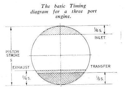 As I have many times been asked to give a suitable timing
diagram for a small three-port engine, I have showed one
[here], which may be used as the basis for
experimental work. It differs from some of the diagrams I
have given in the past, as it is based on port dimensions
in relation to piston stroke, instead of in degrees
of crank movement, which, as stated above, vary to
some extend with connecting rod length. The inlet
period is deliberately kept on the short side to
avoid blowback at low and moderate speeds and give good
acceleration under load—features which are valuable
in practice, though often neglected in engines intended
only to run at maximum speed.
As I have many times been asked to give a suitable timing
diagram for a small three-port engine, I have showed one
[here], which may be used as the basis for
experimental work. It differs from some of the diagrams I
have given in the past, as it is based on port dimensions
in relation to piston stroke, instead of in degrees
of crank movement, which, as stated above, vary to
some extend with connecting rod length. The inlet
period is deliberately kept on the short side to
avoid blowback at low and moderate speeds and give good
acceleration under load—features which are valuable
in practice, though often neglected in engines intended
only to run at maximum speed.
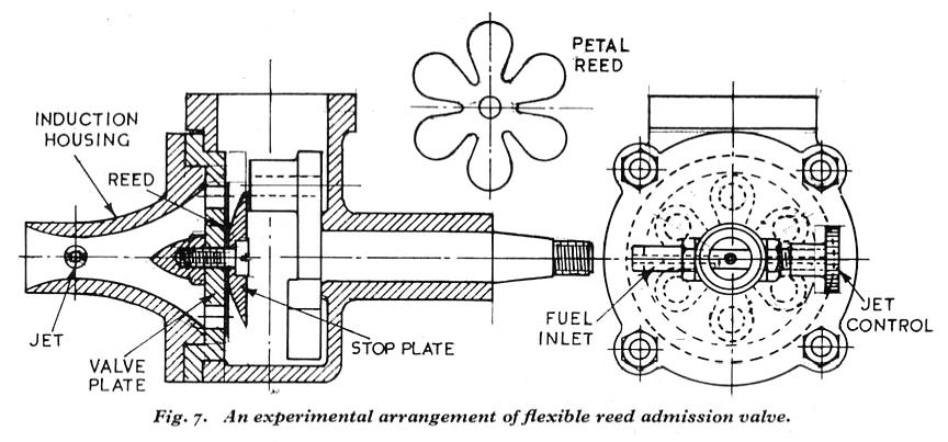 In the effort to obtain more rapid and efficient
action of automatic valves, they were often made extremely
light, in the form of discs or reeds similar to those
used in high-speed air compressors. These had somewhat
limited success, and in the case of reeds which were
required to withstand elastic deflection, failure by
fatigue was not uncommon. In recent years, interest in
reed valves has ben revived, and they have been used
successfully in some racing engines, including those by
Mr S. H. Clifford in his Poly Ester, and other hydroplanes.
The thin flexible reed generally favoured is the "petal"
type—virtually a multiple-ported valve—made of a
fatigue-resistant metal such as beryllium-copper alloy (Fig. 7.)
I was informed by
Arthur Weaver,
of the Viewing M.S.C.
some time ago that he was experimenting with a fully-floating
rigid disc "rigid" disk valve, but I do not know
what results have been obtained with it.
In the effort to obtain more rapid and efficient
action of automatic valves, they were often made extremely
light, in the form of discs or reeds similar to those
used in high-speed air compressors. These had somewhat
limited success, and in the case of reeds which were
required to withstand elastic deflection, failure by
fatigue was not uncommon. In recent years, interest in
reed valves has ben revived, and they have been used
successfully in some racing engines, including those by
Mr S. H. Clifford in his Poly Ester, and other hydroplanes.
The thin flexible reed generally favoured is the "petal"
type—virtually a multiple-ported valve—made of a
fatigue-resistant metal such as beryllium-copper alloy (Fig. 7.)
I was informed by
Arthur Weaver,
of the Viewing M.S.C.
some time ago that he was experimenting with a fully-floating
rigid disc "rigid" disk valve, but I do not know
what results have been obtained with it.
Mechanically timed admission
Many inventors have at various times made determined attempts
to improve the "breathing" of the high-speed two-stroke
engine by fitting some form of mechanically operated admission
valve to the crankcase. The types of valves include sleeve
or piston valves operated by eccentrics, and poppet
valves operated by cams, but the simplest, and generally
most satisfactory, are rotary valves of one form or another.
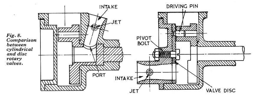 During the early days of my experimental work,
I kept up discussion (by correspondence) with enthusiasts
in many parts of the world. One of these was a young
experimenter in California named Bill Atwood, who
expressed great interest in rotary valves, and later
became the manufacturer of a well-known miniature engine
which was the first that I knew of to employ this form
of admission. It was known as the
Baby Cyclone,
and had a cylindrical valve in the crankshaft as described above.
Since then, many of the engines intended for use in
model boats, cars and aircraft have adopted similar principles,
with equal success. (Fig. 8.)
During the early days of my experimental work,
I kept up discussion (by correspondence) with enthusiasts
in many parts of the world. One of these was a young
experimenter in California named Bill Atwood, who
expressed great interest in rotary valves, and later
became the manufacturer of a well-known miniature engine
which was the first that I knew of to employ this form
of admission. It was known as the
Baby Cyclone,
and had a cylindrical valve in the crankshaft as described above.
Since then, many of the engines intended for use in
model boats, cars and aircraft have adopted similar principles,
with equal success. (Fig. 8.)
Applications of rotary valves
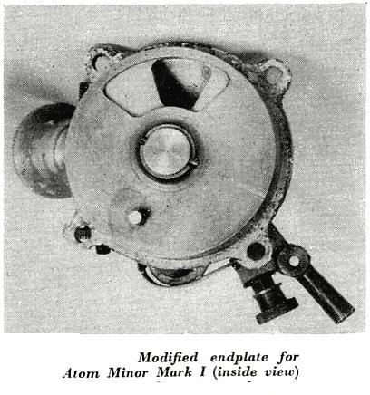 The first of my engines having a rotary admission
valve as a corporate feature of its design was
Atom II (30 cc), which was described in M.E. in 1929,
though, as already mentioned, it was the outcome
of several years' development in this and other features.
In both this and Atom III, the valve was in the form of
a cast-iron disc with a projection to engage in the end
of the crankpin, and mounted on a shaft with end-play adjuatment.
These details apply also to the later 30 cc engine,
Atom V. The Atom Minor Mark I was
designed as a 3-port engine, but when used in a boat,
a new rear endplate incorporating a rotary valve
was fitted; and the smaller engines, Mark II and III,
conceded the superiority of the rotary valve, as proved
by many tests, by eliminating the piston controlled port.
In the Kestrel 5 cc engine,
the valve was located between the
crank web and the main endplate in order to
allow the fuel reservoir to be incorporated in the
rear endplate—another innovation at the time,
though it has since become common.
The first of my engines having a rotary admission
valve as a corporate feature of its design was
Atom II (30 cc), which was described in M.E. in 1929,
though, as already mentioned, it was the outcome
of several years' development in this and other features.
In both this and Atom III, the valve was in the form of
a cast-iron disc with a projection to engage in the end
of the crankpin, and mounted on a shaft with end-play adjuatment.
These details apply also to the later 30 cc engine,
Atom V. The Atom Minor Mark I was
designed as a 3-port engine, but when used in a boat,
a new rear endplate incorporating a rotary valve
was fitted; and the smaller engines, Mark II and III,
conceded the superiority of the rotary valve, as proved
by many tests, by eliminating the piston controlled port.
In the Kestrel 5 cc engine,
the valve was located between the
crank web and the main endplate in order to
allow the fuel reservoir to be incorporated in the
rear endplate—another innovation at the time,
though it has since become common.
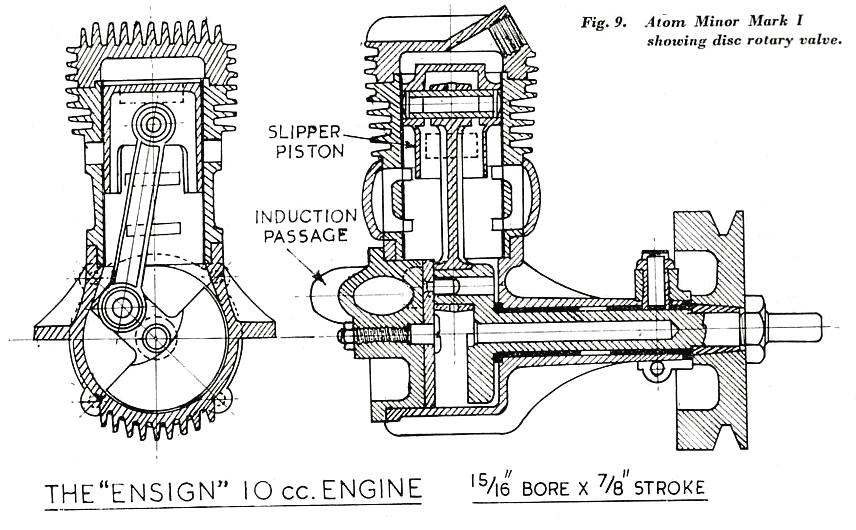 All these features can be seen in the drawings of
the vaious engines including the Ensign (Fig. 9.)
and it should not be necessary to point them out
in detail. The disc valves in the smaller engines were
were made from carbon steel gauge plate,
which, being ground on the surface, only needed to
be lapped on a glass plate to produce a true, hard
wearing seating on the light alloy endplate. They
worked best when pivoted on a stationary bolt,
rather than attached rigidly to a rotating shape. It
was, however, found that the centre hole in the disc
tended to wear oval, indicating that it was out of
balance, and the addition of extra weight in appropriate
location enabled this to be remedied. The
driving pin was flush riveted to the disc, and, provided
that any projection was carefully eliminated,
this has proved quite satisfactory.
All these features can be seen in the drawings of
the vaious engines including the Ensign (Fig. 9.)
and it should not be necessary to point them out
in detail. The disc valves in the smaller engines were
were made from carbon steel gauge plate,
which, being ground on the surface, only needed to
be lapped on a glass plate to produce a true, hard
wearing seating on the light alloy endplate. They
worked best when pivoted on a stationary bolt,
rather than attached rigidly to a rotating shape. It
was, however, found that the centre hole in the disc
tended to wear oval, indicating that it was out of
balance, and the addition of extra weight in appropriate
location enabled this to be remedied. The
driving pin was flush riveted to the disc, and, provided
that any projection was carefully eliminated,
this has proved quite satisfactory.
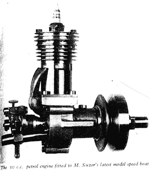 It has been mentioned that mechanical control of
exhaust or transfer port timing is liable to be
difficult and complicated; but so far as the transfer
port is concerned, this problem did not defeat the wit of the
redoubtable Gems Suzor. In his 10 cc engine,
as used in his first post-war hydroplane Mdlle.
Sylla, the rotary valve controlled both admission
and transfer ports in the crankcase.
The latter led to a forked pipe which injected
mixture into two of the open exhaust ports at
just the right moment before they closed.
This ingenious device was undoubtedly successful,
but unfortunately could not be used with a closed
exhaust pipe and silencer.
It has been mentioned that mechanical control of
exhaust or transfer port timing is liable to be
difficult and complicated; but so far as the transfer
port is concerned, this problem did not defeat the wit of the
redoubtable Gems Suzor. In his 10 cc engine,
as used in his first post-war hydroplane Mdlle.
Sylla, the rotary valve controlled both admission
and transfer ports in the crankcase.
The latter led to a forked pipe which injected
mixture into two of the open exhaust ports at
just the right moment before they closed.
This ingenious device was undoubtedly successful,
but unfortunately could not be used with a closed
exhaust pipe and silencer.
Crankcase compression
The limitation in volumetric effeciency of two-stroke
engines is primarily due to the incomplete
charging of the cylinder by using the crankcase as a
pump. Apart from the loss of effective volume
through imperfect port timing, the necessary clearance
space to accommodate working parts imposes
a limit on the pressure which can be produced in
the crankcase. Many designers have taken staps,
sometimes drastic, to reduce crankcase clearance
to the bare minimum in order to improve both
suction and pressure effects.
Piston design
It may be said that the piston of a two-stroke
engine has a fourfold function, as it must act
as a cylinder seal, a pressure transmitter,
a piston valve and a crosshead. Unlike a
four-stoke engine piston, which may be
fitted to the cylinder with a large clarance
if spring rings are used to provide the seal,
a close contact of the piston to the cylinder wall is
essential to avoid leakage at the ports.
The effect of differential expansion of the parts is therefore
pronounced in two-stroke and
where light alloy pistons are used, it is advisable to
use a low-expansion alloy, and also to design them
in such a way that heat is conducted away front the
crown as rapidly as possible. In some respects the
air flow on the underside of the piston helps to keep
it cool.
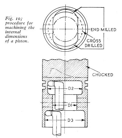 It is often necessary to make small pistons from
solid material, owing to the difficulty of
obtaining accurate castings. The main problem
involved in doing so is to machine the inside to reduce
weight as much as possible, while retaining
adequate strength. Having made many pistons in this way,
I can recommend the methods shown in Fig. 10.
The material (preferably cost-iron stick) should
first be machined parallel on the outside,
so that it can be chucked truly, and, if necessary, rechucked
for subsequent operations. After facing and centering,
it is drilled and bored to dimension D1,
and finished to required depth by a flat-ended drill or and mill.
The dimensions D2 and D3 can be bored out by a
round-nored boring tool, which may be made from
round silver steel bar and held in a split holder.
Depth measurements can be taken from the end of
the holder, and undercut diameter D2 can be measured
by means of the cross feed index. If no rings are
to be fitted, D2 can be opened out to the same
size as D3. Outside diameter can be finished at
the same setting if desired, but it is generally
better to carry it out in a later operation.
It is often necessary to make small pistons from
solid material, owing to the difficulty of
obtaining accurate castings. The main problem
involved in doing so is to machine the inside to reduce
weight as much as possible, while retaining
adequate strength. Having made many pistons in this way,
I can recommend the methods shown in Fig. 10.
The material (preferably cost-iron stick) should
first be machined parallel on the outside,
so that it can be chucked truly, and, if necessary, rechucked
for subsequent operations. After facing and centering,
it is drilled and bored to dimension D1,
and finished to required depth by a flat-ended drill or and mill.
The dimensions D2 and D3 can be bored out by a
round-nored boring tool, which may be made from
round silver steel bar and held in a split holder.
Depth measurements can be taken from the end of
the holder, and undercut diameter D2 can be measured
by means of the cross feed index. If no rings are
to be fitted, D2 can be opened out to the same
size as D3. Outside diameter can be finished at
the same setting if desired, but it is generally
better to carry it out in a later operation.
Composite pistons
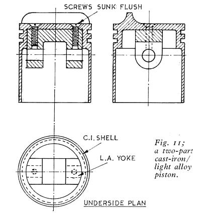 It is sometimes convenient to make the piston in
two or more parts, and perhaps [of] two different
materials. The methods which have been employed
in full-size practice are not well suited to
very small pistons, and the usual method is
to make the shell in the form of a light cup,
machined all over, and fit a yoke inside it
to carry the gudgeon pin, as shown in Fig. 11.
Sometimes the yoke is secured by a single
screw in the centre of the crown, but two screws are
to be preferred, especially
in view of the need to locate the line of the deflector
in relation to the gudgeon pin centre. It is not
desirable to allow the screw heads to project above the crown,
and if the deflector is thicker in the centre,
they may be sunk well below the surface and filled
flush with plastic metal. To prevent any risk of the
screws becoming loose, a sealant such as Loctite or
Casce ML may be applied to the threads on final
assembly, which of course must be carried out
after the gudgeon pin and connecting rod are fitted.
It is sometimes convenient to make the piston in
two or more parts, and perhaps [of] two different
materials. The methods which have been employed
in full-size practice are not well suited to
very small pistons, and the usual method is
to make the shell in the form of a light cup,
machined all over, and fit a yoke inside it
to carry the gudgeon pin, as shown in Fig. 11.
Sometimes the yoke is secured by a single
screw in the centre of the crown, but two screws are
to be preferred, especially
in view of the need to locate the line of the deflector
in relation to the gudgeon pin centre. It is not
desirable to allow the screw heads to project above the crown,
and if the deflector is thicker in the centre,
they may be sunk well below the surface and filled
flush with plastic metal. To prevent any risk of the
screws becoming loose, a sealant such as Loctite or
Casce ML may be applied to the threads on final
assembly, which of course must be carried out
after the gudgeon pin and connecting rod are fitted.
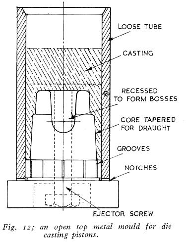 I have succeeded in making quite small pistons
accurately by a simple method of die casting,
and saveral other model engineers I know
have employed metal moulds of some form or other,
in a similar way. The core of the mould shown in Fig. 12 is
machined in steel or cast-iron integral with
or attached to a base plate, which should preferably be
made so that it can be clamped to the bench,
or in the vice. Recesses are milled in both sides to form
the gudgeon bosses, and these, together with other surfaces,
should have a draught angle of 5 to 6 deg. inclusive.
The outside of the mould is a thick-walled steel tube,
with an inside diameter giving allowance for
machining the outside of the casting.
It is registered concentrically by a spigot at the
base of the core and should be quite an easy fit.
I have succeeded in making quite small pistons
accurately by a simple method of die casting,
and saveral other model engineers I know
have employed metal moulds of some form or other,
in a similar way. The core of the mould shown in Fig. 12 is
machined in steel or cast-iron integral with
or attached to a base plate, which should preferably be
made so that it can be clamped to the bench,
or in the vice. Recesses are milled in both sides to form
the gudgeon bosses, and these, together with other surfaces,
should have a draught angle of 5 to 6 deg. inclusive.
The outside of the mould is a thick-walled steel tube,
with an inside diameter giving allowance for
machining the outside of the casting.
It is registered concentrically by a spigot at the
base of the core and should be quite an easy fit.
Deflectors
The high vertical deflectors used on the early two-stroke
engines (see Fig. 2)
performed their primary
function of directing the fresh mixture upwards,
and deterring its escape from the exhaust port, fairly well;
but they were not good heat conductors,
and often became overheated to such an extent as to cause
distortion of the piston, if the engine was hard pressed.
In later engines designed to run faster and produce more power,
it was necessary to thicken the deflector to avoid local heating,
but excess piston weight could be avoided by coring the inside
of the piston to follow the external contour. The shape of the
deflector is widely varied in different engines, and I have
often been asked "What is the ideal shape for the deflector?",
but this is another of those simple questions which are not
so simple to answer. I have tried out almost every conceivable
shape of piston crown in my experiments but have not arrived
at any definite conclusion.
The "Zephyr" 2-1/2 cc engine
This engine is illustrated not only to exemplify
some of the features discussed, but also methods of
construction in an engine made without castings.
Many constructors have built engines by fabrication
from stock materials, or machining from solid, or
a combination of both methods. While the
functional design of such engines may be more or less
satisfactory, it is not at all easy to obtain a balanced
distribution and economy of material
which is essential to really good engineering design.
It can be done—but few constructors, in my experience,
are prepared to carry out the intricate machining
operations involved in putting just the right amount
of metal in the right place, and no more.
No doubt it can be argued that it does not
matter what an engine looks like so long as it
works; but a good craftsman will always seek
to make the outward appearance of his product a
sign of its hidden inward merits.
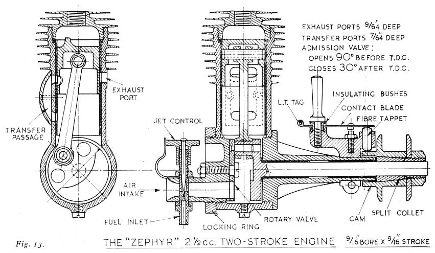 The major parts of the Zephyr (Fig. 13) were machined
from solid duralumin, which by reason of its high
tensile strength, enabled the section of metal to be
kept to the minimum without risk of weakness.
Operations on the upper part of the body were mostly
simple internal and external turning, but the lower part,
besides boring at right-angles, required shaping on
the outside by part-circular milling, planing,
and a certain amount of hand filing. The main bearing
housing was milled externally to a near-cruciform section,
to form four strengthening ribs; they could have
been dispensed with by making the circular part of
heavier section, if a little more weight was tolerated.
This applied also to the rear housing, in which a
cavity was milled around the centre boss and carburettor stub.
The major parts of the Zephyr (Fig. 13) were machined
from solid duralumin, which by reason of its high
tensile strength, enabled the section of metal to be
kept to the minimum without risk of weakness.
Operations on the upper part of the body were mostly
simple internal and external turning, but the lower part,
besides boring at right-angles, required shaping on
the outside by part-circular milling, planing,
and a certain amount of hand filing. The main bearing
housing was milled externally to a near-cruciform section,
to form four strengthening ribs; they could have
been dispensed with by making the circular part of
heavier section, if a little more weight was tolerated.
This applied also to the rear housing, in which a
cavity was milled around the centre boss and carburettor stub.
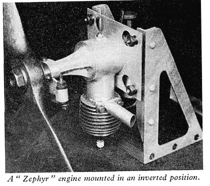 The parts were fixed together by screwing the
joints 24 t.p.i., and no screws or bolts were used
in the entire structure. A slotted locking collar
was fitted to the rear housing to enable it to be
located correctly, and this, incidentally,
allowed of adjusting the timing of the rotary valve if required.
The main bearing housing, however, was screwed firmly
home to its shoulder, and a frictionally mounted contact
breaker, similar to that of the Atom Minor, Mark III,
was fitted, and operated by a cam formed on the back
of the propeller boss.
The parts were fixed together by screwing the
joints 24 t.p.i., and no screws or bolts were used
in the entire structure. A slotted locking collar
was fitted to the rear housing to enable it to be
located correctly, and this, incidentally,
allowed of adjusting the timing of the rotary valve if required.
The main bearing housing, however, was screwed firmly
home to its shoulder, and a frictionally mounted contact
breaker, similar to that of the Atom Minor, Mark III,
was fitted, and operated by a cam formed on the back
of the propeller boss.
Piston head transfer valve
In the original Day two-stroke illustrated in
Fig. 1,
the transfer of mixture from the crankcase to the
cylinder was carried out by
means of an automatic valve in the piston head.
In some respects this might be considered a
very good arrangement, as the valve,
being operated by difference of pressure,
world open as soon as the cylinder pressure
became lower than that in the crankcase,
and remain open until the conditions were reversed.
But this ignores the effect of inertia,
which causes delay of both opening and closing,
besides possible erratic action by the location
of the valve in the moving piston,
especially at high engine speed.
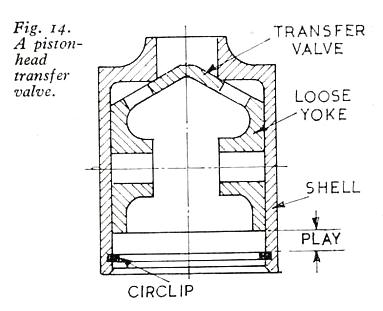 The piston head transfer valve, in various forms,
has been used in many engines in the past,
but appears to be almost completely obsolete now.
An interesting variation of the principle has,
however, been employed in recent years,
and is capable of working efficiently at very high speed.
As seen in Fig. 14, the piston comprises two parts,
one being a symmetrical outer shell, and the other,
fitted to slide freely inside it, having bosses to carry
the gudgeon pin. The innner part, or yoke, has a conical head,
which forms a valve fitting a seating in the underside
of the circular aperture of the shell.
The piston head transfer valve, in various forms,
has been used in many engines in the past,
but appears to be almost completely obsolete now.
An interesting variation of the principle has,
however, been employed in recent years,
and is capable of working efficiently at very high speed.
As seen in Fig. 14, the piston comprises two parts,
one being a symmetrical outer shell, and the other,
fitted to slide freely inside it, having bosses to carry
the gudgeon pin. The innner part, or yoke, has a conical head,
which forms a valve fitting a seating in the underside
of the circular aperture of the shell.
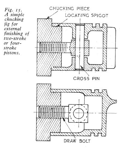 I have on more than one previous occasion described
the means I recommend for finishing the outside
diamatcr of the piston, after all other essential operations
have been caried out, It consists, as shown in Fig. 15,
of a disc of metal which may be held in the lathe chuck
or made with an internal thread to fit the mandrel nose,
having a truly concentric spigot to fit the machined
inside of the piston skirt closely, but without any
tendency to expand or spring it. The centre
disc is drilled and tapped to take an eye bolt,
or alternatively this may be made in the form
of a long draw bolt to pass right through the mandrel,
and take a draw nut on the outside. When the piston
is fitted to the spigot, a temporary, shortened
gudgeon pin is passed through the bosses and the eye
of the bolt. The piston can then be drawn firmly home
against the shoulder of the spigot far final machining,
with no risk of distortion through chuck pressure or
other causes. Measurement of clearance is facilitated,
or the cylinder may be offered up to the piston far testing the fit.
I have on more than one previous occasion described
the means I recommend for finishing the outside
diamatcr of the piston, after all other essential operations
have been caried out, It consists, as shown in Fig. 15,
of a disc of metal which may be held in the lathe chuck
or made with an internal thread to fit the mandrel nose,
having a truly concentric spigot to fit the machined
inside of the piston skirt closely, but without any
tendency to expand or spring it. The centre
disc is drilled and tapped to take an eye bolt,
or alternatively this may be made in the form
of a long draw bolt to pass right through the mandrel,
and take a draw nut on the outside. When the piston
is fitted to the spigot, a temporary, shortened
gudgeon pin is passed through the bosses and the eye
of the bolt. The piston can then be drawn firmly home
against the shoulder of the spigot far final machining,
with no risk of distortion through chuck pressure or
other causes. Measurement of clearance is facilitated,
or the cylinder may be offered up to the piston far testing the fit.
Crankshaft design
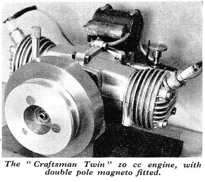 Overhung cranks are fitted to the majority of small
two-stroles, as it is generally convenient to
transmit the drive from the flywheel end, and power
take-off at the other end is not required, except for
light auxiliary drive in a few cases. There is rarely
any advantage in fitting a "full" crankshaft with
journals running in bearings at both ends, and it
may in fact complicate construction or assembly,
by necessitating a split big-end bearing, which,
however well fitted, is often a potential source
of trouble in a high speed engine. All the single
cylinder two-stroke engines from 50 cc downwards
which I have built have had overhung cranks,
with the exception of the 15 cc Pheonix, the
Busy Bee, and the Bumble Bee.
Engines with more than one
cylinder obviously call for more complicated crankshaft
construction; these include the 10 co Cadet and
Craftsman twins and the Ladybird 2-1/2 cc
(C.I.) twin. In all but the last mentioned engine, however,
the crankshafts were built up, and capable of being
disassembled, so that split big-ends were not necessary.
Overhung cranks are fitted to the majority of small
two-stroles, as it is generally convenient to
transmit the drive from the flywheel end, and power
take-off at the other end is not required, except for
light auxiliary drive in a few cases. There is rarely
any advantage in fitting a "full" crankshaft with
journals running in bearings at both ends, and it
may in fact complicate construction or assembly,
by necessitating a split big-end bearing, which,
however well fitted, is often a potential source
of trouble in a high speed engine. All the single
cylinder two-stroke engines from 50 cc downwards
which I have built have had overhung cranks,
with the exception of the 15 cc Pheonix, the
Busy Bee, and the Bumble Bee.
Engines with more than one
cylinder obviously call for more complicated crankshaft
construction; these include the 10 co Cadet and
Craftsman twins and the Ladybird 2-1/2 cc
(C.I.) twin. In all but the last mentioned engine, however,
the crankshafts were built up, and capable of being
disassembled, so that split big-ends were not necessary.
 It will be seen from the sectional drawings of typical
engines that most of the crankshafts are in one piece,
but the exceptions to this rule may be of some interest.
In the Busy Bee engine, for instance, the web and
crankpin were machined from solid, though a brazed
version was tried successfully. This was bored to
fit a taper seating on the main shaft, keyed, and
drawn up on it by a sunk head set screw.
One of the rasons for this unusual
form of construction was that in the experimental stages,
the shaft design was subject to variation,
to suit differences in the method of drive; it was
therefore regarded as the "expendable" part,
which could be changed without difficulty.
It will be seen from the sectional drawings of typical
engines that most of the crankshafts are in one piece,
but the exceptions to this rule may be of some interest.
In the Busy Bee engine, for instance, the web and
crankpin were machined from solid, though a brazed
version was tried successfully. This was bored to
fit a taper seating on the main shaft, keyed, and
drawn up on it by a sunk head set screw.
One of the rasons for this unusual
form of construction was that in the experimental stages,
the shaft design was subject to variation,
to suit differences in the method of drive; it was
therefore regarded as the "expendable" part,
which could be changed without difficulty.
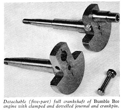 In the Bumble Bee engine, which was identical
to the former in most of its internal design,
the requirement of a double-ended shaft was
met by making it in five pieces—two journals, two webs,
and one crankpin. The parts were
made a light press fit to each other,
and further secured by partially splitting
the webs on the centre line, and fitting a high
tensile dowel bolt, the hole for which cut
into both the journal and the web, thus forming
an effective key to prevent movement of the
parts when assembled. This construction allowed
of using a hardened crankpin, while leaving
other parts soft, with less risk of distortion.
This applies also to the crankshaft of the Phoenix,
but in this case each journal and web are in one
piece, and the crankpin is a light press fit
in one web, and a lighter fit in the other,
so that it can be detached without great force.
It may be made of mild steel, brass or aluminium alloy,
and is easily renewed if necessary;
it may also serve as a spacing or oil sealing sleeve,
also to clamp a ball race if required. The taper I have found
suitable is about 10 degrees inclusive
(5 deg. on the swivelling slide) for both direct
and collet fitting. There used to be reamers
available for angles of this nature, including
the standard magneto taper, but if available
they should only be used for light finishing
of pre-machined bones.
In the Bumble Bee engine, which was identical
to the former in most of its internal design,
the requirement of a double-ended shaft was
met by making it in five pieces—two journals, two webs,
and one crankpin. The parts were
made a light press fit to each other,
and further secured by partially splitting
the webs on the centre line, and fitting a high
tensile dowel bolt, the hole for which cut
into both the journal and the web, thus forming
an effective key to prevent movement of the
parts when assembled. This construction allowed
of using a hardened crankpin, while leaving
other parts soft, with less risk of distortion.
This applies also to the crankshaft of the Phoenix,
but in this case each journal and web are in one
piece, and the crankpin is a light press fit
in one web, and a lighter fit in the other,
so that it can be detached without great force.
It may be made of mild steel, brass or aluminium alloy,
and is easily renewed if necessary;
it may also serve as a spacing or oil sealing sleeve,
also to clamp a ball race if required. The taper I have found
suitable is about 10 degrees inclusive
(5 deg. on the swivelling slide) for both direct
and collet fitting. There used to be reamers
available for angles of this nature, including
the standard magneto taper, but if available
they should only be used for light finishing
of pre-machined bones.
Bearings
There is a choice between plain (bush, sleeve or split)
bearings and rolling (ball or roller) hearings for
engine crankshafts, and it is not easy to state
definitely which is the best in all cares.
The bearing loads in two-stroke engines are
usually lower than thase in four-stokes,
and it might be expected with good lubrication,
as provided by "petroil,", almost any old kind of
bearings would give good results.
If properly made and finished, plain bushes of gunmetal
or medium bronze will work well and long in engines
of high speed and duty; phosphor bronze, so often
regarded as the ideal bearing metal, should only
be employed if the journals are hardened.
The properties of aluminium alloys, as bearing metals,
are much under-rated, and the only disadvantage of
running shafts dircutly in the crank-case
housing is that it makes renewal of worn bearings
more difficult, if it becomes necessary.
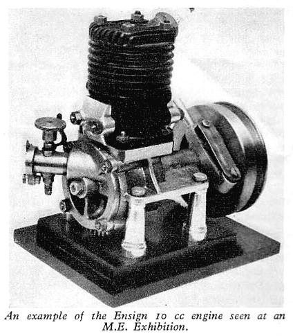 In the engine with all overhung crank, most of
the journal load comes on the ends of the bearing.
especially the inner end. It is therefore prudent
to make the bearings fairly long, or to insert
separate bushes from both ends, to give support
against the rocking effect produced by the crank.
If the total distance between the ends of the
bearing is too short, wear is liable to be more
rapid than it should be. I have generally specified
adequate effective bearing length in my engines,
as can be seen from the drawings of examples reproduced;
little is gained either in the bulk or weight
of engines in skimping the length of bearings
or their housings.
In the engine with all overhung crank, most of
the journal load comes on the ends of the bearing.
especially the inner end. It is therefore prudent
to make the bearings fairly long, or to insert
separate bushes from both ends, to give support
against the rocking effect produced by the crank.
If the total distance between the ends of the
bearing is too short, wear is liable to be more
rapid than it should be. I have generally specified
adequate effective bearing length in my engines,
as can be seen from the drawings of examples reproduced;
little is gained either in the bulk or weight
of engines in skimping the length of bearings
or their housings.
Connecting rod bearings
The crankhead or big-end bearing is undoubtedly
the heaviest loaded bearing in any engine,
and all too often it is inadequately lubricated.
With the "petroil" mixtures usually employed for
small engines, there should be no lack in the quantity
of oil applied to the bearings, but there is often
much to be desired in the mode of application.
By mixing oil with the fuel, the intention is
to bring it into contact with all working parts,
but it is obviously in a diluted from, and,
moreover, a good proportion of it fails to deposit in
the crankcase, and passes through the engine,
to be wasted ultimately through the exhaust ports.
It is therefore important to give the oil the
best feasible chance of getting where it is really needed,
that is the actual bearing surfaces of crankpins and journals.
Connecting rods
Rigidity without excessive weight is the most
essential feature of the connecting rod, which
theoretically works mainly in compression,
though, in fact, inertia and other forces
also have their effect in engines which run at high speed.
If the rod flexes sideways in action,
it upsets alignment of the bearings,
increasing friction and causing rapid wear.
In full-size practice, connecting rods are usually made from
steel forgings of I-girder section, to enable
weight to be tailored without weakness,
and bushed at the eyes, except where a rolling
bearing is fitted at the big end. It is not
usually possible to obtain forgings for the
rods of model engines, and if steel or other stock is used,
they have to be machined from solid.
For the larger size of engine,
it is worth while to mill the flutes in the rods
to something approaching the typical crosssection,
but the amount of weight which can be saved in
the smaller sizes hardly justifies this, and the
shanks of the rods are generally left in rectangular,
or occasionally, circular shape.
Flywheels
I have often been asked to give a "formula"
for the most suitable flywheel to suit an
engine of a given size, but while I am sometimes
inclined to retort "There ain't no such animal!"
it is perhaps more polite to say that it is
difficult to find a basis for calculation.
Apart from the fundamental problems of finding
the radial centre of mass, and the factor of
momentum in relation to peripheral velocity,
it would be necessary to know the friction
and back pressure involvad in carrying the
engine over its idle strokes, at the slowest
speed at which it is required to run. Speaking
for myself, I should find this a longer and
more tedious job than applying the old-fashioned
and much despised "rule of thumb" in other words,
trial and error. The flywheels in the various examples
of engines illustrated with these articles have all
been found stuitable and adequate for their purpose.
The Atom V engine
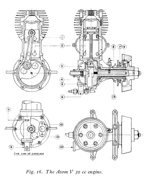 This design, illustrated in Fig. 16,
was produced as a result of experiments made
daring and after the war, and was my last attempt
at a 30 cc racing engine. The popularity of engines
in this class has
declined considerably in recent years,
as the power they are capable of developing
in a model hydroplane is almost too much for the
competitor to manage single-handed, and boats
with smaller engines have produced equal or
better results in racing events. In some respects,
the cylinder and piston design of this engine
is very unconventional, and as originally designed,
the port arrangement did not conform with popular ideas.
Several constructors of this engine made more or less
drastic detail modifications to it
(as they do to nearly all published designs).
They have a perfect right to do this, and nearly
all constructors have ideas of their own,
in these matters. So far as I am able,
I design engines to be adaptable,
and capable of minor mutations to suit
individual preference. But constauctors who
have altered the design can hardly blame the
original designer if the results obtained
do not come up to their expectations.
This design, illustrated in Fig. 16,
was produced as a result of experiments made
daring and after the war, and was my last attempt
at a 30 cc racing engine. The popularity of engines
in this class has
declined considerably in recent years,
as the power they are capable of developing
in a model hydroplane is almost too much for the
competitor to manage single-handed, and boats
with smaller engines have produced equal or
better results in racing events. In some respects,
the cylinder and piston design of this engine
is very unconventional, and as originally designed,
the port arrangement did not conform with popular ideas.
Several constructors of this engine made more or less
drastic detail modifications to it
(as they do to nearly all published designs).
They have a perfect right to do this, and nearly
all constructors have ideas of their own,
in these matters. So far as I am able,
I design engines to be adaptable,
and capable of minor mutations to suit
individual preference. But constauctors who
have altered the design can hardly blame the
original designer if the results obtained
do not come up to their expectations.
Phoenix 15 cc engine
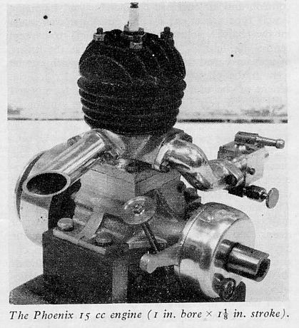 This is a straightforward "three-port" engine,
the design of which was evolved from a
self-contained generator unit of 1 in. bore x 1 in.
stroke, by increasing the stroke to 1-1/8 in.,
and making other parts to suit.
It was never intended to be a high efficiency engine,
but it worked well and reliably; several constructors
have used it in cruising boats and have been well
satisfied with its performance.
The main object of the design was to demonstrate
that a successful engine could be built by any
compotent model engineer, despite lack of experience
in this class of work. It had a three-piece crankshaft,
running in two long plain bearings,
with a pressed-in crankpin, and a simple machining
jig was employed to ensure that the assembly could
be accurately lined up. Other features of the design included
a carburettor (made without castings) which could
be adjusted to give a fair range of throttle
control, and an enclosed contact breaker,
havinf a Bosh type rocker arm.
The crankcase was made in two halves, jointed on the vertical transverse
centre-line, and an optional feature was the fitting
of a drain valve, the knurled head of which can be seen
in the photograph. This was mainly for the
benefit of the user who gets the crankcase choked
with excess petrol, so that the engine cannot be
started.
This is a straightforward "three-port" engine,
the design of which was evolved from a
self-contained generator unit of 1 in. bore x 1 in.
stroke, by increasing the stroke to 1-1/8 in.,
and making other parts to suit.
It was never intended to be a high efficiency engine,
but it worked well and reliably; several constructors
have used it in cruising boats and have been well
satisfied with its performance.
The main object of the design was to demonstrate
that a successful engine could be built by any
compotent model engineer, despite lack of experience
in this class of work. It had a three-piece crankshaft,
running in two long plain bearings,
with a pressed-in crankpin, and a simple machining
jig was employed to ensure that the assembly could
be accurately lined up. Other features of the design included
a carburettor (made without castings) which could
be adjusted to give a fair range of throttle
control, and an enclosed contact breaker,
havinf a Bosh type rocker arm.
The crankcase was made in two halves, jointed on the vertical transverse
centre-line, and an optional feature was the fitting
of a drain valve, the knurled head of which can be seen
in the photograph. This was mainly for the
benefit of the user who gets the crankcase choked
with excess petrol, so that the engine cannot be
started.
The Busy Bee 50 cc engine
In this, the largest engine to be illustrated
in the present series, the object was to assist
model engineers to construct an engine of practical utility,
which could be applied to the propulsion
of a small cycle. This idea, of course,
was as old as the hills, and it may be said
that the first motor-cycles, or most of them,
were really motor-assisted bicycles.
In the days immediately after the last war,
when mechanical transport vehicles of any kind
were difficult to obtain, a new demand arose
for small engines which could be attached to
cycles. Although a great deal of ingenuity was
devoted to their design and the methods of
driving either on the front or rear wheel,
the project was obviously doomed to
be short-lived, because they were bound to be
superseded when more efficient and comforatable
means of transport became readily available.
Nevertheless, these unpretentious little engines served a
very useful purposes for several years.
Carburation and combustion
In all i.c. engine of small capacity, carburation is
one of the most important functions, and its correct
adjustment is more essential in two-stokes than
in four-strokes. This is because in the former,
some residue of combustion gases remain in the cylinder
to mix with the fresh charge, and thereby narrows
the range of mixture strength that can by ignited.
On the other hand, the charge is very effectively
churned up, and to some extent warmed, in the
crankcase before entering the cylinder, so that it
is more homogenous, and less liable to condense
or precipitate after leaving the carburettor than
the charge supplied directly to the cylinder in a
four-stroke engine.
Combustion chamber design
It is well known that a great deal of research has
been devoted to the design of combustion chambers
of full-size engines, with the main objects of promoting
turbulence, improving the efficiency of combustion,
and reducing thermal losses. These factors become increasingly
important as the compression ratio is raised, because
the combustion space becomes more flattened or
attenuated, with a greater tendency to
combustion knocking or "pinking",
and local overheating. I do not propose
to discuss the complicated theory of combustion
head design here, as a great deal has been
written about it by designers of automobile engines,
but would point out that many of the problems involved
in these engines apply equally to models, though not
necessarily for exactly the same rasons.
For instance, pinking becomes less liable to occur
as the size of the combustion head is reduced,
and is almost non-existent in engines of 15 cc or
less per cylinder, even with very inferior or low octane fuels.
Twin two-stroke engines
Not many amateurs have attempted to build two-strokes
with more than one cylinder, and from the purely
practical aspect, it may be considered that there
is no great incentive to do so. As a means of
propelling a boat or other model, the single-cylinder
engine does all that is generally desired,
and increasing the frequency of power impulses, in
engines where they are already very high, does not
appear to compensate for the extra complication,
and possibly more tempermental performance, as the
size of individual cylinders is reduced. There is
however, a certain fascination about a twin two-stroke
(as many readers who have experience with
motor-cycles having such engines will testify) and
I have often been urged to pay more attention tp
this type. Three such engines, varying in size
and details of design, have been described in M.E.
by me, and have been successfully built by many
readers.
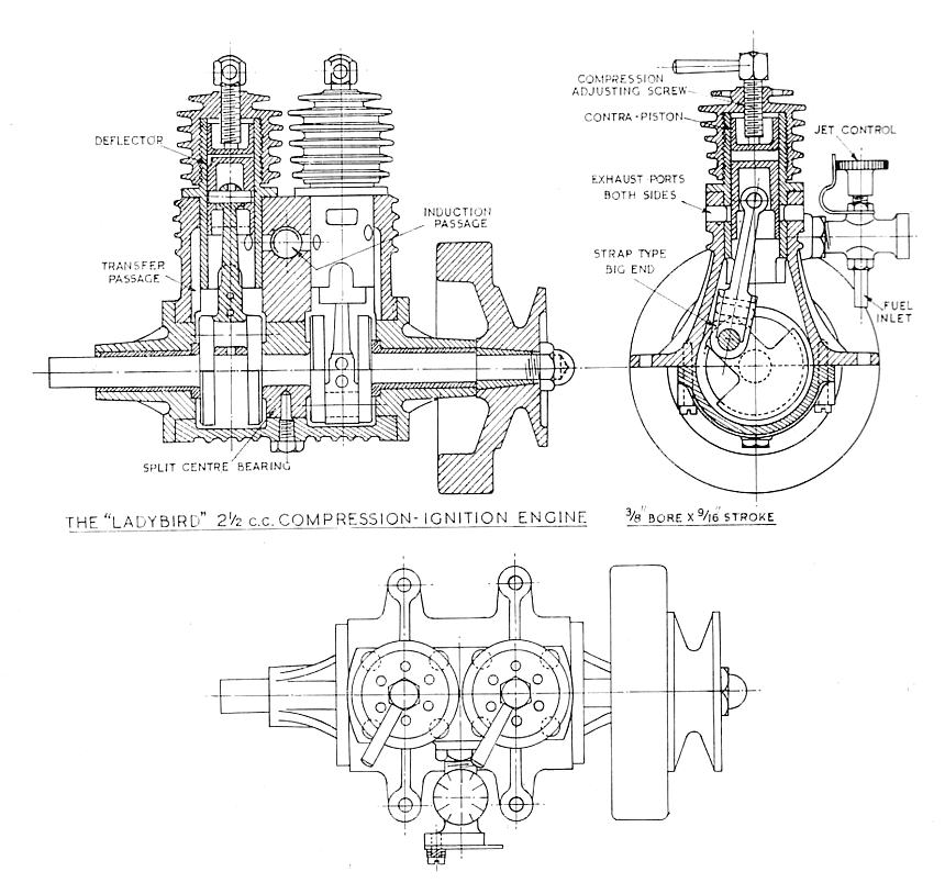 The Ladybird compression-ignition engine
(right) is one of the few exploits I have made in the
design of engines working on this principle.
Though they may appear to offer a prolific field for
development, their success depends more upon the
accuracy of construction than in the finer points of
design—and that is something one cannot put on
the blueprint. A large number of inexperienced
readers have started out to build engines from quite
sound published designs, but have partially or completely
failed to achieve success with them. In the
circumstances, I have considered that discretion is
the better part of valour, and have preferred to keep
quiet about most of my own attempts at designing them.
The Ladybird compression-ignition engine
(right) is one of the few exploits I have made in the
design of engines working on this principle.
Though they may appear to offer a prolific field for
development, their success depends more upon the
accuracy of construction than in the finer points of
design—and that is something one cannot put on
the blueprint. A large number of inexperienced
readers have started out to build engines from quite
sound published designs, but have partially or completely
failed to achieve success with them. In the
circumstances, I have considered that discretion is
the better part of valour, and have preferred to keep
quiet about most of my own attempts at designing them.
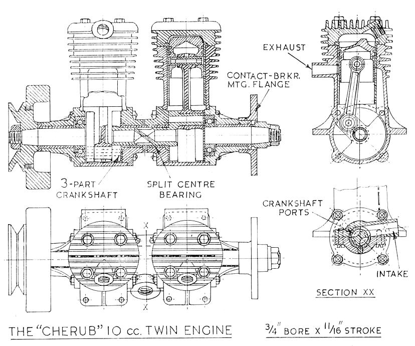 The Cherub 10 cc twin (right) employs two of
the body castings for the Cadet 5 cc engine,
with a split centre section in between them, incorporating
a cylinderical rotary valve housing and induction
passage. The crankshaft is in three piecs, the centre
one having crankpins on each end at 180 degrees to each
other, and engaging with bored seating
in the outer crank webs. To form the passages
in the centre piece of the crankshaft, it is drilled from each end
with an acute-pointed drill, leaving a blank
portion in the middle. Rectangular ports are milled
in the journal on opposite sides, each breaking
into the respective passages, and faired
into it by a riffler or rotary file. The ports are timed
to line up alternatly with a single port in the
centre bearing, to admit mixture to each crankcase in turn.
The Cherub 10 cc twin (right) employs two of
the body castings for the Cadet 5 cc engine,
with a split centre section in between them, incorporating
a cylinderical rotary valve housing and induction
passage. The crankshaft is in three piecs, the centre
one having crankpins on each end at 180 degrees to each
other, and engaging with bored seating
in the outer crank webs. To form the passages
in the centre piece of the crankshaft, it is drilled from each end
with an acute-pointed drill, leaving a blank
portion in the middle. Rectangular ports are milled
in the journal on opposite sides, each breaking
into the respective passages, and faired
into it by a riffler or rotary file. The ports are timed
to line up alternatly with a single port in the
centre bearing, to admit mixture to each crankcase in turn.
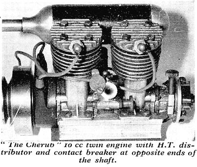 Spark-ignition in twin or multi-cylinder engines
presents certain problems. For a twin in which the
firing intervals are evenly spaced at 180 deg., one
of three systems can be used: (a) single coil,
single breaker, and h.t. distributor, (b) two
separate coils with individual breakers, or (c) special
double-pole coil and single breaker. Provision is
made in the design of the Cherub engine for fitting
any of them. The original Cherub engine had an h.t.
distributor fitted at the flywheel end, with the insulated
rotor inside the flywheel rim; but a more
accessible position for it is at the other end, mounted
on the contact breaker flange. No details of the
ignition arrangements are shown in the drawing
reproduced, but full details of alternative
components are given in the separate M.E. Plans
drawing P.E. 28.
Spark-ignition in twin or multi-cylinder engines
presents certain problems. For a twin in which the
firing intervals are evenly spaced at 180 deg., one
of three systems can be used: (a) single coil,
single breaker, and h.t. distributor, (b) two
separate coils with individual breakers, or (c) special
double-pole coil and single breaker. Provision is
made in the design of the Cherub engine for fitting
any of them. The original Cherub engine had an h.t.
distributor fitted at the flywheel end, with the insulated
rotor inside the flywheel rim; but a more
accessible position for it is at the other end, mounted
on the contact breaker flange. No details of the
ignition arrangements are shown in the drawing
reproduced, but full details of alternative
components are given in the separate M.E. Plans
drawing P.E. 28.
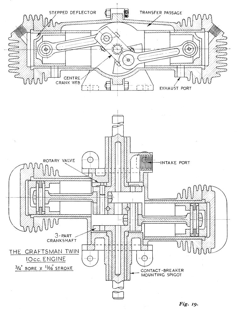 The horizontally-opposed Craftsman Twin 10 cc
engine (Fig. 19) is designed to give improved balance,
by setting the reciprocating forces against
each other. Though the offset of the cylinders produces
a slight "couple", the balance is much better
than that of a single cylinder engine at all speeds.
The cylinders fire simultaneously, so that the impulse
frequency is the same as that of a single-cylinder engine,
but is no great disadvantage at the speeds normally obtained.
A special double-pole coil as specified above (c) is
necessary for producing sparks simultaneously in both
cylinders; magnetos capable of doing so have also
been produced. Detailed drawings for this engine
are available only from Craftsmanship Models Ltd.
The horizontally-opposed Craftsman Twin 10 cc
engine (Fig. 19) is designed to give improved balance,
by setting the reciprocating forces against
each other. Though the offset of the cylinders produces
a slight "couple", the balance is much better
than that of a single cylinder engine at all speeds.
The cylinders fire simultaneously, so that the impulse
frequency is the same as that of a single-cylinder engine,
but is no great disadvantage at the speeds normally obtained.
A special double-pole coil as specified above (c) is
necessary for producing sparks simultaneously in both
cylinders; magnetos capable of doing so have also
been produced. Detailed drawings for this engine
are available only from Craftsmanship Models Ltd.
ETW's "new" and final two-stroke, the
Wombat,
an over-square 10 cc air-cooled, spark-ignition, rear-rotary valve engine.
These plans are not reproduced here.
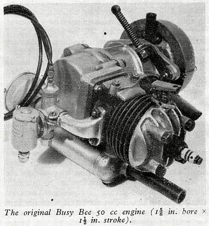
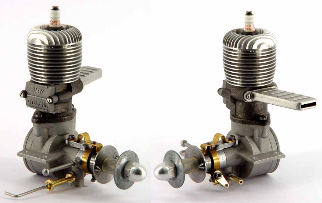
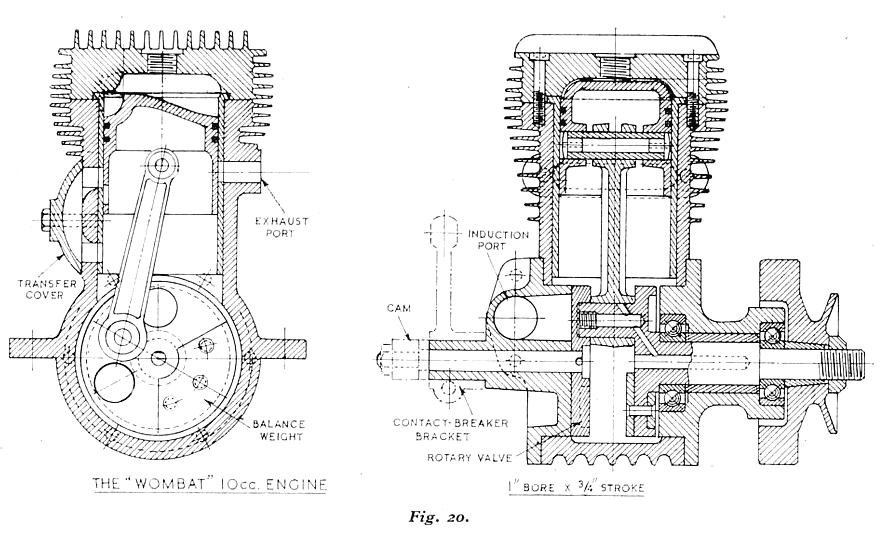