How To Measure Model Engine Performance
 Introduction
Background
Torque Measurement Techniques
Eddy-current Dynamometer
Dave Gierke Torque Reaction Dynamometer
Kirk/Washburn Water Brake Dynamometer
MEB Inertial Dynamometer
Tortora Torque and Thrust Measuring Device
Calibrated Propeller Approach
Observations
Introduction
Background
Torque Measurement Techniques
Eddy-current Dynamometer
Dave Gierke Torque Reaction Dynamometer
Kirk/Washburn Water Brake Dynamometer
MEB Inertial Dynamometer
Tortora Torque and Thrust Measuring Device
Calibrated Propeller Approach
Observations
![]()
Introduction
This is a tricky subject. With a few exceptions, it is also a subject whose secrets have been rather closely guarded by those who have made a career of it through the model press. But if the experimental process is not disclosed, what faith can we have in the results? Conversely, does it matter? If engine reviewer X uses the same technique for all his tests, a comparison of the numbers rather than the numbers themselves can be a reasonably reliable performance indication. But as pointed out by Gordon Cornell, peak torque and BHP are only part of the story; how many times do you see a figure quoted for fuel consumption?
Then there's the atmospheric conditions existing at the time of the tests to be considered. I know some engine testers of days past went to some length to obtain figures under differing atmospheric conditions which were then averaged into their final curves. Often this fact went unremarked. But how many published performance figures were the result of one test on one day due to publishing deadlines? Perhaps you start to see the problems, reminiscent of the old adage about statistics and sausages: it all depends on who made 'em, who cooked 'em, and who eats them! On this page, we'll examine the techniques available to us, and some implementations of these methods.
Background
A colorful but inaccurate phrase for a gutless engine is one that "...wouldn't pull the skin off a rice pudding...", as I should know, having made a couple like that. Power is the rate of doing work, where work is the force applied to move some object by some distance. So pulling the skin off the 'pud is work; power is how fast it can be done. If it can't be done, the engine produced zero power and the experiment should be repeated using warm milk.
James Watt coined the term horsepower as a marketing tool for his steam engines. He argued that a strong draught horse could turn a wheel 24 feet in diameter 144 times in one hour. Assuming the horse could exert a pull of 180 pounds (push actually, but let's not go there), when you multiply out the force times distance and divide by the time and you get 32,572 foot-pounds per minute. Watt rounded this up to 33,000 to be generous and gave us our empirical "horsepower". To the cynics, this also enabled him to under-specify and over-deliver.
The term brake horsepower derives from a device devised by Gaspard de Prony to determine engine torque. He wrapped a belt around the engine shaft to apply friction. The friction was increased until the shaft rotational speed was reduced. By measuring the force applied and knowing the shaft diameter and speed, the torque and brake horsepower can be calculated. Do a Google search on "watt proney" if you are curious. For example, Tom Barber investigates some Myths about Torque and Power that are worth reading.
So if we can measure the torque over a range of engine speeds, we can plot a curve of torque vs RPM, and calculate the corresponding power vs RPM values. There are a number of ways torque can be measured.
Torque Measurement Techniques
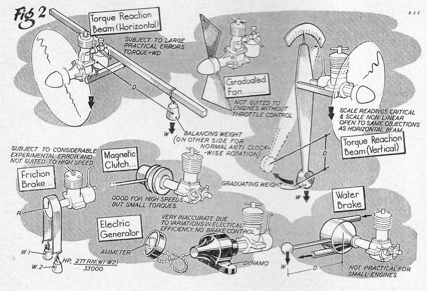 This drawing appeared in the Aeromodeller of May, 1954, and does a good job of illustrating the various means available to us for measuring the torque of a model engine. It was included in an article that described their recently introduced Eddy-current Dynamometer (noticeably absent in the illustrations) and marked a change of the guard in engine testing at Aeromodeller as Ron Warring took over from Lawerence Sparey.
Of all the methods shown, variations on the "Fan" approach are the most viable for amateur performance measurement. This is the method described in Part 9 of Gordon Cornell's Model Engine Development series. It would be a good idea to read this page now as it covers the subject quite well and will help you to understand the more esoteric approaches that follow.
The Eddy-current Dynamometer
As far as I'm aware, only Aeromodeller have employed a device like this. As noted in their May 1954 article that introduced the device, it is not suitable for testing small engines. Like all the torque measurement systems described on this page, the challenge is in calibrating the mechanism. The article below gives a basic description of the device and its construction. The following one in Question and Answer format give the effect it had on testing and the implications to the results obtained from earlier model engine reviews using less accurate methods.
 |
 |
 |
 |
 |
 |
Years ago, when electronics was my profession, I maintained an automotive eddy-current dyno for Barrie Broomhall Motors on a contra basis (Barrie tried to keep my big-noise cars running; I tried to keep his dyno running). The principal was the same, although torque was taken up by running the car's driving wheels between two steel rollers, one of which could be slowed by eddy-current braking. After calibration using a remarkable A-Frame device and some accurate weights, BHP was read direct from a large moving coil meter that measured torque reaction. The sight of a big V8 with Barrie in the driver's seat, howling at 5,000 revs in the rollers with an equivalent road speed well over 100 miles per hour, while pointed at a brick wall, was enough to send me looking for cover! But I digress...
The Dave Gierke Torque Reaction Dynamometer
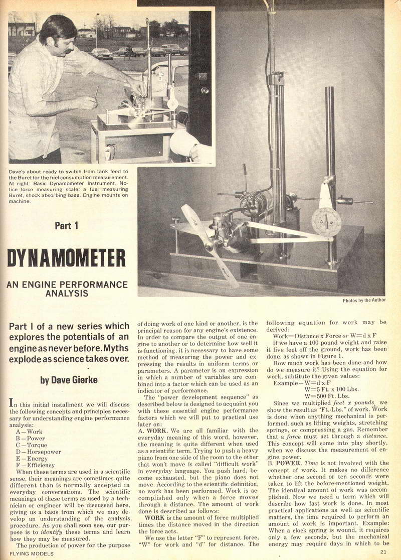
This was published as a three part series in Flying Models magazine, starting with the June 1973 issue. At the time, Dave Gierke had established his name through some very nice control line stunters, plans for which had appeared in FM. To-day, we know him as the author of two very nice books on model two-stroke engines. Dave was a technical school teacher and developed his torque-reaction dynamometer as a project in conjunction with his students. The series runs to a total of twenty-four pages, covering the construction, theory, and operation of the device. It is the most comprehensive article on model engine testing that I've ever seen, devoting considerable space to measurement and compensation for all the variables involved.
The force is measured by a spring balance positioned 10.08 inches from the axis. The reason for selecting this rather odd looking value was to simplify calculations. The BHP figure will be found by dividing the torque by 33,000 Foot-pounds per minute, but as the torque for a model engine will be best measured in ounces-inches, the constant must be multiplied by 16x12 giving 6,336,000. The torque will be Force times Distance times RPM, where the Distance is 2Π (pi) times the radius of the arm. Dave Gierke selected his arm length such that all the constants on top of the equation multiplied out to 63.36, so instead of having to remember a telephone book number as the devisor, it becomes a simple 100,000. Now all he has to do to get the BHP is multiply the Force reading in ounces by the RPM figure and shift the decimal point five places to the left.
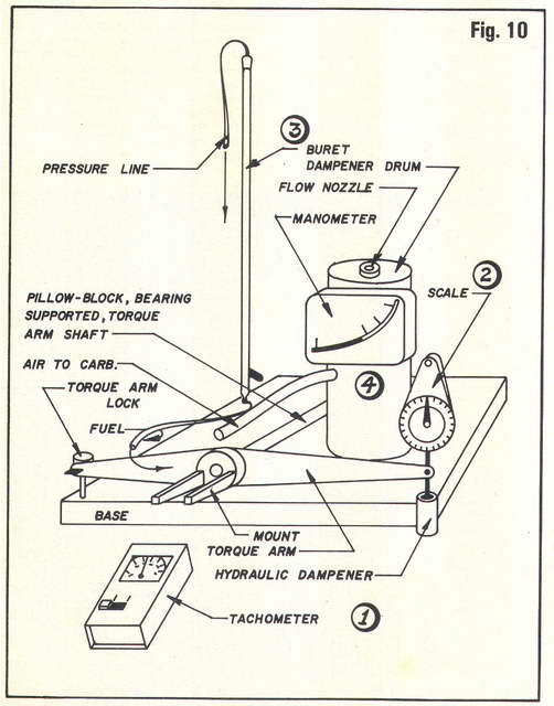
As shown by this schematic, his design is relatively simple and quite practical. It also incorporates facilities for measuring Brake Specific Consumption and does not require a lot of complicated machining, although the vibration damping dash-pot and bearing mounts would benefit from an experienced hand on the lathe. Devices of this type work better with larger engines, but still depend on a set of different props to apply different loads. The article noted that the blade finish had a measurable impact on absorption, stressing the importance of keeping the props clean and free from damage.
A variation of the torque reaction idea appears on Aerodynamics for Model Aircraft web site. Here the force by distance part of the equation is derived by placing a set of electronic scales under an arm of known length. Now I hasten to say that I've not tried this, so could be wrong, but it seems to me that as drawn, the engine vibration and non-steady nature of the un-damped device would result in a rather uncertain reading. I do completely agree with the points raised in the author's Hints and Tips though.
The Kirk/Washburn Water Brake Dynamometer
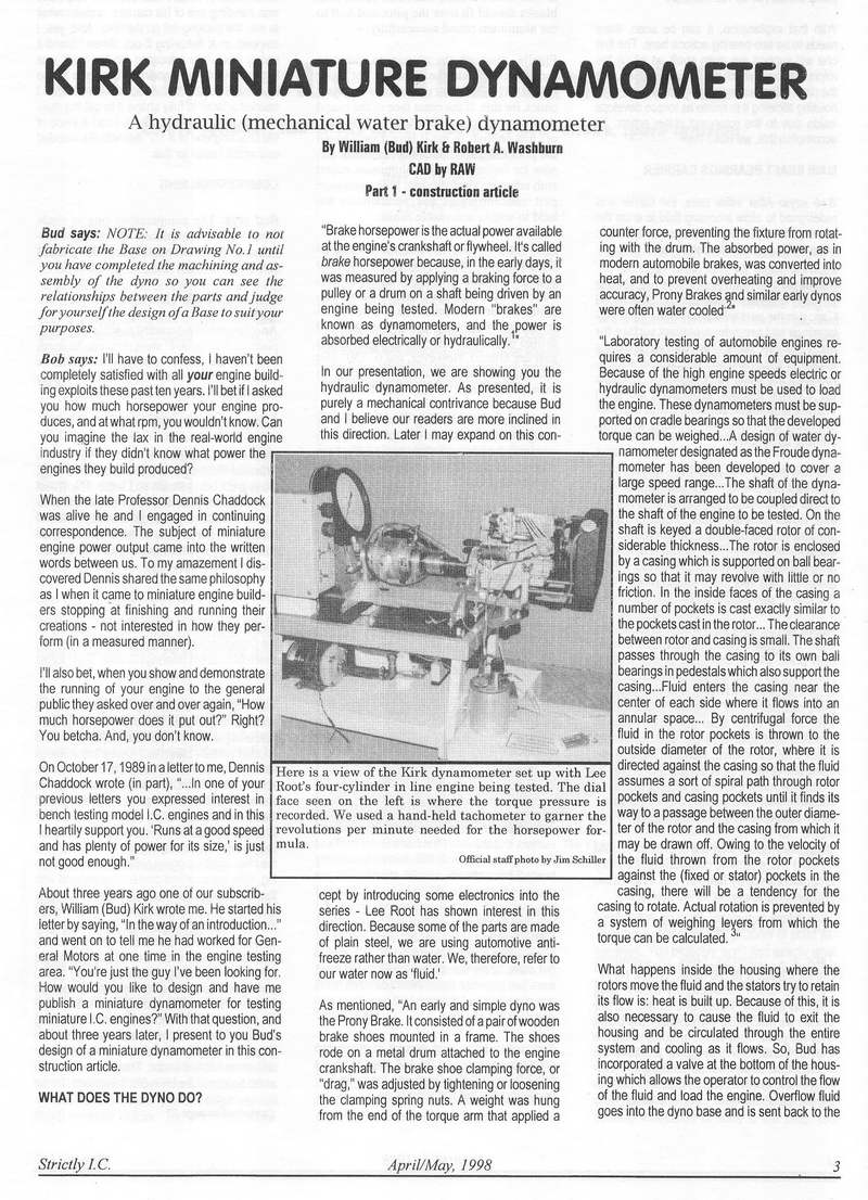 This is a very complicated device that was serialized in Strictly IC magazine in six parts, starting with Issue 62, April/May 1998. The prototype was designed and built by William "Bud" Kirk who had worked in engine testing at GM. The completed device was given to Bob Washburn who prepared the CAD drawings for it with great enthusiasm.
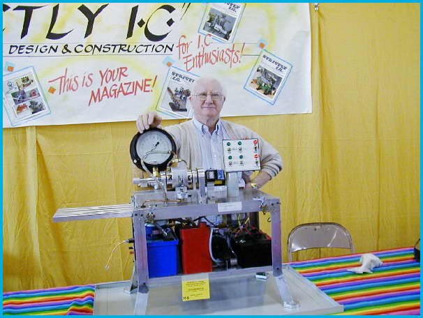
I too was enthusiastic when the series commenced, but became a bit disillusioned as the series progressed and I saw some difficulties even an experienced machinist would have constructing, calibrating, and maintaining the device. It would also be unsuitable for testing small engines and air cooled motors would rapidly over-heat. However for certain applications, it is capable of supplying highly accurate results. and although the machine is a complex device, to my knowledge, at least one has been built at the University of Idaho where it has been used in a most rigorous environment to evaluate the performance of various types of hybrid drive trains, for which it is ideally suited.
The MEB Inertial Dynamometer
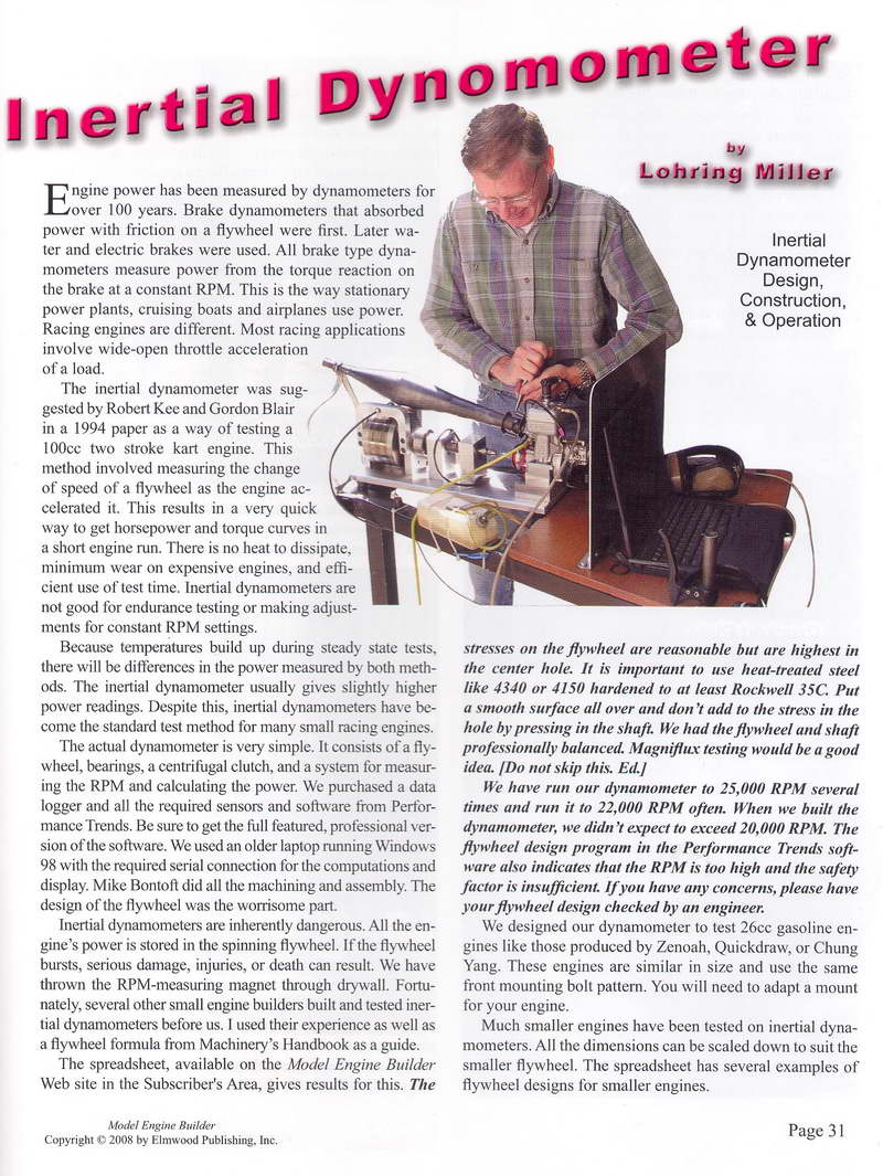
Issue #15 of Model Engine Builder has an article by Lohring Miller on the inertial dynamometer he developed to assist his racing hydroplane engine development. The engines used in this branch of the hobby are among the most powerful found anywhere, and like those used in tether cars, operate at very high RPM. The approach is based on a paper by Gordon P Blair and Robert Knee. Blair is a noted engine design academic and has authored several books on the design and simulation of two and four-stroke engines. The device uses sensors attached to a data logger to record the acceleration of a flywheel which is connected to the engine by a clutch. As noted in the article, there are potential hazards to health involved, especially when testing high powered engines, but the introduction of direct reading computer assist makes this a very flexible approach. However, as the engine under test will have no cooling airflow, nor initial load, tests will need to be kept to a short duration and no meaningful BSC measurement would be possible.
The Tortora Torque and Thrust Measuring Device
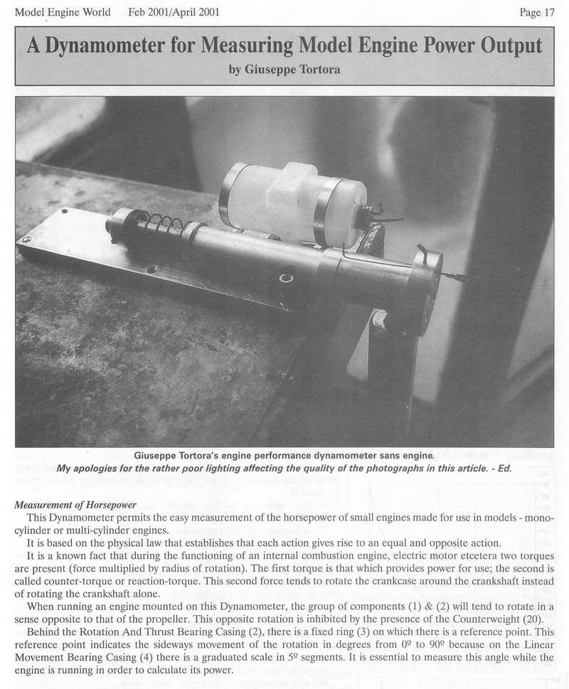
The last issue of Model Engine World edited by John Goodall was notable for a number of reasons. It carries Ken Croft's superb Delong Diesel on the cover, and contained plans for the last of Tom Crompton's EZE engine series (a horizontally opposed CO2 twin), plus construction details for a simple torque reaction device by Giuseppe Tortora. This one is considerably simpler than Dave Gierke's, but lacks a lot of the features of the latter and has no way of locking the mount during starting and tuning. With a known pendulum mass attached at a known distance from the axis, torque and power are calculated by reading the deflection of the mount in degrees and recording the engine rpm and applying a formula. Again, a series of props imposing different loads will be required if a curve is to be produced. The formula quoted in the article is:
Horsepower = Sin A * MD * RPM / 716
Where: A  is the deflection angle, and
       MD is the product of the counterweight and the
          distance from device axis to centre of mass.
The design incorporates a "spring balance" type feature that allows the thrust produced to be read directly from a calibrated scale, in whatever units you have calibrated it in. Different counterweights enable the "dyno" to be used with a range of different engine displacements. I have some reservations about this one, but it would be useful in giving some indication of the effect of a modification. Overall, I think you'd be just as well served by a set of calibrated props.
The Calibrated Propeller Approach

As mentioned earlier, the use of a set of props with known power absorption characteriscs to plot engine performance is well described in Part 9 of Gordon Cornell's Model Engine Development series. Using a set of APC props of the same brand, type, pitch and diameter as those Gordon uses will probably be close, but does leave you subject to manufacturing die differences and the possibility of different material characteristics resulting in significant variation in the power absorption characteristics.
The answer is to derive your own numbers for your own chosen props. This also permits you to trim a prop to modify its power absorption curve so as to achieve a more evenly spread set of props (see the spacing of the curves on page 25 below). When Aermodeller resumed engine testing in the 1990's, they obtained for their testers sets of specially prepared props from noted Norwegian expert, Jan David-Andersen (note the spelling error in the articles where he is named Jan David Anderson and Ian David-Anderson (I assume they really mean Jan David-Andersen, but I could be wrong).
 |
 |
An article in the Aeromodeller of April 1994 provided a little more information. Although no details of the device pictured were provided, we can make some guesses. The electric motor is fitted with stepped pullies, rather like a lathe headstock, that provide the speed ranve required—apparently up to a maximum of 20,000 rpm based on the graph. The shaft carrying the prop is carefully kept concentric with the motor shaft axis. From the complicated mounting, torque reaction seems to be being measured, though it is hard to see where, and how. I'm sure there is quite a bit more to it than that, given the number of Mystery Parts protruding from the device.
Leaving aside the precise calibration process, this way of measuring engine performance has the beauty of simplicity and given a suitable set of props, allows you to measure performance on engine from the very small, to the very large, under realistic conditions.
Observations
If anything is taken away from all this confusing discussion, it should be that the number of variables involved makes the production of accurate, repeatable, figures a complicated process. A simplified approach that provides a comparison is more easily achieved, but atmospheric conditions during the test, not to mention fuel variability may still lead to problems with repeatability.
Of the approaches examined, Dave Gierke's rig went the furthest by drawing the air through a damping system that incorporated the means to permit barometric pressure and humidity readings to be taken, thus allowing correction factors to be applied to the calculated BHP figures. For the rest of us, off-the-shelf APC props, Gordon Cornell's charts, and some common sense will probably be close enough.
![]()

This page designed to look best when using anything but IE!
Please submit all questions and comments to
[email protected]