| Unless otherwise expressed, all original text, drawings, and photographs on this page created by Gordon Cornell are licensed under a Creative Commons Attribution-Noncommercial-Share Alike 3.0 License. |

|
Model Engine Development
Part 7
-
 Break Specific Consumption
 -
Fuel Mixture Determination
-
The Jet and Mixture Control
-
Making the Jet Assembly
-
ED Super Fury MkII Spares
-
BSC Summary Table
Click on images to view larger picture.
Hover for a description.
Brake Specific Consumption
Brake Specific Consumption (BSC) is the rate of of fuel consumption divided by the power produced—effectively the fuel effenciency of an engine. This makes it a very important factor to consider in the racing environment. It is also a very difficult fugure to establish as there are many variables involved. In 1959, Ron Warring conducted a series of tests to establish a BSC figure on selected diesel and glow motors of the time. The results of which were published in the Aeromodeller. I have included a summary table of these results at the end of this page.
The shape of a BSC curve normally indicates the highest efficiency at maximum torque. This is the RPM at which Thermal and Volumetric Efficiency peak—as RPM increases the efficiency declines resulting in lower IMEP. Indirectly the torque curve also reflects the Mechanical Efficiency (ME) of the engine. Hence a plain journal bearing engine cannot match one fitted with ball bearings. In effect the BHP curve is extended when ball bearings are fitted. The most critical bearing in the engine is the crankpin, this arises because this is normally a plain journal bearing. Fitting a roller bearing could prove beneficial however this is a complex and expensive option.
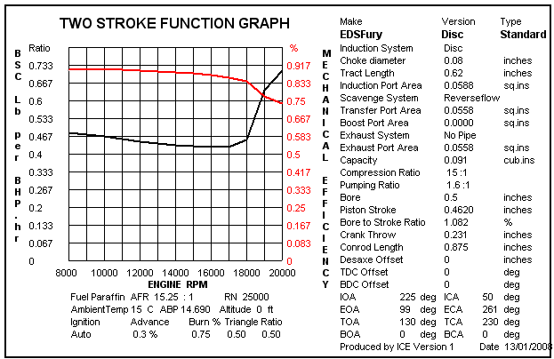
It is possible to make predictions regarding BSC and ME using the ICE program. Included here is a graph which confirms the above statement. Naturally this is based upon a pre-determined fuel to air ratio. In practice it has been established that BSC varies dramatically with mixture strength. It is important to establish the most suitable propeller and choke size in a racing environment so that the mixture strength can be optimized (the only variable being adjustment of jet flow). The required oil content in the fuel is determined primarily by the Mechanical Efficiency hence in order to improve combustion this must be minimized. Improvement to ME and combustion is where better Brake Specific Consumption may be found. The Reverse Flow porting layout of the cylinder does not appear to provide the highest feasible Scavenge Efficiency—the design being limited by the original Fury crankcase. What we are reviewing is how to achieve the best result from the existing porting, other scavenge systems can be evaluated later.
The Super Fury had quite a high fuel consumption of 15 sec/cc at 14,000 RPM using 7x6 propeller. However the power output was up to 0.25 BHP at 17,500 RPM so very high model speeds were feasible. You cannot produce high BHP if you do not consume fuel. The performance was comparable to contemporary 2.5cc engines—see chart. The highest airspeed achieved at that time was 102 mph.
Fuel Mixture Determination
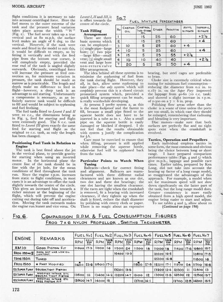
It has been established that a compression ignition engine can be made to run with excess air. The tests conducted by Ron Warring displayed a large variation in consumption at different jet settings—unfortunately no indication of the corresponding difference in RPM was recorded. The problem with our engines is the fixed choke size which in practice is only correct over a limited RPM range. To obtain the best results it is necessary to determine the most suitable size propeller, then optimize the choke diameter and jet setting to provide the desired air to fuel ratio. This will then be modified by the fuel mixture which is optimized to suit the specific engine under test. The ICE program calculates BSC based upon a fixed air to fuel ratio using a base fuel—it cannot currently apply differing mixtures. Therefore the only way to proceed currently is by practical tests. The original tests carried out at ED need to be reviewed (see the chart from Part 1 of 1/2A Team Racing which appeared in Model Aircraft, June 1962, page 172).How satisfactory a fuel is cannot be determined by the methods applied by Ron Warring. You must check RPM and consumption over the total period set by the capacity of the applied fuel tank, which in our case is 10 cc. First you warm the engine to operating temperature, then stop and refill the tank (10cc). Restart and observe RPM and any change that occurs over the period the engine runs for on a full tank. This provides greater accuracy as the elapsed time is recorded over a larger volume. Consistency is what is required; flash readings are prone to error and are difficult to repeat.
My original tests back in 1959/60 followed this practice. The problem at that time was that very little testing of fuel mixtures had been carried out. ED had for many years specified a three part equal percentage fuel. This ensured that even the worst fitted engine ran and gave a reasonable life. The situation is that it is very difficult to measure the different rates of wear and performance as mixtures are modified. Added to this, we did not fully understand the effects on performance that the ignition additives being used had.
In model engine size although the base fuel energy of Methanol and Paraffin when mixed at the correct air to fuel ratio is similar (48 ft lb per cubic inch), the compression ignition engine cannot equal the power output of the glowplug type because the mixture contains other ingredients (ether, oil etc) which change the percentage of the calorific value of the base fuel and hence, fuel energy (the correct air to fuel ratio cannot be achieved). For fuel energy see, Table 4.
| FUEL | Lower Calorific Value including Latent Heat at constant volume (BTU/lb) |
Air to Fuel Ratio by weight for complete combustion (ratio) |
Volume Ratio or specific volume after combustion / that before Combustion (ratio) |
Total Energy Released by combustion at NTP (Ftlb/in3) |
|---|---|---|---|---|
| Aromatic Free Petrol | 19200 | 15.05 | 1.053 | 48.50 |
| Petrol | 18580 | 14.30 | 1.038 | 48.15 |
| Heavy Fuels | ||||
| Heavy Aromatics | 18030 | 13.80 | 1.040 | 48.52 |
| Kerosene | 19100 | 15.00 | 1.060 | 48.91 |
| Paraffin Series | ||||
| Pentane (Normal) | 19740 | 15.25 | 1.051 | 48.70 |
| Hexane (80% pure) | 19390 | 15.20 | 1.051 | 48.35 |
| Heptane (97% pure) | 19420 | 15.10 | 1.056 | 48.64 |
| Aromatic Series | ||||
| Benzene (pure) | 17460 | 13.20 | 1.013 | 47.51 |
| Toluene (99% pure) | 17660 | 13.40 | 1.023 | 47.98 |
| Xylene (91% pure) | 17930 | 13.60 | 1.030 | 48.10 |
| Naphthene Series | ||||
| Cyclohexane (93% pure) | 18940 | 14.70 | 1.044 | 48.11 |
| Hexahydrotoluene (80%) | 18890 | 14.70 | 1.047 | 48.20 |
| Hexahydroxylene (60%) | 18890 | 14.80 | 1.054 | 48.59 |
| Olefines | ||||
| Cracked Spirit (53% unsat) | 18540 | 14.80 | 1.054 | 49.54 |
| Alcohol Group & C | ||||
| Ether (50% in Petrol) | 16830 | 13.00 | 1.060 | 49.20 |
| Ethyl Alcohol (95 vol. %) | 11130 | 8.40 | 1.065 | 46.86 |
| Methyl Alcohol | 10030 | 6.50 | 1.060 | 48.20 |
| Ethyl Alcohol (98%) | 11840 | 8.90 | 1.065 | 47.39 |
| Methylated Spirits | 10580 | 8.00 | 1.064 | 46.82 |
| Butyl Alcohol | ||||
| Carbon Disulphide (50%) | 10730 | 10.80 | 0.980 | 39.40 |
Table 4: Fuel Energy and Fuel/Air Ratio.
Note: This table of data is used to establish the Energy,
Air to Fuel Ratio etc incorporated in the FUEL database used by ICE.

To maximise output and BSC, the highest feasible percentage of base fuel must be applied. The effect of changing the percentage of the mixtures used in compression ignition engines is not as marked as with glowplug types. For example, in a glowplug engine, changing the percentage of nitro methane has a profound effect both on consumption and power output. Measurement is therefore easy to record. With a compression ignition engine, the energy content of the fuel mixture does not change so dramatically. Secondly, due to the difference in the required air to fuel ratio, the diesel engine has, in effect, approximately half the quantity of lubricant for an equal percentage of the base fuel. To explain: the required air/fuel ratio for Paraffin is 15:1 while that for Methanol is 7:1. As the fuel mixture is consumed at approximately half the rate in a diesel, the effective oil input per cycle will also be halved. In effect, 10 percent Castor in Methanol is the equivalent of 20 percent lubricating Oil in Paraffin.
Most improvements in BSC come from improving the Mechanical Efficiency (ME) of the engine, hence there is a fine balance between lubrication and fuel energy. The mixture which suits one engine may not suit another—the fact is that to optimize the fuel borders on destructive testing. The work has to be done, but it is not advisable to use your best engine for this purpose. Currently I have not seen any published data regarding the relationship between lubrication and failure.

The fuel energy will be increased by reducing the oil content. Adjusting the Isopropyl Nitrate content alters the required Compression Ratio (CR). In effect, this is similar to advancing the ignition so as RPM is increased a greater content can be beneficial. At lower RPM, excessive quantities make it difficult to set the optimum CR. Hence the two fuels indicated in Part 1 of the 1962 Model Aircraft series (ED Economic and ED Super Zip).
Although there have been significant improvements in lubricants since my original tests, Castor oil is still very widely used. The reason for this is that it carburizes (starts to burn) at some 50°C higher than mineral oil. The debate is therefore do we want the lubricant to burn, or not? The burn rate of the lubricant determines how fast the carbon deposits will build up. If we can keep crankpin bearing temperature down then we do not need Castor oil. There is not much point in un-burnt Castor exiting to exhaust. If we can burn most of the lubricant which enters the cylinder, it will release more energy.

Comma Gear Oil EP90 appears to be a satisfactory alternative lubricant to use. So far, the percentage relationship to castor oil has not been determined. Currently I am not aware of the burn rate variation relative to straight Castor oil. The lubrication additives STP and Slick 50 have been tried with no significant benefit being observed when applied with 15 to 20 percent oil already in the mixture. An improvement may be apparent at lower oil contents—just how much do you need, or is it just for running in (wearing out)? Past experience at ED with Molybdenum Disulphide destroyed a batch of engines (the ball bearings were worn out). Two-stroke mixing oil has also be tried. Normally this is used with Petrol and no perceived advantage has so far been established. The real problem here is that most modern lubricants contain additives the properties of which can change when mixed with other items in our fuel mixtures.
There does not appear to be any advantage in increasing the Ether content beyond 30 percent. Twenty-five percent should be satisfactory providing you always mix fresh fuel. Diesel mixtures degrade over time. What happens is a wax-like degradation occurs; hence the viscosity is no longer consistent. This will create an erratic flow which cannot be overcome by fitting a fuel filter.
The Jet and Mixture Control
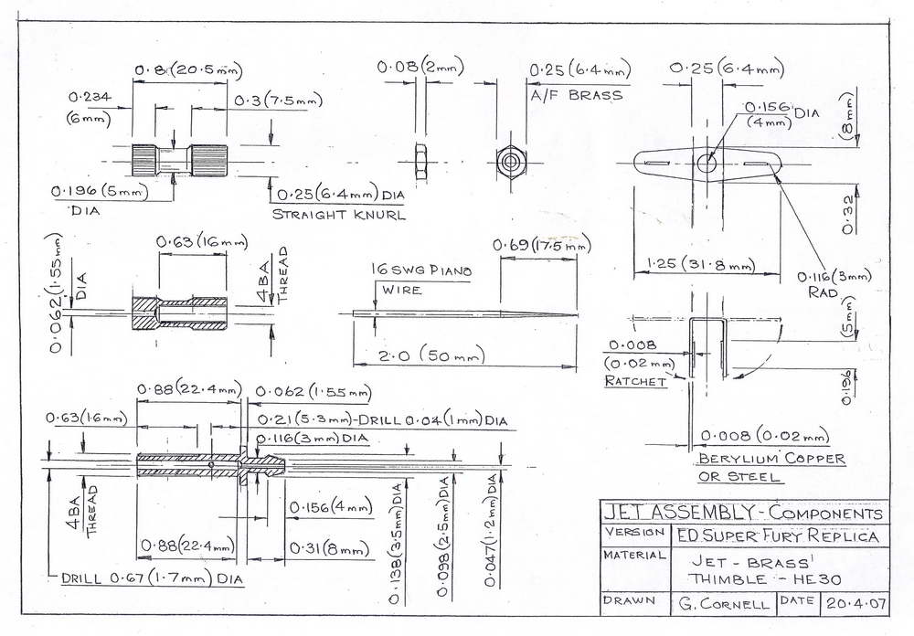
Metering of the fuel is achieved by moving a tapered needle in and out of a hole. The spray bar hole or holes, or jet, do not serve this purpose. These simply distribute the fuel in the inlet tract allowing it to mix with the air. When fitted across the inlet tract, the spray bar creates a venturi effect at the jet. Hence with this arrangement a parallel choke can be employed. To achieve fine control a relatively large diameter wire having a long, straight taper is desirable. Currently, I use 14 SWG (0.080") wire for a 4 mm spray bar. Because the engine is a replica with a 4 BA spray bar the wire specified is 16 SWG (0.064") as per the original Super Fury item.

The jet may have either one or two spray holes; the difference in performance is difficult to measure. A single hole is assembled to spray directly down the inlet tract. Depending on the length to choke diameter ratio, the fuel can enter the crankcase directly. A spray bar with two holes is assembled with these facing the choke walls. This invariably leads to fuel entering the boundary layer of the inlet tract. For a plain journal bearing engine this may be beneficial in providing lubrication as part of the induction process. A peripheral jet system functions as per the single jet and is now widely used in compression ignition engines.
Two principles are used to maintain the mixture setting—a friction lock or spring ratchet. The simplest of these is the split thimble; this may suffer from air leaks and is not completely positive. Without doubt the best system is the double spring ratchet, a feature of many commercial designs. The ratchet spring is most easily made from Beryllium Copper with no heat treatment required.

The original jet assembly fitted to the Fury received criticism because it was too coarse when operating with the reed valve. It was prone to flooding although it is possible this may have been due to installation of the fuel tank on the test rig. Because it was my intention that the engine should be up to racing standards a redesign took place. This set the standard for all future ED engines. Testing had shown that preset mixture strength was required this can only be achieved by an indexing system. The simplest way to introduce this is by a ratchet to locate the rotation of the tapered needle at a series of increments. Whilst this may not be absolutely linear it provides significant improvement over other systems. Only simple tooling is required to manufacture a ratchet spring which is subsequently made in thousands. The jet needle thimble features straight knurling to provide the index. In operation you only have to count the number of clicks to establish a setting. In a racing situation you can feel the index so it is not necessary to observe the position when making adjustments. Change in performance by practice and experience leads to improved results in competition. A frequent, common defect is thimbles that are made too short, and/or with too small a diameter. With a rear induction engine a longer device is acceptable. Bent wire extensions are not always satisfactory and can loosen the press fit of the needle in the thimble.
Making a Jet assembly
The principal difficulties in making a fuel metering device are: producing a suitable taper point, drilling small diameter holes and bending the jet end to ease fuel pipe connection. Of a secondary importance is some form of locking system is necessary to prevent engine vibration upsetting the mixture strength.
Needle points can be produced by taking a length of wire, securing the end in a vice or chuck. A tensile load is applied to the wire drawing a point till failure. Heat is applied at a suitable distance from the chuck by a bunsen burner or blow torch to reduce the required load, only red heat is necessary. This is the system used by some needle manufacturers. Turning or grinding is much more difficult. If you must, the offhand grinding is probably the easy option. Take a piece of scrap bar of approximately 1" x .25" section. Drill a running fit hole through the bar to suit the wire diameter. This is to support the wire during the grinding process. Dress the external diameter of the grinding wheel so that a flat surface is available. Clamp the wire support bar to the grinder rest at the required taper angle so that the wire can be progressively fed and the taper ground with minimal overhang. Allow sufficient wire length to handle and rotate. The wire can be allowed to rotate slowly by the cutting action. I have produced needles from piano wire and silver steel using this method.
 |
 |
Most small spray bars are made from brass. The principal reason for this is it can be machined at high speeds without cutting fluids. As a consequence greater depth holes can be produced with less risk of drill breakage. This is particularly important when automatic machines are used for manufacture. Even so, when drilling deep holes, the drill must be repeatedly withdrawn to clear the drilling chips; this is kown as "pecking". Other materials such as aluminium Alloy may be used (as per AM series of engines), however the risk of seizure and drill breakage is greater when using this material. If the thimble is also made of aluminium, then soldering to secure the needle is not feasible and a press fit is required. These engines frequently suffered from needles coming loose in the thimble (due to an inadequate press fit length). A secondary factor which exacerbated this problem was that a friction style lock was employed by a slot in the threaded portion. This slot may create an air leak making the mixture strength setting unreliable. When press fits are used to secure the needle, a longer fitted length is required.
There is no particular advantage to be gained by a small diameter needle. Metering is controlled by the taper not the diameter. Whilst some may be 18 SWG (.048"), or 16 SWG (.064") is my preferred minimum. As already stated, the diameter of wire is restricted by the thread size adopted for the spray bar. A standard reamer is not normally available, so a flat is ground on a length of the selected wire to produce a 'D bit' this is used to size/ream the needle hole and minimize air leakage.

Drilling the spray bar hole usually requires a drill jig; only a minimal length of drill should project from the chuck for this operation. As already indicated there does not appear to be a major advantage in a multiplicity of small holes. No more than two are required. One is sufficient with a larger hole reducing the risk of drill breakage. I prefer not to drill less than .030" (Number 69) and if acceptable use .039" (1mm, or Number 61).

If an elbow fuel pipe connection is required, then special bending grade brass is required. It may be feasible to bend HE30 alloy but HE9 may be more suitable. This can be achieved with very simple tooling. Take a length of round bar; and drill a central hole up it to accept the straight nozzle to be bent. Radius the hole entry in the form of a trumpet. You now have the necessary tool to bend the connector. The connector must be of sufficient length to allow for bending. A large fillet radius is required at the jet clamping face to prevent fracture and facilitate bending. If no nipple end is featured then a longer extension can be applied which is cut to length after bending. The sequence of photographs illustrates the process.
ED Super Fury MkII Spares
The jet assemblies available are to suit the Super Fury Mk II. This has a larger choke width hence the jet orifice will not be centrally spaced within the choke of the replicas as drawn. If you decide to change the choke width it may not be possible to assemble the jet and back plate fixing screws. Mixture control will be much more precise with the jet assembly made to the drawing.
BSC Summary Table
| THERMAL EFFICIENCY | ||||||||||
|---|---|---|---|---|---|---|---|---|---|---|
| Engine | Type † | Fuel | Maximum Efficiency | Maximum Power | ||||||
| RPM | BHP | Sec/cc | BSC | RPM | BHP | Sec/cc | BSC | |||
| Mills 1.3 | PB | Diesel | 6000 | 0.08 | 50.0 | 0.25 | 7000 | 0.09 | 44.0 | 0.25 |
| AM 1.5 | PB | Diesel | 11000 | 0.13 | 23.7 | 0.31 | 14000 | 0.15 | 18.3 | 0.36 |
| Elfin 1 .49 | PB | Diesel | 11000 | 0.10 | 15.0 | 0.67 | 14000 | 0.12 | 10.5 | 0.79 |
| Frog 150R | PB | Diesel | 11000 | 0.11 | 23.4 | 0.37 | 14000 | 0.13 | 18.3 | 0.42 |
| Taifun 1.5 | TBR | Diesel | 11000 | 0.14 | 19.2 | 0.37 | 14000 | 0.15 | 16.5 | 0.40 |
| Taipan 1.5 | PB | Diesel | 10000 | 0.10 | 14.6 | 0.62 | 12000 | 0.11 | 12.4 | 0.74 |
| ED 2.46 | TBR | Diesel | 8000 | 0.15 | 18.0 | 0.37 | 14000 | 0.20 | 5.5 | 0.91 |
| Enya 15D | SBR | Diesel | 10000 | 0.21 | 13.0 | 0.36 | 16000 | 0.29 | 6.3 | 0.67 |
| Frog 2.49 | TBR | Diesel | 8000 | 0.18 | 14.0 | 0.39 | 15000 | 0.25 | 7.0 | 0.57 |
| Oliver 2.5 | TBR | Diesel | 10000 | 0.26 | 12.5 | 0.30 | 14000 | 0.31 | 9.0 | 0.36 |
| PAW 2.49 | SBR | Diesel | 8000 | 0.17 | 15.0 | 0.38 | 14000 | 0.25 | 8.0 | 0.50 |
| Rivers 2.5 | TNR | Diesel | 9000 | 0.20 | 11.3 | 0.44 | 15000 | 0.27 | 5.8 | 0.63 |
| Taifun 2.5 | TBR | Diesel | 10000 | 0.21 | 13.0 | 0.36 | 13000 | 0.24 | 8.7 | 0.47 |
| Enya 15G | SBR | Glow | 12000 | 0.22 | 6.2 | 0.73 | 14000 | 0.23 | 5.4 | 0.80 |
| Fox 15G | PB | Glow | 12000 | 0.21 | 9.9 | 0.48 | 14000 | 0.21 | 8.7 | 0.54 |
| OS Max 15G | PB | Glow | 12000 | 0.22 | 7.6 | 0.60 | 14000 | 0.23 | 6.8 | 0.63 |
| AM 3.5 | PB | Diesel | 9000 | 0.23 | 8.2 | 0.53 | 11000 | 0.26 | 5.8 | 0.66 |
| DC 3.5 | PB | Diesel | 9000 | 0.25 | 7.8 | 0.51 | 12000 | 0.28 | 5.8 | 0.61 |
| ED 3.46 | SBR | Diesel | 10000 | 0.21 | 9.0 | 0.53 | 12000 | 0.22 | 7.9 | 0.58 |
| Frog 3.49 | PB | Diesel | 8000 | 0.24 | 15.0 | 0.28 | 12000 | 0.28 | 8.3 | 0.43 |
| Frog 3.49 | SBR | Diesel | 8000 | 0.24 | 18.2 | 0.22 | 12000 | 0.30 | 10.8 | 0.32 |
| Miles 3.5 | TBR | Diesel | 10000 | 0.28 | 6.2 | 0.58 | 13000 | 0.31 | 4.4 | 0.74 |
| Webra Bully 3.5 | TBR | Diesel | 9000 | 0.19 | 26.4 | 0.19 | 10000 | 0.19 | 25.0 | 0.20 |
| Eta 19G | TBR | Glow | 11000 | 0.25 | 6.4 | 0.62 | 16000 | 0.30 | 3.9 | 0.85 |
| Fox 29 | PB | Glow | 8000 | 0.30 | 8.7 | 0.38 | 14000 | 0.47 | 3.7 | 0.58 |
| Enya 29 3B | PB | Glow | 11000 | 0.54 | 3.2 | 0.58 | 14000 | 0.59 | 2.5 | 0.68 |
| Eta 29G | TBR | Glow | 13000 | 0.55 | 2.7 | 0.68 | 16000 | 0.66 | 2.0 | 0.76 |
| Glow Chief 29 | PB | Glow | 8000 | 0.33 | 8.0 | 0.38 | 15000 | 0.48 | 4.6 | 0.44 |
Table 5: Fuel Consumption.
| † | PB | plain journal bearing |
| SBR | plain journal bearing with single ballrace at the crankpin end | |
| TBR | twin/dual ballrace mounted crankshaft | |
| TNR | twin needle roller crankshaft |
There is no correlation between SWG and Piano (music) wire gauges.


This page designed to look best when using anything but IE!
Please submit all questions and comments to
[email protected]