| Unless otherwise expressed, all original text, drawings, and photographs on this page created by Gordon Cornell are licensed under a Creative Commons Attribution-Noncommercial-Share Alike 3.0 License. |

|
Model Engine Development
Part 6
-
 Crankshaft Design
 -
Crankshaft Material Selection
-
Making a Crankshaft
-
Crankshaft Balancing and the Conrod
-
Propeller Nut and Driver
-
The Crankshaft Bearings
-
Assembly and Disassembly Tools
-
Suppliers
Click on images to view larger picture.
Hover for a description.
Crankshaft Design
At the start of any engine design, the basic dimensions for the crankshaft and its bearings must be determined. These components have a marked affect on the Mechanical Efficiency, engine size, and weight. If a casting is employed for the crankcase it will be difficult to make changes later. From the manufacturing point of view, it should be as simple as feasible with no non-essential features which cannot be demonstrated to enhance performance (for example I deleted balancing from the ED Racer because it had no significant affect on performance).
 The benefit of different bore ball bearings for front and inner locations is also doubtful. Clamping of the front bearing between the propeller driver and a shoulder on the crankshaft to take the thrust load can create a trapped load between the two bearings. The outcome of this is that the inner bearing cannot be a tight fit on the crankshaft, or up against the crank web—unfortunately this is the highest loading of the two and the shaft can fret if loose. A slightly tapered crankshaft journal is a more economic solution. The front bearing does not have to be a tight fit on the crankshaft. The front end of the crankshaft journal is polished with wet and dry so that it is a sliding fit within the ball bearing - 0.0001 to 0.0002 inch reduction in diameter should be sufficient to avoid a trapped load between the two bearings. Mounting of the bearings in a steel housing to match the thermal characteristics of the crankshaft, as described in the FMV Story, is not essential.
There appears to be a slight benefit in having different size bearings for inner and outer as the the resonant RPM of each bearing will also be different. If two bearings of the same size are used, then select ball races with a different number of included balls. The race with the larger balls is fitted internally (this was found to be beneficial in the case of the ED Racer)
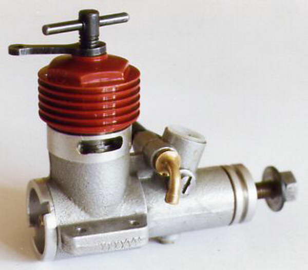
The original ED Fury crankcase limited what could be improved for the Super Fury.
Crankshaft Material Selection
The introduction of drum and/or disc induction required a modified crankshaft. The crankshaft material for ED engines at that time was EN 32 steel. Unfortunately, cyanide hardening of this was inconsistent and secondly, it was prone to machining problems, in some cases it proved to be magnetic. The shaft threads were hard so these had to be let down individually using a blow torch to avoid failures due to frontal impact. The quenching process was also prone to severe distortion creating problems in grinding the shafts to acceptable limits. A decision was made to change the material to EN 202 which is a Semi Free Cutting case hardening steel. The improvement was dramatic other manufacturers following my lead when the material specifications were published in the Super Fury test reports. This is still available from MacReadys the steel stockholder - all my current engines feature this material. These are now case hardened using the Carbo Nitride gas process with the threads kept soft. This provides a clean result with minimum distortion.
To improve the Mechanical Efficiency of the crankshaft the deflections must be reduced. Normally this cannot be achieved by a change to a higher grade steel. The reason for this is that Young's Modulus for all steels is 30 x 106. To reduce deflections you must increase the section modulus, or reduce the crankpin overhang. To minimize friction loss the crankpin must be hard because this is a plain journal bearing. Higher grade steels are more spring like and provide greater fatigue life. Changing from EN 202 to EN 36 will not result in an increase in power output—there is no super steel; EN 8 is unsuitable because it through hardens resulting in a brittle shaft.
Making a Crankshaft
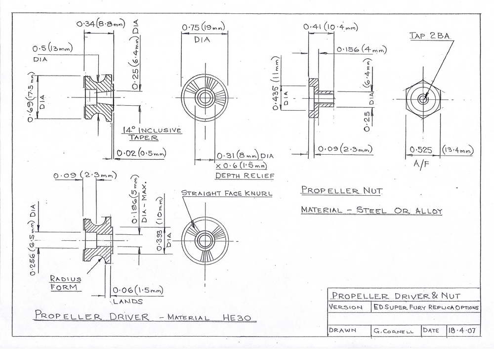
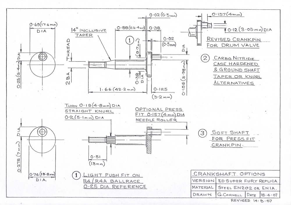 Three different shafts are required for the alternative induction systems. It is possible to have a common shaft between disc, and drum—the limitations were described in Part 3. The drawing shows these and further options which could be applied. Whilst many engines have employed a taper to secure the propeller driver this can prove difficult to manufacture to an adequate standard. It is difficult to control the distance between the driver and crank web. Because the driver requires a 2nd operation to produce the taper this can lead to production errors. The straight knurled arrangement is cheaper to produce and normally more satisfactory.


An eccentric turning fixture is used to machine the crankpin. This features a 1 mm location pin so that repeat operations and grinding of the crankpin is simplified. Although not shown on the drawing, a slot is cut through the crank web for this purpose. The fixture can take a range of shaft diameters by the application of tubular sleeves. Although not previously mentioned, this fixture may be used to drill the drive hole in the drum valve; a similar slot being required in the drive flange to achieve this.
The fit and surface finish of the crankpin is important it must also be hard to provide the required wear resistance. When first run, do not overload the engine with a large propeller. This can cause crankpin seizures. Use a 7x5 propeller and run the engine under-compressed on a rich mixture.
The option of a soft shaft with a press fit needle roller is well worth experimenting with—apply Loctite when fitting the pin. Note that a larger crank disc diameter is specified. Before running the engine check the accuracy of the crankpin by fitting a conrod, if this oscillates when the shaft is rotated it is not satisfactory and cannot be rectified.
Crankshaft Balancing and the Conrod
Ron Warring implied that the first pre-production Super Fury he tested suffered from vibration, so I created a simple test rig to evaluate this and found it very difficult to confirm. My conclusion was that he had examined the engine and thought balancing might improve it, or there had to be a fault with his propellers or test rig. Later I concluded that part of his problem was unsatisfactory fuel (Mercury no 8). I could not establish any improvement with attempts at shaft balancing so I decided to lighten the piston by reducing its length producing sub piston induction. The conrod length had to be increased to permit this leading to the production RR56 forged conrod. RPM was increased due to the reduction in reciprocating weight of the components. The crankcase could not be modified to use a shorter conrod.
My comments regarding crankshaft balancing reflect the experience at that time it does not imply that experiments regarding this will not provide an increase in power output. It is advisable to first test and evaluate the crankshaft as drawn otherwise it will not be possible to make development comparisons. The forged connecting rod has a very high strength to weight ratio—if the weight of the reciprocating components is higher than the original, then this will change the outcome.
I have examined the potential change in performance by balancing a percentage of the reciprocating mass using ICE. The change in performance predicted is shown in Table 3 below.
| % Balance | BHP | RPM | BHP | RPM | |
|---|---|---|---|---|---|
| 0 | 0.245 | 12,000 | 0.286 | 17,500 | |
| 33 | 0.245 | 12,000 | 0.286 | 17,500 | |
| 60 | 0.245 | 12,000 | 0.286 | 17,500 |
Table 3: ICE Balance Predictions.
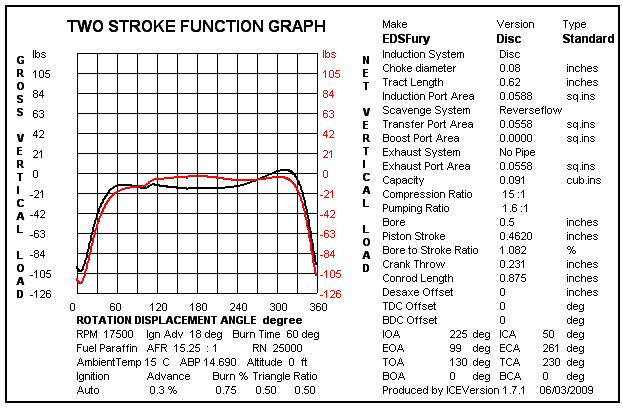 These BHP figures are slightly higher than earlier predictions due to different test settings. However it does indicate why it can be difficult to determine if there is any significant increase in BHP at the piston speeds involved. The graph showing the difference in vertical loadings is for the highest balance factor of 60% which is very difficult to achieve in a small capacity engine. The Ice program does not calculate any change due to gas turbulence or pumping ratio. This indicates the importance of minimizing the reciprocating mass as found in my tests back in 1959. What could prove beneficial is to balance the weight of the crankpin only so that the shaft is balanced (this may improve the life of the crankshaft bearings).
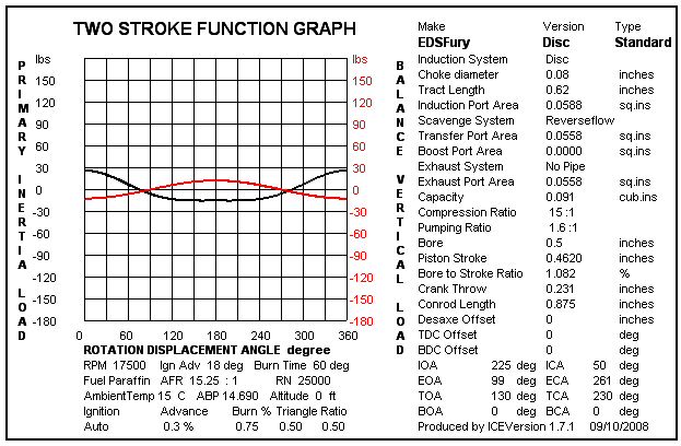
 My Dynamic 061D has this level of balance and runs up to 28,000 RPM without problems with regard to vibration. The effect of the balance compensation can be observed by the difference between the Primary and Balance mass curves. The basic problem is that additional lateral loads are created in proportion to the balance mass, hence there is little difference in average bearing load during rotation.
What should be observed when drawing comparisons with full size practice is the difference in piston speed. Vibration on a 500cc motor cycle at 6,000 RPM is quite marked, this equates to a mean piston speed of 40,000 ft/min (66ft/sec). A model engine such as the Super Fury only reaches 1,232 ft/min (20.5 ft/sec) at 16,000 RPM.
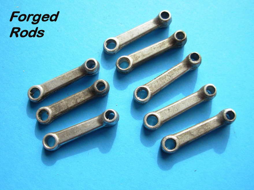
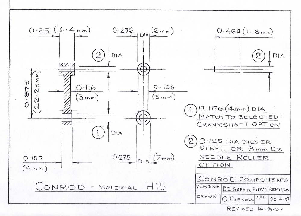
If you have vibration problems look elsewhere: unsatisfactory mounts, faulty bearings etc. Whilst many connecting rods have been fitted with a bronze bush, this can be a potential disaster. The problem with the application of a bronze bush for the connecting rod big end is associated with retaining this. The thin wall (.010") nature of this does not help matters, accuracy being doubtful during manufacture and assembly. At certain critical speeds Brinelling can take place as the bush hammers out from the rod and either rotates in the housing or seizes on the crankpin. Aluminium alloys, particularly the forging grades such as RR56, do not require a bush; consequently greater eye strength is possible reducing the hoop stress. The superior heat dissipation properties of the alloy permit these to perform satisfactorily at speeds in excess of 30,000 RPM. H15, although not as strong as RR56, gives satisfactory results for most applications.
 |
 |
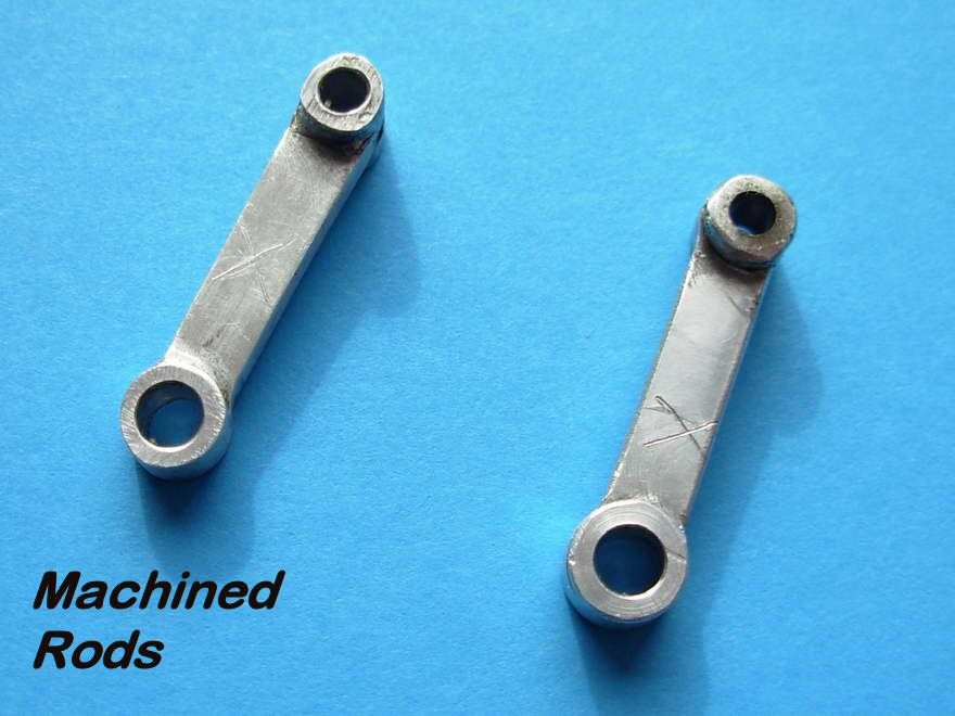 |
Original forged connecting rods are available as spares these will have a higher strength to weight ratio—several will be required for this project so you may wish to produce your own assuming you are just interested in the development process. These are best made using the ladder rail method.
 |
 |
This system can be dramatically improved when a milling machine is available. In this case the blanks are produced from larger section bar stock which enables a reduction in the number of drilling and reaming operations. Experience shows that up to 3 blanks can be processed by the depth that is set, it also gives greater accuracy. Having completed this operation a series of rails are produced by application of a slitting saw. Individual blanks are the cut from these rails. When CNC is available a rotary table is not used for profiling purposes, however the profiling fixture illustrated can be fitted to the rotary table should manual machining be required. Unfortunately manual machining usually requires a series of set ups to complete the profiling operations. Warning—Do not attempt to profile manually by hand feed as this is dangerous and may lead to injury.
The Propeller Nut and Driver
 |
 |
 |
Flight testing exposed additional problems with the spinner and propeller driver of the Fury. If a wood propeller broke, it could jam on the driver. In a racing environment, using a rod to tighten or release the spinner nut has been found to be difficult and slow. A ball handled box spanner is much quicker to apply—simply press on and turn. The special prop nut is made a firm fit inside the propeller hub, hence automatic extraction of the prop occurs as the nut is undone. Each racing propeller is fitted with its own individual nut making changes easier and faster.
Current racing rules will probably require a safety nut to be fitted; this would differ from the original as drawn with a distinct dome added to the forward face. In these circumstances, it is better to make the nut from aluminium alloy.
The Crankshaft Bearings
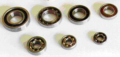
The two crankshaft bearings have different external diameters. The inner bearing is R4A, the outer is R4. These Imperial R series ball bearings are superior to the lighter metric items. A fully sealed bearing should never be fitted as these are not suitable for the RPM involved. The outer R4 bearing is frequently supplied with shields fitted to prevent the ingress of foreign matter. At least one of these should be removed. Some bearings are pre-packed with grease. All bearings should be cleaned and lubricated with 3 in 1 oil (sewing machine oil) prior to assembly. Do not rely on the manufacturer for this and never subject ball bearings to ultrasonic cleaning.
The fit of shaft to bearings and crankcase is a crucial factor affecting engine performance. The ball bearings must have adequate radial clearance, originally what were known as "2 dot" bearings had been fitted. These were replaced by R4 and R4A bearings having a 3 dot clearance; an immediate improvement was observed. It is important to appreciate that the quality of a bearing is not determined by the radial clearance.
As engine RPM is increased, the ball bearing cage is normally the limiting feature. Plastic type cages permit higher RPM operation. Metal particles from the cage can damage other engine components. However if you use plastic cage ball bearings, be aware that heating the crankcase to assemble or remove the bearings may damage the cage. Your local supplier such as SMB may be able to supply this type if other users are taking this size of bearing in quantity. The type has suffix TH added to the number.
Assembly and Disassembly Tools
 In order to ensure correct assembly of the crankshaft, bearings and propeller driver, a set of press tools are recommended. The ones used are shown in the illustration.
To disassemble, two additional pins are required. Start by pressing out the crankshaft. In some circumstances the inner ball bearing will be extracted by the crankshaft. If this is the case, then a pin 0.251 inch diameter can be used to press out the front ball bearing (the crankshaft clearance hole is the same size).
If the inner bearing remains in place then a second pin is required. This must be a loose fit in the inner bearing. First press out the front bearing by angling the tool slightly through the rear bearing. The inner bearing is then pressed out using the 0.251 inch diameter pin.
Take care reusing the ball bearings—these are so inexpensive it is hardly worthwhile.
In order to ensure correct assembly of the crankshaft, bearings and propeller driver, a set of press tools are recommended. The ones used are shown in the illustration.
To disassemble, two additional pins are required. Start by pressing out the crankshaft. In some circumstances the inner ball bearing will be extracted by the crankshaft. If this is the case, then a pin 0.251 inch diameter can be used to press out the front ball bearing (the crankshaft clearance hole is the same size).
If the inner bearing remains in place then a second pin is required. This must be a loose fit in the inner bearing. First press out the front bearing by angling the tool slightly through the rear bearing. The inner bearing is then pressed out using the 0.251 inch diameter pin.
Take care reusing the ball bearings—these are so inexpensive it is hardly worthwhile.
Suppliers
WestonUK Spares: The 1970 type crankshaft available from WestonUK Spares is made from EN 1A with only the crankpin being induction hardened. There is a short knurl at the larger end of the propeller drive taper to overcome a mismatch of the tapers. The shaft may not be sufficiently tight in the ball bearings to prevent end float. A shim will be required to prevent the crankpin damaging the disc. The forged connecting rods from WestonUK are excellent and will be a must have item for most constructors.
Ball Bearings: In the UK, suitable ball races can be obtained from:
	SMB Bearings Ltd
	Unit 8 West Oxon Ind Park,
	Brize Norton,
	Oxon OX18 3YJ
	Telephone 01993 842555
ED Spares: Email [email protected].
All major items have now been appraised, so in next part, a review of the carburettion and the jet assembly will be made.


This page designed to look best when using anything but IE!
Please submit all questions and comments to
[email protected]