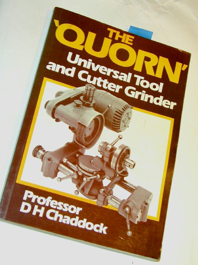
Drill Sharpening On The Quorn
Click on images to view them in larger size and more detail.
 People who complete Quorns are either (a) dedicated Model Engineers wanting the ability to sharpen all their cutters with precision, who are not afraid of complex projects, or (b) some kind of complete loon who are not afraid of complex projects. In the vain hope that I might qualify under the first category, I'd envisaged my Quorn as being the complete solution to every cutting edge in the 'shop, including twist drills. Professor Chaddock's Quorn book (reprinting and collecting the original Model Engineer articles) shows how to use the Quorn to sharpen drills using the "4 Facet Method" †. Having read this, I said to myself, fine—when I have to, I can. When I finally had to, some practical difficulties arose. In this article, I'll explore the problems and present some solutions.
First, we probably should define just what "4 facet" sharpening is, and how it differs from conventional "conical back-off" sharpening. In order to cut, a twist drill, like any tool, requires a relief behind the cutting edge. This prevents the area of the drill behind the cutting lip from rubbing on the end of the hole as it turns and advances. But we also want a strong, long lasting cutting edge, so excessive relief will make the edge more acute, and hence more susceptible to wear and damage. Let's consider the "standard" drill sharpening method first.
Conical Back-Off
 Standard conical sharpening produces a point angle of 118 degrees, but it's not a cone. The actual tip is a straight line when viewed end-on, and an arc when viewed from the side. This is called the "chisel edge" (ref [WSP12]). This is an artifact of the sharpening process and is formed by the intersection of two conical sections. This achieves what we are after: a strong cutting edge (called the "lip"), with a "land"—the area behind the lip—that falls away at an increasing rate to provide the lip relief angle necessary if the drill is to cut. Jigs to produce this shape are straight forward (relatively
  ) and a good one will produce a good result quickly—just the ticket if you are a drill manufacturer, or a user how just wants a hole and does not particularly care if it's a bit oversize, and may not be totally straight. The downside is that chisel tip. Unless the work carries a center-pop mark that is at least as wide as the chisel, the drill tip is going to wander all over the place when presented to the work. And if it starts crooked, you can be sure it's not going to get any better. This is why we generally drill a pilot with a "center" or "Slocumbe" drill (as they as called in England and her former colonies). This provides a cavity to clear the chisel point so that by the time the chisel actually reaches metal, a hole has been formed to guide the drill and there's some kind of chance it will stay on track.
Four Facet Sharpening
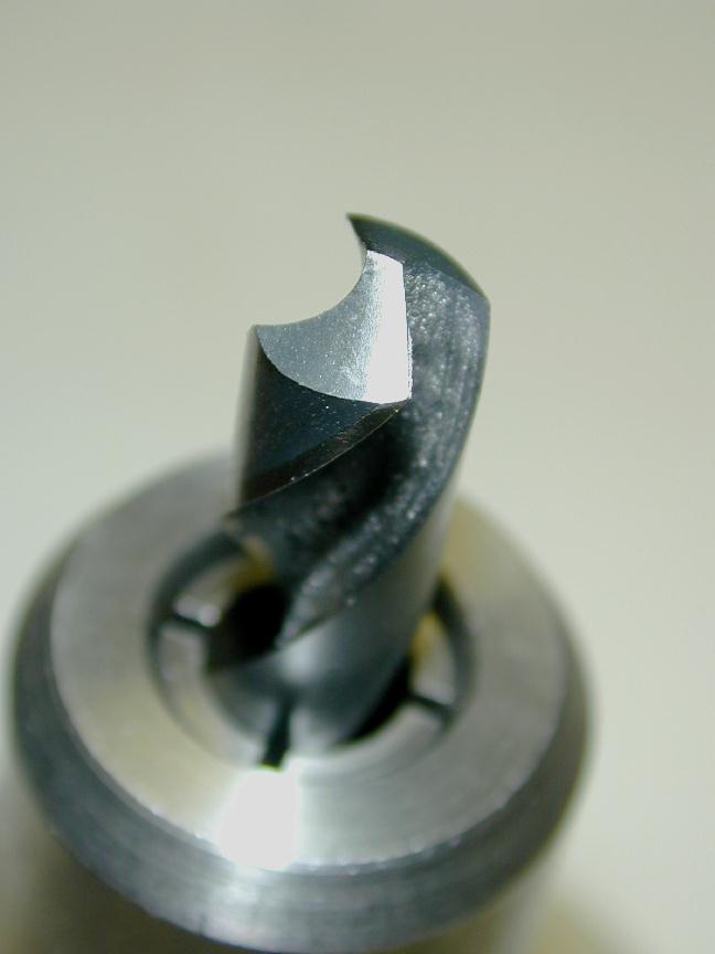
 The 4 Facet point, as seen here, is formed by grinding two flat areas (facets) on each land. The first is shallow; 80 degrees relative to the drill axis, representing a relief of 10 degrees from the plane of the drill tip. Behind this is ground a secondary relief of 25 to 30 degrees. The important part (and why you will not produce this kind of tip, hand held against the bench grinder in a hurry) is that all 4 facets MUST intersect at a single point. However, given a Quorn and some accurate, concentric way of holding the drill in the precise axis of the Toolholder Bracket, the Quorn will produce this tip perfectly with very little effort. The steps are:
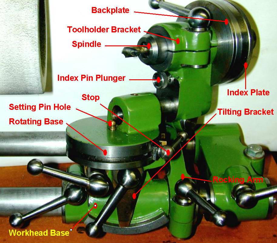
- Position the Toolholder Bracket vertical with respect to the Rotating Base using the Quorn "setting pins" as described in The Book. Note: The Quorn component names used here follow Prof Chaddock's nomenclature and the annotated photo at the top of this page will help if you are unfamiliar with the beast itself. You might like to open that photo in a separate window as you are reading this text for quick reference.
- Clamp up the drill in a collet with minimum overhang such that the line formed by the cutting lips is parallel to the plane of the Rotating Base. In practice, about 1/2" or more is needed, depending on the drill diameter and collet type to prevent any danger of the wheel grinding away collet, head, or base!
- Ensure the wheel face is set perpendicular to the bar beds and rotate the base 31 degrees so the drill point is towards you. The drill axis will now be at 59 degrees to the wheel face, and so we'll get the 118 degree point angle required.
- Incline the Tilting Bracket indicator 10 degrees to the right and lock the Workhead Base to the front bar.
- Start-up and put on cut with the Micrometer, rocking the head across the wheel until the lip cleans up over the whole existing chisel width. Note the micrometer reading, or zero it at this point.
- Index the spindle through 180 degrees (I'm assuming you engaged and locked the Index Plate at zero using the Index Pin Plunger in step 2). Back off the micrometer, and grind again to the first micrometer reading.
- Increase the tilt of the Tilting Bracket to 25 (or 30) degrees and repeat steps 5 and 6. But this time, you need grind until the two relief intersections form a perfectly straight line across the drill tip. This will be exactly on the axis of the drill, provided:
- The drill is perfectly centered in the axis of the tool holder, and
- Rotating the tool holder does not produce any axial movement of the drill, or
- The drill has not moved backwards axially in the collet
Some early experiments using Myford collets in the Myford profile Quorn spindle had produced both encouragement and disappointment. First, drills sharpened this way do start easier into the work, do cut closer to theoretical size, and do seem to cut with less pressure required. The down-side was holding the drills. Myford collets are closed by being pushed into a #2 Morse taper. Hence, they will only clamp on the work at the tip of the collet—the rear of the material will be unsupported. The more the collet has to be closed to grip the work, the more possible it is for the drill to be deflected from the perfect axial location when grinding. Second, locating the precise point to stop grinding the second and third facets is difficult. In use, the Myford spindle is captive in the Quorn work-head when the index plate is locked up (as it has to be for indexing). Grinding becomes a matter of:
- Guess where to stop on facet three by Mk I eye-ball. Note the micrometer setting.
- Index 180 degrees and grind to the same setting. Stop the wheel, rock the workhead forward, bend down and crane head into line with the drill and see of the facet intersections intersect correctly (you'd be lucky!)
- Startup again and put on another thou of cut on both faces. Repeat until perfection is achieved. If you "go over", you need to change back to the 10 degree facets and try to correct.
All in all, it's a bit labor intensive and iffy. The results are good, but because of the drama involved, sharpening is likely to be put off until really necessary—or a bit past really necessary. There's got to be a better answer.
Six Facet Sharpening
 And there is! An article by Derek Brown appeared in Model Engineer issue #4025 describing some additional jigs for the Quorn to facilitate "6 facet" sharpening. This process extends the 4 facet process, adding another secondary relief (ternary relief?) at 45 degrees, again arranged so all intersection planes meet precisely at the drill axis. The article noted that this method is now favored for CNC work as cutting force is further reduced. As the jigs required were straight forward, and as I had most of the material required in the scrap rack, AND the state of the drills in my stand were becoming a considerable embarrassment, it appeared that the time was right to address the drill sharpening problem more positively.
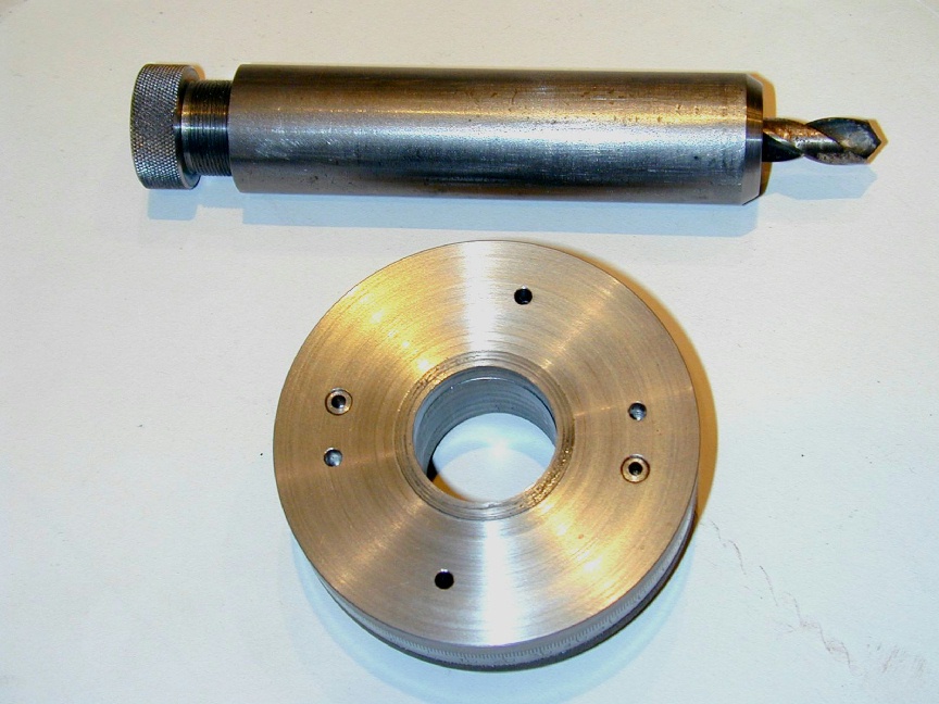 The jig comprises two main components. First, a simple, cylindrical spindle from 1" stock that is bored accurately (in the 4-jaw chuck after clocking for minimum run-out) for shop-made 5/8" diameter collets. Second, an extra index plate that attaches positively to the existing index plate. This plate has two sets of index holes that can engage the Quorn Locking Pin, each 180 degrees apart, but displaced on diameters that are located at 67.5 degrees of arc from each other. In the center of this plate is a register that will prevent it from rubbing on the Quorn backplate (see the Annotated Quorn Photo to picture these parts).
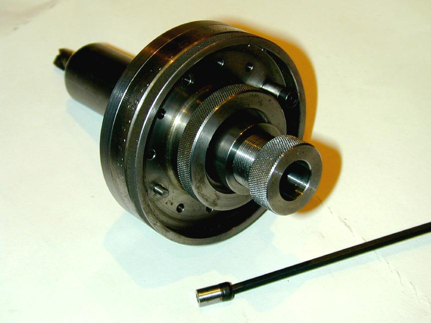
Note the other pair of smaller holes in previous photo. These are in the center of a pair of screwed in pins that align the secondary plate with the standard Index Plate. The end of these 1/8" diameter pins is threaded 5BA so the two plates can be clamped securely together. Rather than use nuts, I made a pair of short 1/4" threaded rods and glued Allen head cap screws into one end—Allen keys generally being easier to find than nut drivers! The photo here shows the index plate assembly clamped to the collet spindle by the existing Quorn tapered split collet and locking ring. All in all, it would have been easier to make the new Index Ring to the same dimensions as the standard one and just swap the split collar and locking ring between them. No graduations would be needed, though a fiducial against the hole pair that are used for the first 4 facets would be useful (we'll come to that in a minute).
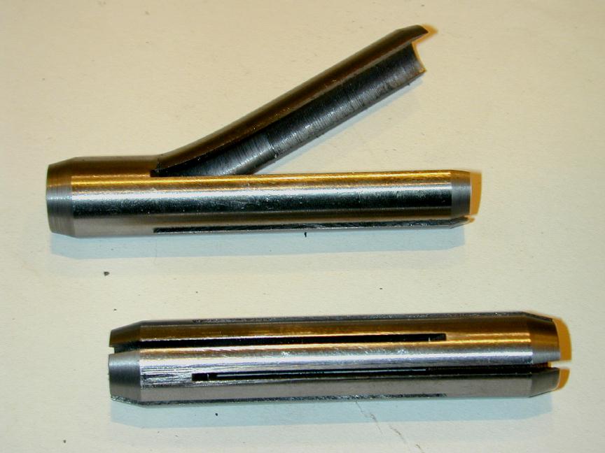
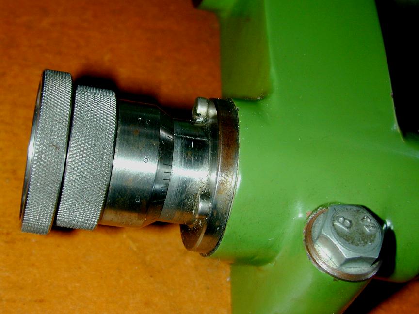
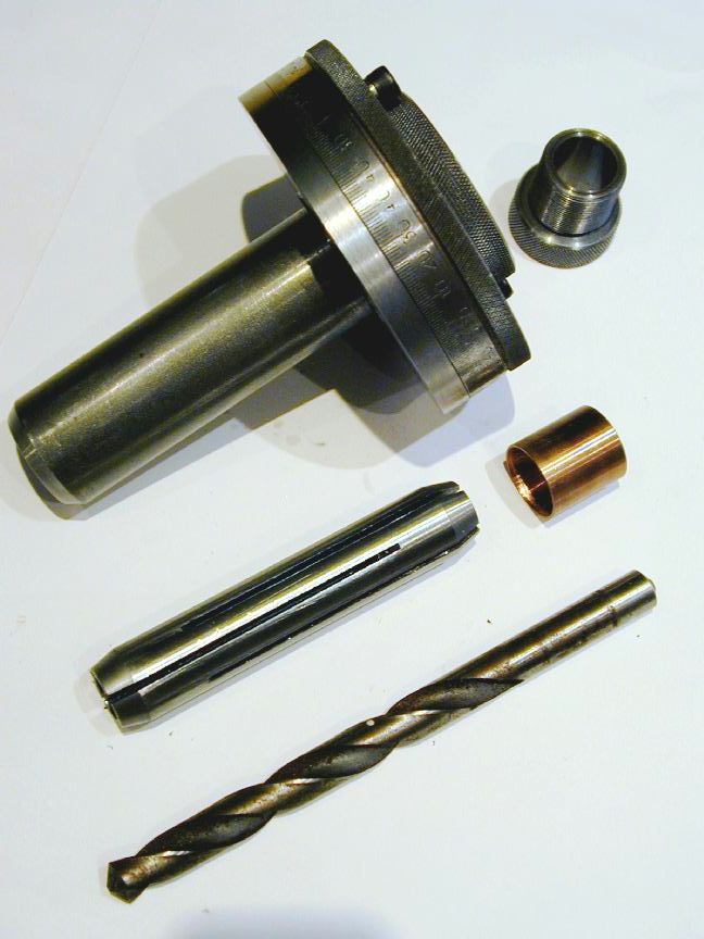 This shot shows the assembled spindle and Index Plate, with one of the drill holder collets. As published, the gadget will comfortably hold drills from 1/2" down to 9/32" in 4 collets (ie, each has a gripping range of 3/64" down from their nominal size). The collets, machined from drill rod, are tapered 60 degrees included at both ends, then slit in interleaving quadrants at either end for close to their length. Obviously, the nose of the spindle carries a like taper to close the "front" of the collet. The spacer to the right of the collet is machined from brass, with a 17/32" ID and another taper that closes the rear of the collet. To the right of the spindle assembly is the collet closer: a steel, knurled knob, just under 1" in major diameter, with a 40 TPI thread (so the index plate can be slid over it) and a bore of 17/32". As noted by Mr Brown, making the aft closer separate from the closing screw tends to prevent the collet closing screw from rotating the collet and drill as it is tightened.
The truly great idea behind this design is that given careful attention to accurate, concentric boring of spindle, collets and tapers, drills will be gripped securely at both ends, and held very accurately in the axis of the spindle in the Tool Holder. This ensures that the drill can be rotated with negligible run-out—a requirement if the facets are to intersect at a single point. Another clever aspect of Mr Brown's design is the design of the spindle allows the whole assembly to be easily withdrawn from the Quorn work head when forming the facets to eye-ball the drill tip end-on. The register on the plate and the index pin ensure that the assembly can be reinserted at precisely the same location to put on a bit more cut. You don't even have to stop the motor!
 This photo shows the purpose of the other pair small diameter holes in the index plate. They are 3/32" so the index pin won't engage them by mistake, and are used to locate a set-up jig to aid in aligning the lips of the drill to be sharpened such that when indexed and locked up, a line through the lips will be parallel to the plane of the Rotating Base. This is essential if the intersection of primary and secondary relief facets is to be parallel to the cutting edge. This part of the design is not quite as good as the rest. But I'll come back to this after describing how to transform the 4 facet tip into 6. To do this we need to grind in another relief, this time at 45 degrees to the plane perpendicular to the drill axis. Due to its mechanical design, the Quorn head will swing at best, 30 degrees from vertical (mine will only go counter-clockwise to 28 due to one of the many cock-ups made building it. See the A Rank Beginner Builds The Quorn). This is where the pair of indexing holes displaced 67.5 degrees from the first pair come into play:
- Perform the steps described previously to create a 4 facet point, then stop the motor, unclamp the Workhead base and slide it right, clear of the wheel.
- Bring the Tilting Bracket back to zero degrees, and swing the Rotating Base to 45 degrees so the drill point is angled away from you. If you are sharpening a number of drills at the same sitting, use the Rotating Base Stops to set these two positions. Swapping between them is then very fast.
- Rotate the Spindle through 67.5 degrees using one of the next pair of holes in the Auxiliary Index plate. Bring the drill up to the wheel, and clamp everything up.
- As before, put on cut with the Micrometer until the new facet being formed meets the intersection of the previous four. Feel free to withdraw the spindle to eye-ball progress as much as you like. Note the Micrometer reading at the intersection.
- Index 180 degrees and repeat. If all is well—and it will be—the final facet will intersect at the same Micrometer reading as the previous one.
Room for Improvement
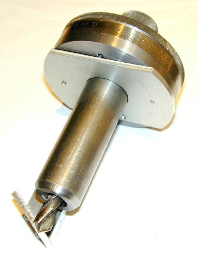
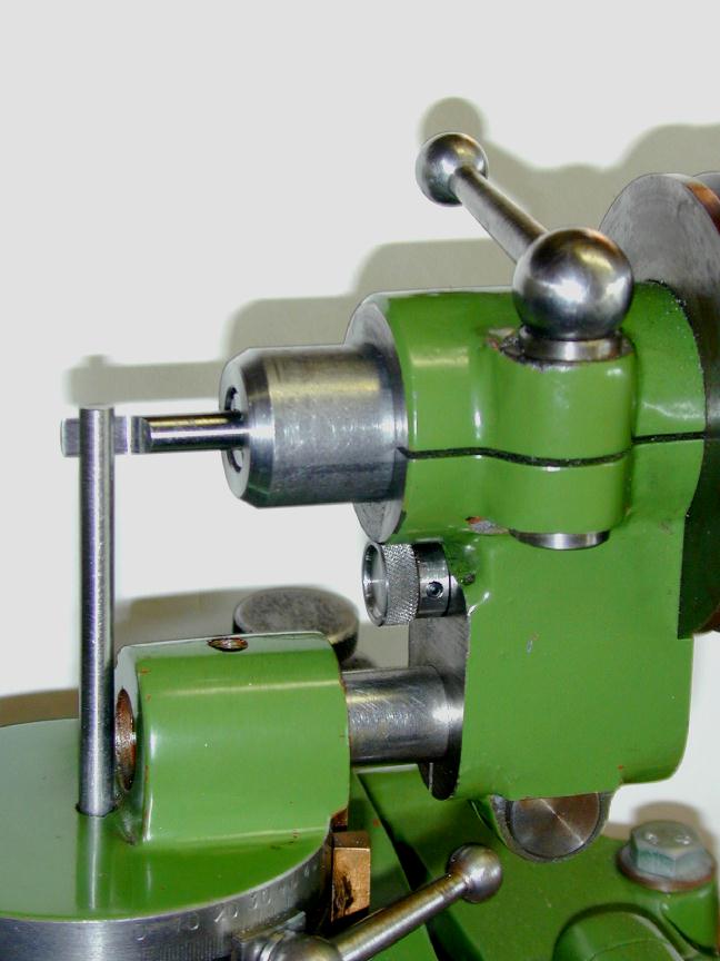
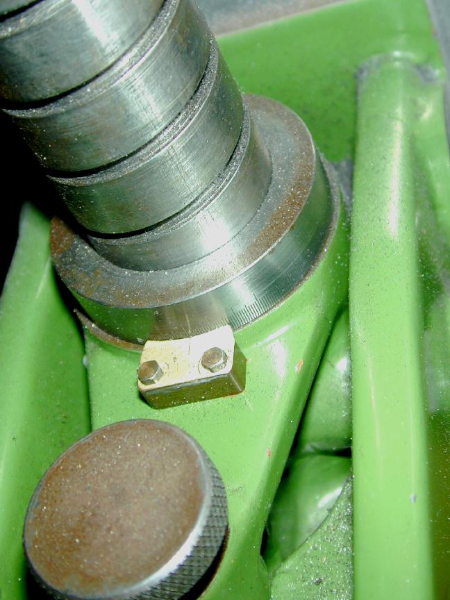
Overall, the attachments work well, but the jig used to set the drill horizontal would work better if I had 3 hands, or took the time to clamp it to the index plate with machinists' clamps during alignment. This sort of negates the idea of simple, quick set-up. This is compounded by the fact that you may have to re-set the drill alignment after making cut #1 if this has to remove a lot of material (for example, to grind back a chipped tip). Because of the spiral flutes, significant metal removes will have the effect of rotating the lips, requiring they be reset. If this is not done, the width of the primary relief will appear to taper towards the margin area. There must be a better way.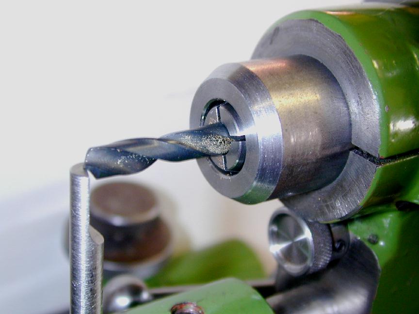 Here is my small contribution to this tool. As a "proof of concept", I'm using the 7/32" setting pin as a rest to align the drill lips. For this operation, the collet has been tightened up to give the required overhang, but index plate is not yet fitted to the spindle. The spindle is just rotated while upward pressure is applied to the setting pin, which is angled to rest on the lip. When aligned, the spindle is clamped, then the index plate fitted and locked up in the "zero" indexed position. After setting, the spindle clamp is relaxed, allowing the spindle to be withdrawn sufficiently to remove the setting pin. Much easier! If necessary, the alignment can be re-checked and adjusted after grinding the 10 degree primary clearance.
A more permanent jig will comprise a 7/32" drill rod pin, fitted with a hardened 1/16" plate "T" piece for the lip rest. Must make one, someday...
I Learnt Something Today
Just like the Quorn itself, making the collets would have been easier if I already had the collets and could shapen my drills (to make the collets, you see...) This piece of chicken and egg-ism was about to get worse.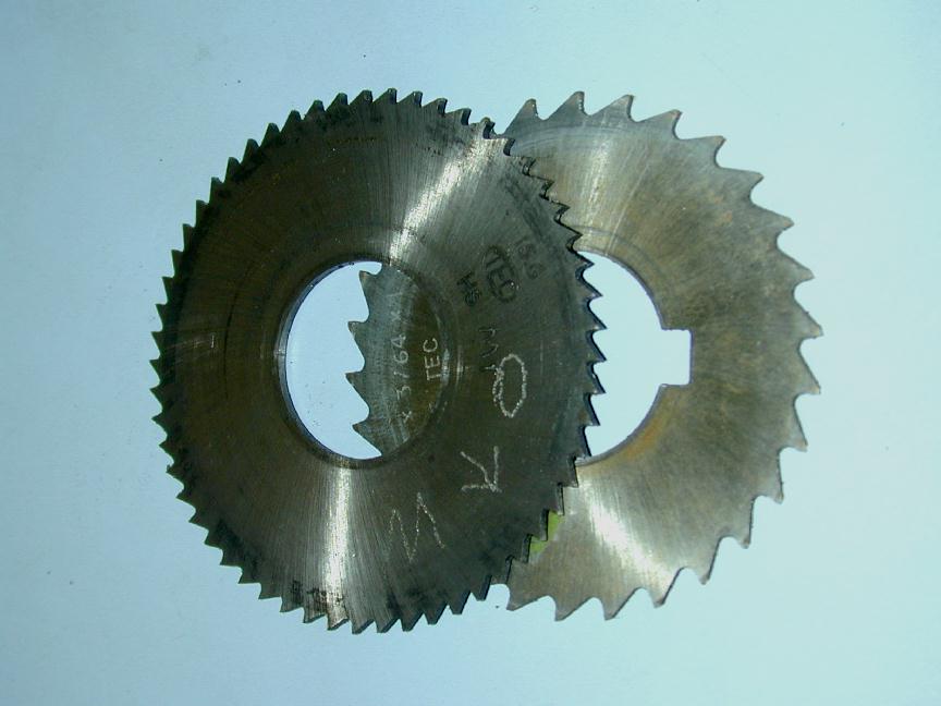
The article in ME said slit the collets with a 0.053" slitting saw (because that is what Mr Brown had, and it worked). It used a 0.063" saw because that is what I had and I hoped it would work. I did, but that saw had made a lot of cuts (it made the Quorn itself) and was far from sharp. After making the first collet (the 3/8" one), if was in a really sad state—noted as the way the head of the mill was being pushed around the column as I tried to advance the cut. But I had another saw, albeit one with a much coarser tooth pitch, so on we went to the 7/16" collet. That cut a lot better and I though I was saved from the prospect of having to make a Quorn fixture to sharpen slitting saws before I could get back to making the drill sharpening collets.
 Next collet to make (following the state of my drill stand contents) was the 1/2" collet. As the OD is 5/8", the walls of this one are only 1/16" thick. As you can see, the coarse pitch saw went OK for the first 3 slits, but had barely touched the surface of the last cut when there was a bang and the noise changed drastically. With probably only one tooth at a time touching the light, slit tube, the collet had deformed at the start of the slits. As they say in the classics—and the TV commercial here downunder—bugger. Now I'm definitely going to have to make that slitting saw sharpening jig, and buy more 5/8" drill rod, before returning to the collet making business.
Stay tuned...
Footnote:
As always, there is another way. The methods described in the following papers describe six step methods for both faceted and conical back-off, the latter deemed impossible on the Quorn by the designer himself! They were devised by Jörg Hugel (Switzerland) and originally appeared on Yahoo QUORN Users' Group. This is an essential list for Quorn owners and builders. It is moderated Carl Carlsen and the documents mentioned, plus many more, can still be obtained from that location. We thank Jörg and Carl for permitting the drill grinding material to be repeated here.- Six Steps to the Perfect Four-Facet Drill with the QUORN Tool and Cutter Grinder (view)
- Six Steps to the Perfect Drill with the QUORN Tool and Cutter Grinder (view)
Jörg provided this background to accompany his techniques:

The method described by my approach is different from Prof Chaddock's recipe, which while easy to understand, has the disadvantage that during the grinding process the positions of tool and wheel head must be altered several times. This is not necessary with the alternative method as after the Quorn s initially set, all further settings are performed with the stops. And as a fringe benefit, if the Quorn is set once you can switch from primary to secondary clearance and from one lip to the other without reading further any scale. The procedure is described in "Six Steps to the Perfect Four-Facet Drill with the Quorn Tool and Cutter Grinder".
Some time later, I realized that, despite the published opinion of Professor Chaddock, it is possibility to also grind also drills with conically shaped flanks using the Quorn. The process is described in "Six Steps to the Perfect Drill with the Quorn Tool and Cutter Grinder". This is a simple recipe and if carefully followed, drill grinding becomes foolproof. There is no necessity to adjust carefully any edges with the drill's axis. I feel it is much simpler to grind drills with conically shaped flanks and they do drill accurate holes.
From discussions, I know there are strong advocates for the multifacet drills. But in my opinion and experience, the self-centering feature provided by the geometry does not vindicate the extra effort required to grind those facets to the precision required. However everybody is free to decide what they like and would prefer. The method and parameters in my charts were found analytically by mathematical investigations for the conically shaped flanks. For the individualist, there are many possibilities to adapt the drill's performance data to special situations which my method could be adjusted to handle, but what do I really do in the workshop? I've ground dozens of drills, always with the same setting data as found in the charts.
References:
| [ME1] |
Brown, D: Four Facet Drill Sharpening: Extending the Range, Model Engineer, Nexus Speciality Publications, England, Volume 177, Number 4025, 20 Sep-3 Oct, 1996, p313. |
| [WPS12] |
Cain, T: Drills, Taps and Dies (Workshop Practice Series Number 12), Argus Books, England, 1993. |
![]()
