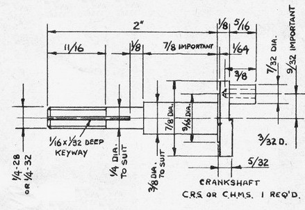
Crankshaft
A welcome relief from filing is offered by the crankshaft and, since its completion will relieve your anxiety regarding ball bearing alignment, we will deal with it next.
 |
 |
- Take the piece of 1 inch diameter x 4 inch long CRS and center drill both ends.
- Set up in four-jaw chuck exactly 9/32 inch off center, projecting 5/8 inch from jaws. Using a heavy cut-off tool, or one similar, rough out the crankpin, leaving a section of material 3/16 inch long at the end of original diameter, thus retaining the center drilling. Finish-turn the crankpin, using a slightly cranked tool to undercut the counterweight, to 7/32 inch diameter exactly. (When we say "exactly" we mean as near as you can get. The word is used in order to avoid stating tolerances which may confuse the less experienced. Most of the dimensions are not critical. Where they are, we say "exactly.") Finally, center drill and drill 3/32 inch to the required depth.
- Remove work from four-jaw and lay aside while making a couple of experimental mandrels from scrap to a binding fit in the ball bearing bores. Check the exact sizes arrived at with the micrometer.
- Next, put the shaft blank between centers and turn to drawing, using the sizes found where the drawing says "to suit," remembering to compensate for crankcase error on the 7/8 inch dimension. You can go between size and minus .010 inch if the crankcase is within the limits. Screwcut the 1/4 inch thread and then take a half-thousandth cut, starting 7/32 inch from the crankdisc, right along the 3/8 inch portion, and another half-thousandth cut, 7/32 inch from the shoulder, right along the 1/4 inch portion, including the thread.
- Set up three-jaw and cut off the lump on the crankpin with a hacksaw and clean up
with a file. Cut off shaft to length and, if necessary, run a die over the thread.
The above may seem an odd way to make a shaft, but the disadvantages are offset by one big advantage. The heaviest cuts are made when the workpiece is strongest and the crankpin will finish up true with the main shaft, without an involved set-up procedure. - The crescent counterweight left by undercutting the crankpin should be filed so that its edge is straight across the shaft center line.
To check all alignment, press the large hearing onto the shaft, using a piece of tube on the inner race and, having oiled the crankcase housing, press the shaft and bearing gently into position. Check that the shaft spins freely and then insert the small bearing, using pressure one both bearings if possible. If the crankcase was correctly fitted on the mandrel and did not move while cutting, the shaft should now spin freely. Any slight "lumpiness" can be eliminated by carefully tapping the bearings or shaft.
The keyway can only be cut by milling and, if possible, should be used in preference to the following alternative, as it is ultimately easiest to make and does not materially weaken the shaft. However, if facilities are definitely not available, a flat filed on the 1/4 inch diameter of the shaft, starting 3/16 inch from the shoulder and giving a final measurement of 1/16 inch when gauged in terms of shaft thickness, will do instead.
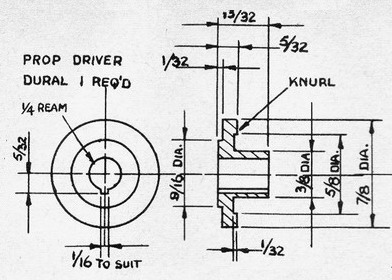
Prop Driver
Machining this component is straightforward and where the keyed drive is used, the keyway can be filed by hand to suit a McCoy Redhead key. However, if the flatted shaft drive cannot be avoided, the prop driver should be drilled 1/8 inch through the center and the hole then filed out to suit the shaft. By filing the flat side of the hole first and then cutting the remainder to suit, a concentric fit can be achieved with a little care.
