Building the Morton M5
![]()
See the M5 Reference Page for a description and history of this engine.
 THIS PAGE UNDER CONSTRUCTION
The Starting Point
Together with an original engine (serial number A511), I acquired a partially machined set of original castings for an original M5 (Morton offered "kits" to schools and amateur engine builders). I've no idea when work was started on this, but I can guess why it stopped as the quality of the work done is poor, indicating either a lack of appropriate tools, skill, or both!
Drilling the Crankcase
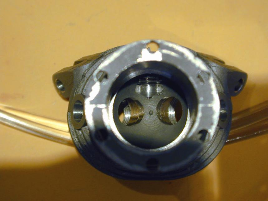
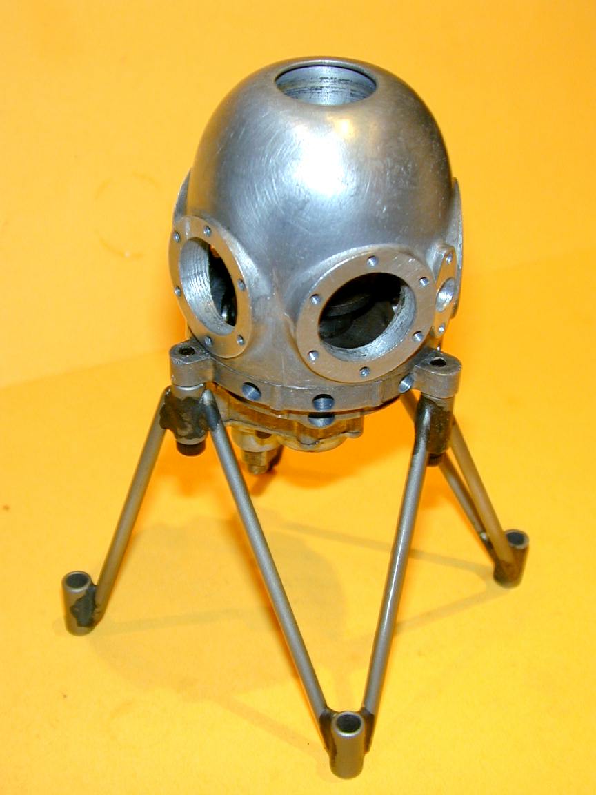 The picture here shows the case looking like a lunar lander with portholes. My contribution has been drilling and tapping mounting holes for 4 of the 5 cylinders, plus the carby flange, and drilling and reaming the tappet and fuel pipe holes in the gear case. I also had to drill and tap the 3 mounting lugs which had been partially butchered. You can see the sad state of the machining in the bore visible on the #2 cylinder. They all look like they've been bored using a rusty nail held in a pair of pliers and one of them is distinctly egg-shaped! It also looked like the cylinder flanges had not been machined when these "bores" were cut, so my only option here was to lap the flanges using 600 wet and dry paper on a surface plate and hope for the best.
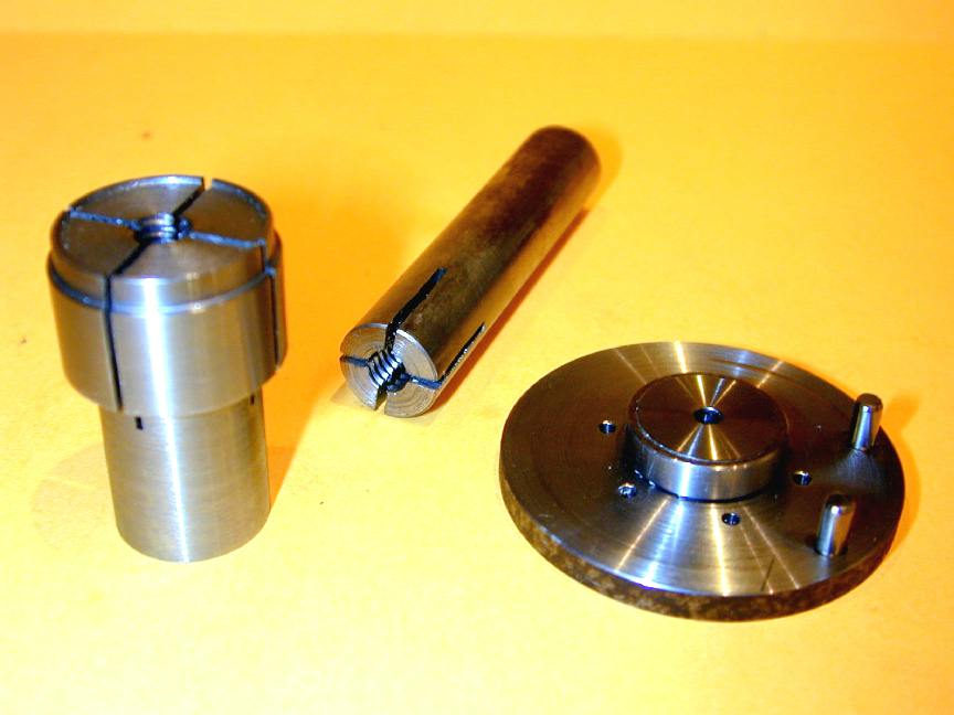
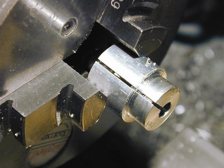
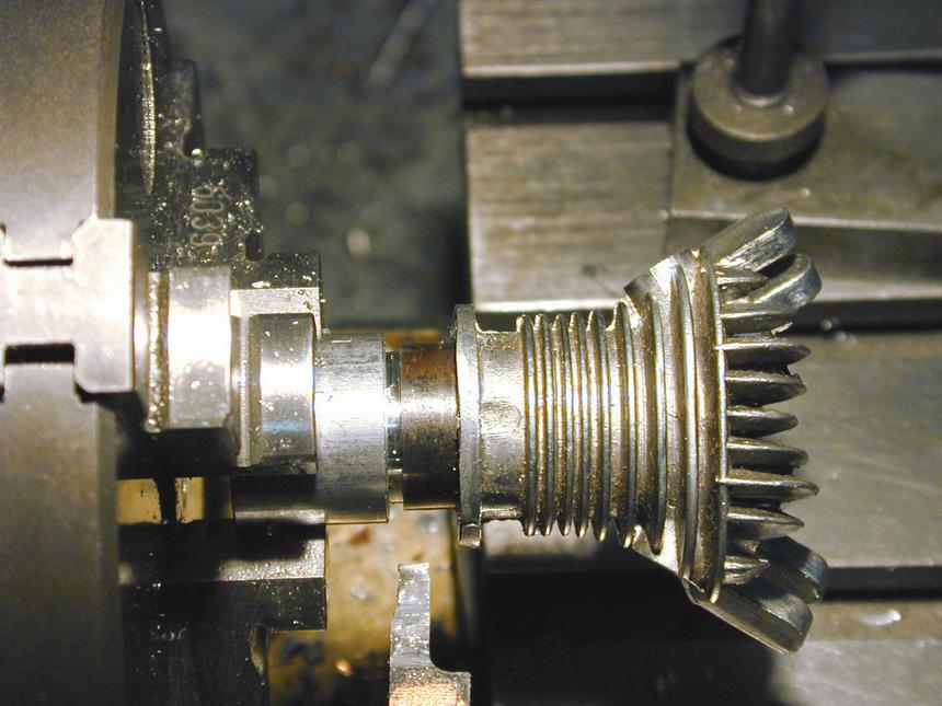
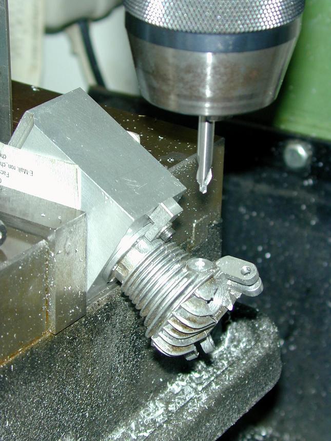
The tooling shown here comprises two expanding arbours to grip the gear case on the cam bearing and the front case on the main bearing bore (this bearing is a "rattling good fit" that can be fixed with Loktite, I hope). They are expanded when a 1/4-20 cap head screw encounters the tapered portion of the thread cut by a 2nd taper tap. The fancy end on the large one serves no purpose: I "recycle" a lot of temporary tooling and that shape is left over from an earlier usage. These allowed each part to be gripped in the 3 jaw chuck and trued up with a DTI in the lathe by applying judicious tapping before transferring to the rotary table under the mill for drilling operations. The other thing is a drilling jig for the cylinder bolts. The two pins bear snugly against the rear face of the case to align the jig correctly.
While drilling and reaming the gear case, I discovered that the Morton drawings are a bit "theoretical"! They show all inlet pipes and 1/2 the tappet guide holes as in-line with each other fore-aft. That's the way I did it, so now I have the inlet pipes nicely centered in their bosses and the tappet holes all rotated a couple of degrees from left-right symmetry with their intended cylinder! It won't matter running-wise (at least I don't think so) and though the push rods will not sit at the same angles to each rocker, it will be hard to spot unless pointed out. Naturally, after I finished drilling, then cursing, I looked at the "factory" engine and found they knew about this and did not follow their own drawings! The inlet pipes break thru into the gear case on a step in the casting. This is guarenteed to make a drill wander, and those holes need to be round to get a good, "wringing" fit of the pipes themselves, so they were drilled with a ball-nose 3/16" slot drill which is far more rigid than a twist drill.
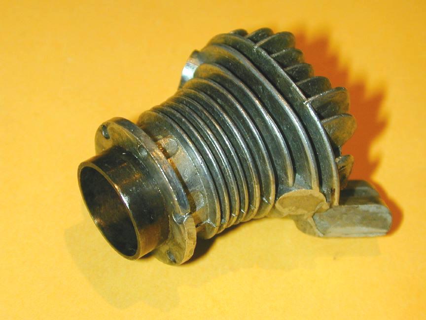
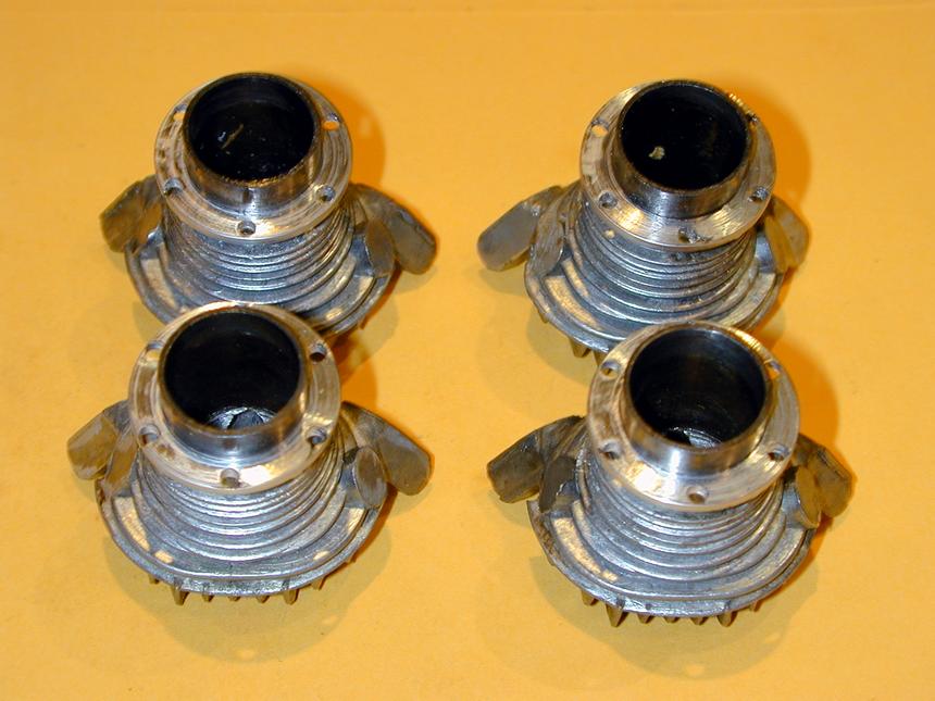
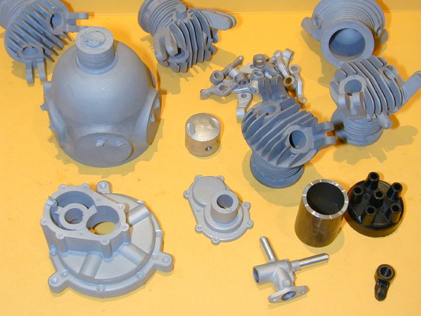
This picture shows an original, un-machined Morton cylinder. Note that the steel cylinder liner is cast in. Compare this with the Satra cast cylinders which use short sections of chrome-molly tube, ground to the correct bore and assembled to the (finished) cylinders with high-temperature Locktite adhesive. This allows the bottom of the cylinder casting to be skimmed normal to the bore--a virtual impossibility with the original design. Note also how the cylinder mounting holes in the flange of the Morton unit are cast-in, and how the metal has not flowed completely around the flange on the one nearest the camera. I assume the Morton company was aiming for faster and cheaper production here at the possible expense of a little esthetic quality. Coming from a war-time mind-set, this is quite understandable.
As mentioned in the Satra castings section, machining the cylinder castings is easily the most complex job on the Morton and the most complex aspect of this is workholding. The Morton casting requires four different jigs for this task. As nearly all machining operations are performed with the cylinder mounting flange as the reference, this needs to be cleaned up first as it is not perfectly flat and probably not perfectly at right angles to the cast-in liner bore. First the mounting holes are cleaned up with a #42 drill held in a pin-vice.
The other difference between the castings was the provision for the exhaust/inlet tubes. Vernal cored these very close to finish size. Morton simply provided un-cored bosses, requiring the holes to be completely located and drilled. This was done using a 3/16" slot drill to finish up a hole drilled 11/64" to get a close, smoothly finished hole into which the pipes will be "wrung" to obtain a gas-tight fit.
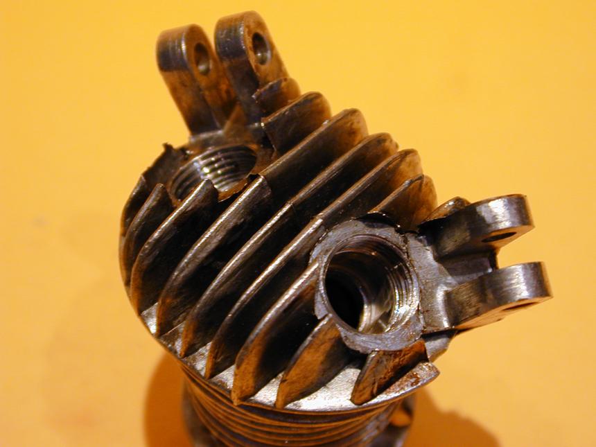
Just for complete lack of consistancy, the sparking-plug hole of the Morton is cast-in, while Vernal use this area as the casting gate (come to think of it, I've no idea where the metal entered the die for the Morton castings!) This is better than the Vernal approach as the cavity in the combustion chamber that must be drilled for the Vernal head, has been cast in for the Morton. This circumvents the need for the half-in, half-out drilling operation required for the Vernal heads. Drilling onto a step will pull the drill off center--not serious here, but not nice either.
Back to Building the Morton M5
This page designed to look best when using anything but IE!
Please submit all questions and comments to
[email protected]
Cylinders
 The first jig is a throw-away tapered mandrel, as once removed from the chuck, it could not be returned accurately enough to be used. It comprises a parallel section that is a close sliding fit in the cylinder bore, with a short tapered section at the chuck end that will jam in the liner enough to withstand cutting forces. The springy slit is left over from its previous life as a failed crankpin machining jig serves no purpose in this case.
 The flanges are faced with a left hand knife tool to the drawing dimension of 0.078". This mostly cleaned up the casting with only a little area around the outer edge of some screw holes missing out. Certainly the under face is now as flat as I can get it. Enough to provide a good seal with a paper gasket and all are as close to normal with the bore as they are going to get. The cylinder material does not machine as nicely as the Satra castings--not as bad as the AHC castings, but getting a fine finish is difficult. Perhaps I was a bit harsh on the guy who originally machined the crankcase.
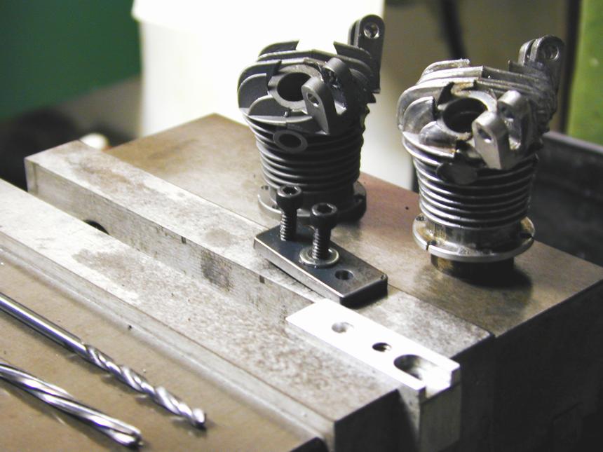 The operations to drill and ream the rocker posts of the Morton castings for the pivot pins are identical to those on the Vernal castings and the same jigs and set-up were used. The photo here shows a Vernal and a Morton head with the holes drilled (the Morton head has the cast-in liner).
 Similarely, the valve cage recess machining used the same jigs, although the castings in this case differed from Vernal. While Bruce's investment castings have a taper sided hole with minimal, but adequate metal to be removed, the Morton castings were very, very close to finished size, making aligning for machining rather tricky. I suspect the Morton factory may have used a special, stepped reamer, hand held, for this operation. The shot here shows the drilled rocker posts and tapped out cage recesses.
![]()
