Morton M5
![]()
| Name | Morton M5 | Designer | Glen L Morton |
| Type | 4 stroke ignition radial | Capacity | 0.92 cuin |
| Production run | 1440 (approx) | Country of Origin | USA |
| Photo by | Ron C, of Model Museum engine | Year of manufacture | 1940's |
Notes:
The Morton M5 is four stroke, spark ignition, five cylinder radial engine (using the usual master/slave rod arrangement), based on the full size LaBlond radial. It was designed by Glen Morton of Morton Aviation in the 1940's and was sold both as a production engine and a kit. Later, versions were made from original parts by the Burgess Battery Corporation as the "Burgess Morton M5" and others (the full story is very complex). It has also been the subject of at least two totally separate fully built reproductions. Reproduction investment castings are still available from Bruce Satra who documented the lost wax mould making process in SIC several years ago. A meticulously researched account of the M5, it's designer, sibling engines and everything else was researched by Bob Knudson and published in ECJ volumes 13 and 14. Some think the LaBlond was an ugly engine. Well beauty is in the eye of etc, and personally, I think the resemblence between the LaBlond and the Morton in very tenuous. Incidentally, LaBlond also made fine lathes and Glen Morton's company also made light planes and machinary.
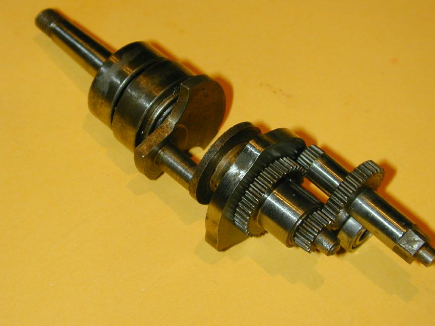
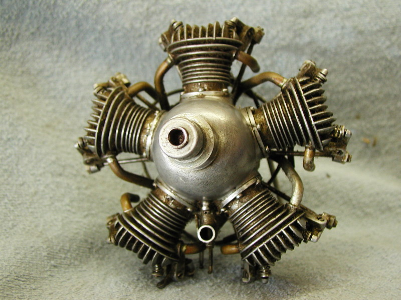
One unusual feature of this engine is the cam design. Normal practice for a five cylinder radial would be to provide two five-lobe cam disks, connected together and rotating in the same direction as the crankshaft at one half the crankshaft speed. One actuates the exhaust valves, the other the inlet. The M5 (and presumably the LaBlond) achieves the same result with a single cam that has three lobes, revolving in the same direction as the crankshaft at one sixth engine speed. The photo here shows how this is achieved: a pin on the aft crankshaft engages in a hole in the master crankpin. The gear on the aft end of this shaft drives an idler shaft at one half engine speed. This is used as the points cam and to drive the distributor arm. A gear on the inner end drives the valve timing cam through a further 3:1 reduction. This cam and its drive gear are attached to a bronze bushing that actually rides on the aft shaft. The large bearing area aft of the cam drive gear rides in a bronze bushing in the rear engine casting, so we have a shaft riding inside a shaft, axial with the crankshaft. This results in a more compact design that places all valve push rods in the same plane. I've never understood why it is not more widely employed.
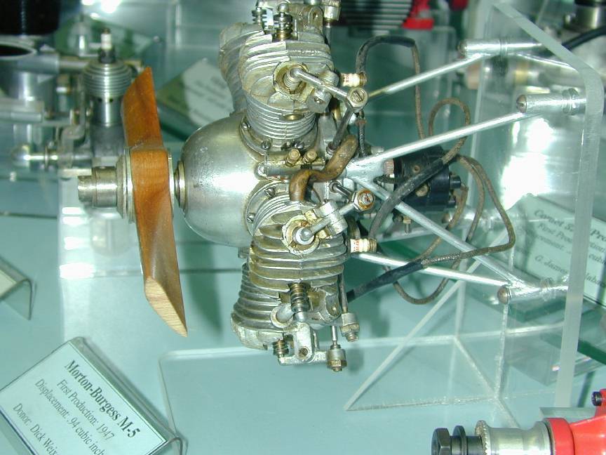
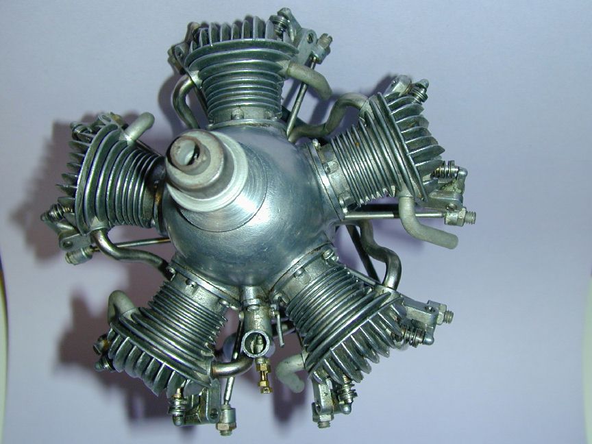
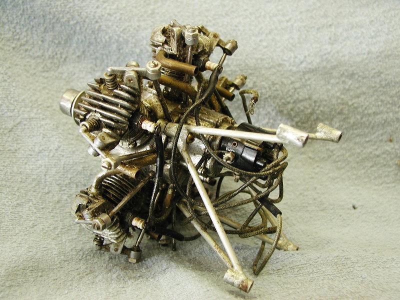
This M5 was photographed in the San Diego Air and Space Museum, located in Balboa Park, SD CA. The front 3/4 view shows the engine as displayed, but it has been mounted rotated 90 degrees counter-clockwise -- the carbeurattor should be at the bottom of the engine. Perhaps the curator mounted it this way to make details of the carby easier to see. The exhaust stub pipes are missing and the induction pipes appear to be a mixture: I see one plated one and one (very beat-up) un-plated one. The second shot shows the nicely made, original motor mount. Very similar to what would be found on a full scale engine of this type in a light plane of the 30's. Note the plaque that claims a 0.94 cuin capacity -- I think this may be wrong.
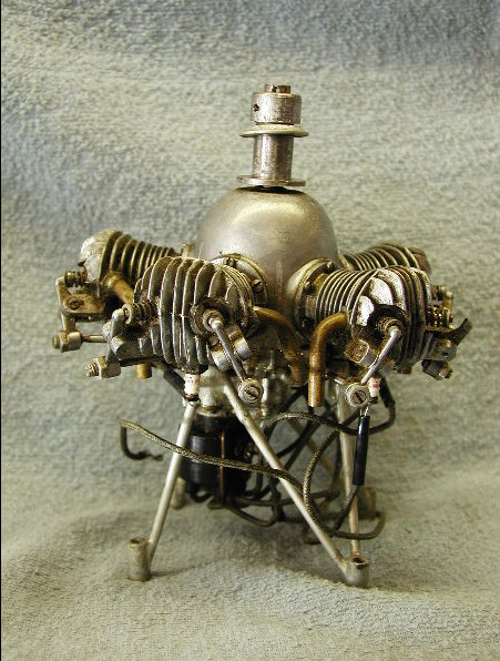
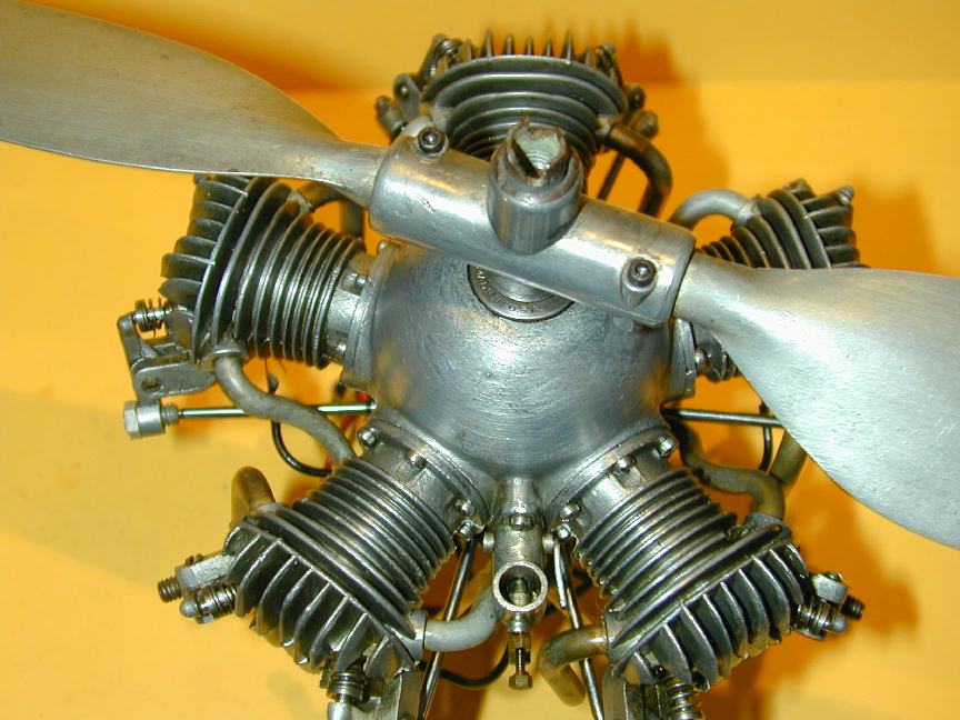
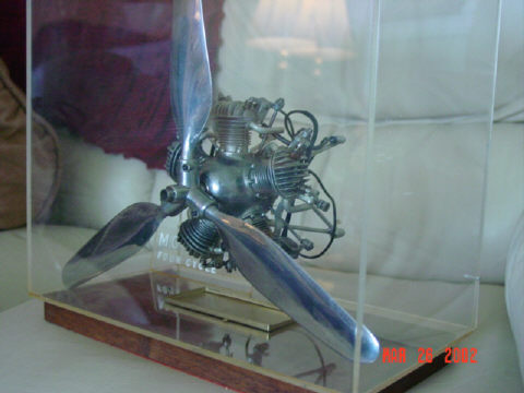 An email from Dario Brisighella who's owned a number of M5's notes that the Achilles' heal of the M5 is loss of crankcase seal through the front bearing. There are two ball races supporting the shaft, separated a short distance by a spacer. Both are "sealed" type bearings, but the rear seal of the front bearing and the front seal of the rear bearings are removed and the volume between the bearings packed with grease before assembly at the factory. When the engine is running, the crankcase acts as a plenum chamber with pressure below ambient allowing the updraft carburator to draw in fuel air mix. This mix is drawn into cylinders through the inlet pipes positioned around the gear case cover on piston downstrokes in the normal 4 cycle way. Ballbearing dust seals are just that: dust seals, so the reduced pressure in the case assists gradual migration of the grease into the case over time. Eventually, enough grease is lost so that air readily passes through the bearing seals, reducing the pressure differential between the crankcase interior and the outside, resulting is less suction through the carburator, giving a leaner mixture. Performance eventually drops off to the point where the engine will no longer start. At this point, many owners took their engine apart with no idea of what was wrong, or of the critical setup of gear positions required to get the timing correct. The three-blade prop on Dario's engine was a factory option (a two-blader was also offered). Note how closely it resembles the Hamilton-Standard ground-adjustable pitch props of the 1930's. Beautiful.
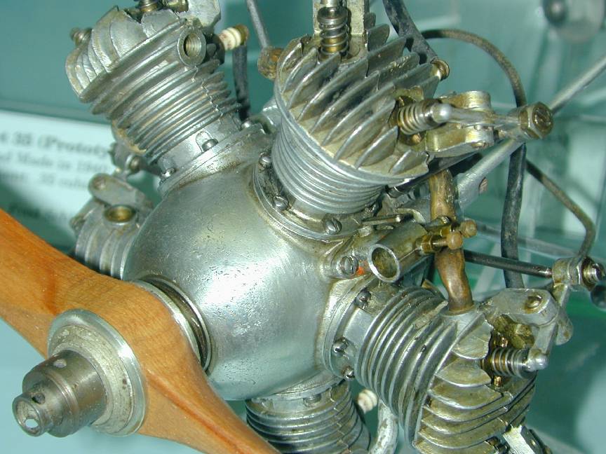
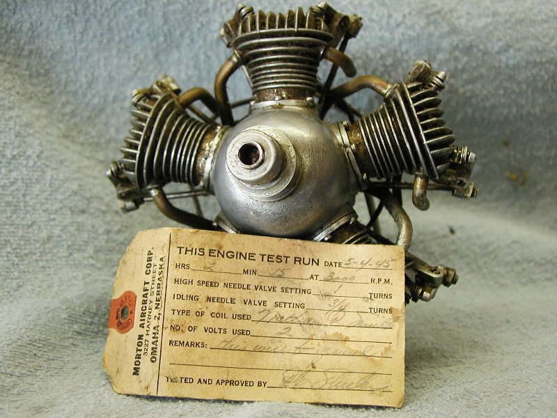
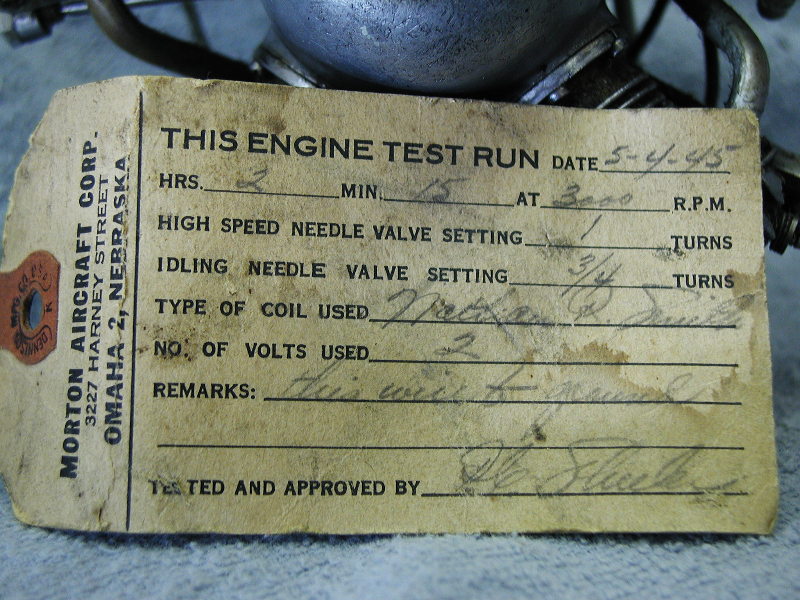
Next we have some excellent pictures of a very original condition Morton M5 sent by a gentleman who had done a web search and found this page. This engine had been bought new by his father back in 1945. Note the duration stated for factory running: over 2 hrs at 3000 rpm!
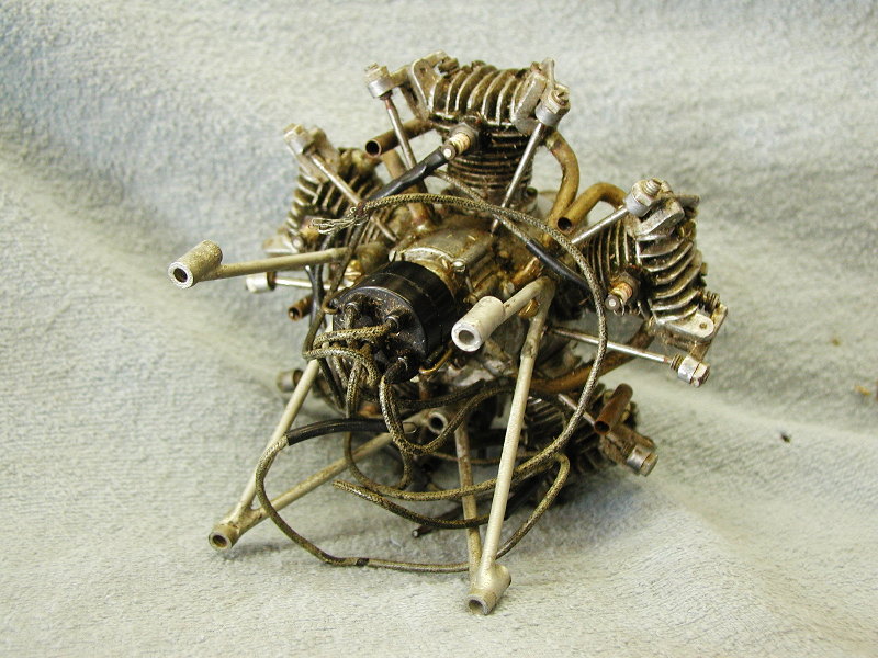
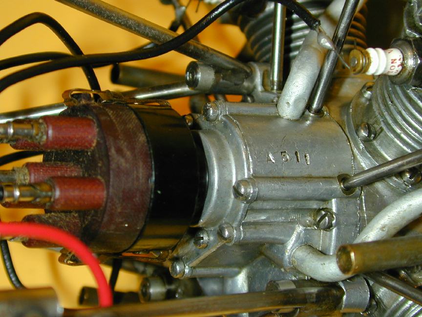 This M5, serial number A511, is now in my own collection (and to think, I started out as an engine builder, with no interest in collecting). The "A" prefix denotes a "premium" engine, meaning that when factory tested, the engine started and ran particularly well. This must have made other owners feel rather second-class! The photo here is pritty much as received, though the Morton 2 blade prop was not fitted and I had to make some rather special tools to remove the "flying" prop hub. I also suspect that the distriburor cap and wiring are not original, although the clips retaining the cap may be. The cap has been nicely fabricated from phenolic material and uses (I think) pins from early 8-pin valves on the distributor leads, plugging into valve socket receptors in the cap. The serial number is a relatively early Morton factory one (visible on the gear case) and the spark plug clips are neat, but not of any type researched by Knudson in his ECJ series. There is no advance/retard facility; again, an indication of an early, Morton manufactured engine.
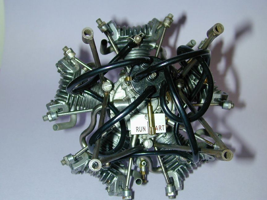
It can be a fun exercise to trace the distributor leads from cap to cylinder as this gives some indication of how much the owner knows about the engine. The firing order on all conventional radials is: all odd number cylinders, followed by all evens. Coincidentally, this is what gives "round" engines their characteristic exhaust sound--remembering it will take two crankshaft revolutions to fire all cylinders. Conventionally, the cylinder poking up at top is cylinder #1. Normal rotation on most full-size radials and the M5 is counter-clockwise when viewed from the front. The cylinders number sequentially, in the direction of prop rotation. So, viewed from the rear and moving clockwise we, see 1-2-3-4-5. The distributor cap numbers for the Morton represent the firing order, but number counter-clockwise because the rotor arm is rotating in opposite direction to the prop. The firing order required is 1-3-5-2-4, so to time the engine, place the crankshaft so the "top" cylinder has both valves closed and the piston at TDC. Wherever the rotor arm is now is the #1 cylinder firing position. Now select the next counter-clockwise distributor flylead and connect it to the #3 cylinder counted clockwise from cylinder #1, viewed from the back. Flylead #3 goes to cylinder #5, #4 to #2 and last, #5 to cylinder #4. Got it? Have a look at the rear photo of Tim's engine. His engine is wired up correctly.
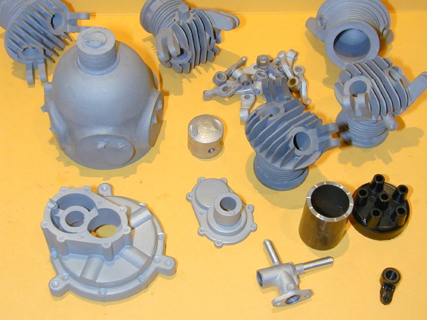 I've been asked by a number of people where they can get Morton parts today. Now, you must realize we are talking serious rocking-horse droppings here. The original Morton and Burgess parts dried up long ago, but in recent memory (early 1990's), a talented tool and die maker named Bruce Satra embarked on the ambitious task of reproducing the dies to make Morton parts. This process was well chronicled in the first volumes of SIC magazine. Bruce's dies are used to produce parts through "lost wax" casting and the detail as seen here is superb. Can they be used as replacement parts? Probably, but as their finish is different and detail better than original, they will stand out on an original engine. Bruce's company now supplies many parts for the M5, as well as an exact 1/6 scale Pratt and Whitney Wasp Junior; a 9 cylinder radial. Ask Bruce for his latest catalog by writing to:
Vernal Engineering Co
2277 So., 1500 West
Vernal, Utah 84078-4654

(435) 789-6052
Together with the A511 engine, I acquired a partially machined set of original castings for an original M5 (Morton offered "kits" to schools and amateur engine builders). The standard of work already carried out can charitably be described as adequate to poor, although the worst mistakes appear to be salvagable. The engine is missing castings for the rocker arms, pistons, master and slave rods, and carburetor. All these can be made from stock, if I can't locate replacements. I'm keeping the M5 construction log separate from this information page as I expect progress to be slooow...
![]()
 Home
Home
This page designed to look best when using anything but IE! Please submit all questions and comments to [email protected]