| WORKSHOP HINTS AND TIPS |
|
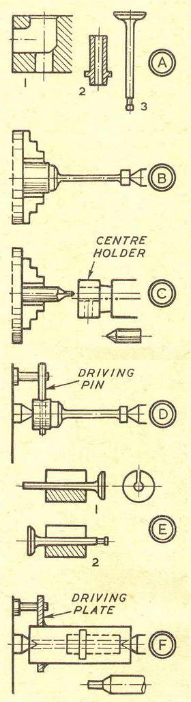
Points About Poppet ValvesBy GEOMETERTHIRTY years, almost to the week, after the publication of my first article in ME, I read in the November 15 [1962] issue of a querist's difficulty with loss of compression past the valves of a Kiwi. What memories it stirred—this perennial problem! In the long-ago I had the same exasperating trouble with my model, and finally overcame it by using a seating cutter. This twin was my first move into internal combustion engine practice, after I had made several steam engines. It was an exercise in ingenuity with features that broke almost every rule of normal construction. Except for the two cylinder heads and the flywheel, which were castings, everything was from odds and ends. I lacked cash as well as experience, but I was inspired to try my hand by the petrol engine articles written by an encouraging dispenser of wisdom whose name was Edgar T. Westbury. To say that my twin—with all its faults—eventually worked reasonably well is only to pay proper, though belated, tribute to his influence. Inevitably I learned much from that model with the leaking valves; and from this and later experience, I evolved two simple rules for success. First, you must have the geometry right; second, you must not rely on force to achieve your ends. To prove my points, I evolved a Chuck-like method of testing. With a valve fitted, I put the port in my mouth, sucked hard, and plugged the end of my tongue or a piece of my lip in the port. If I could then dangle the cylinder head indefinitely, I knew that there was no leakage. If it fell off immediately, something was not right. The sealing of the balance pipes on Jowett Javelin flat-four engines was checked on a similar vacuum principle. As for geometry, consider diagram A and the implications. At 1 is a typical port with a bore for the valve guide and a seating for the valve. These must be concentric. If they are not, the valve will not seat properly—although a seating cutter can be used to bring about concentricity. At 2 is the valve guide, which must be concentric inside and out—or you will have the same problem, and can adopt the same remedy, as before. At 3 is the valve. Its stem must be straight and the seating concentric with it; otherwise you must correct the error or make a new valve. Now consider how we may be tempted to use force to achieve our ends. You can rough turn a valve stem, drawing the billet in stages from the chuck, and finally steady from the tailstock for finishing, as at B. But force from the tailstock will true a wobbling centre, and you will turn a valve with a bent stem. On the other hand, you may have a lathe with a dropped centre, giving the same trouble. If you do, and you wish to employ this method of turning, you should make a mild steel centre holder, as at C, centring and drilling from the chuck for a hardened silver steel centre. If you employ the alternative method of turning between centres, you can drill the billet for a driving pin, as at D, to avoid using a heavy carrier. You can face the head of the valve, and turn the collet groove, using a split bush, as at E 1 and 2. In grinding-in a valve we must not rely on the pushing or pulling force to correct geometrical errors and produce a good seating. We may have one that looks all right, but leaks. Nor must we rely on the force of the spring to correct errors—for it is unlikely to be capable of that. Diagram F illustrates a method which I have adopted for turning bronze valve guides concentrically. Begin by drilling and finishing the hole with the material in the chuck. Face the ends true, and make a centre in each with a piloted cutter, or lap the centres with a piloted stub, as shown. This eliminates the chance of error from a wobbling centre drill. Then you can fit a driving pin, or solder on a driving plate, for turning the outside diameters between centres. Providing that the valve guide bore and port are concentric in the cylinder head (item A1), you have accurate geometry and a valve that seats without leakage. |
|
|
Back to Geometer Index Page.