| WORKSHOP HINTS AND TIPS |
|
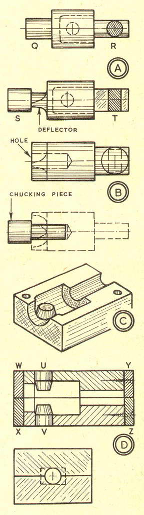
Piston Patterns and Core BoxesBy GEOMETERIN two recent articles I described how a small piston was machined from solid light-alloy because I had no casting and lacked a core box which could be used for the interior of one. If I had had a core box, the pattern—as I mentioned—could have been quickly turned in wood, for it would have consisted only of three diameters. My decision to machine the piston from solid was perhaps better, in the circumstances, than the alternative of making a pattern and core box to obtain a casting, though as a rule the opposite is true. If several small pistons are needed, it is advisable to make a pattern and core box to avoid the inside machining. This applies if a piston of medium size is required, for the larger the piston the more metal must be tooled from the inside when it is machined from solid. You have only to look in a small commercial piston to realise what would be involved in the process. On the other hand, piston castings can be machined in small commercial sizes. This may mean that a small commercial engine can be kept running when a new piston is needed but no replacement is on hand. You solve the problem by making a pattern and core box from which you get a casting. This you machine on the lathe. The cylinder is bored by a specialist firm; and if you cannot find piston rings from among the many sizes (including oversizes) that are obtainable, you have them specially made. Any hard wood, like oak, beech and boxwood, can be used for small and medium-sized piston patterns, core boxes and similar parts. I mostly use well-seasoned beech. It turns cleanly with a raked tool and can be smoothed with fine glass paper. The normal shape for a piston pattern is as at A (upper diagram). It serves for four-stroke pistons, flat-topped two-stroke pistons, and deflector two-stroke pistons when the deflectors are machined from solid. You make the length of the centre part to requirements and leave the diameter oversize for shrinkage and machining. Diameter Q is a chucking piece which is repeated on the casting. Diameter R IS a core print whose purpose is to make a depression in the mould by which the core can be located. It is round when there is no need for the outside and inside of the piston to be in a given angular relationship. For a two-stroke piston with cast-on deflector, the core print must be rectangular, as at A (lower diagram). Then the deflector and gudgeon pin bosses are cast in correct alignment. Diameter S is a chucking piece which is sawn off the casting when it has served its purpose of providing a hold for a roughing cut. The portion on the deflector is filed away. Section T. which is the core print, is sawn and filed or machined from the round section on the pattern. The main part of the pattern is turned as at B. upper diagram, with a hole drilled down the larger diameter so that the chucking piece (lower diagram) can be glued in after the deflector has been shaped. Diagram C shows part of half of core box with a plug for the gudgeon pin fitted in the boss. For the main part of the core box, you need two rectangular pieces of hard wood, the same section and length. First you dowel or bolt them together. Then, mounted in the four-jaw chuck, they are drilled through. After this, you bore the pieces with a tool from the topslide. You leave the core extension (C, right) round for most pistons. At the front end, you bore the pieces to the diameter of the piston above the gudgeon pin bosses. Beyond that, you open out to the skirt diameter. Illustration D (upper diagram) shows a section of a core box. Each half is drilled for a glued-in plug for a gudgeon pin boss, U and V; and the ends are closed by screwedon pieces W-X and Y-Z. For a deflector piston, you leave the core extension small and then cut it rectangular, as in the lower diagram. |
|
|
Back to Geometer Index Page.