Model Engine Gallery Page 10
Click on the images to view them larger size.
|
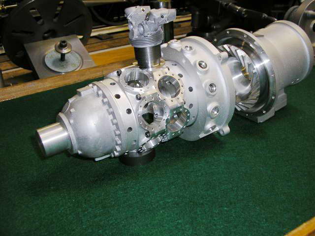
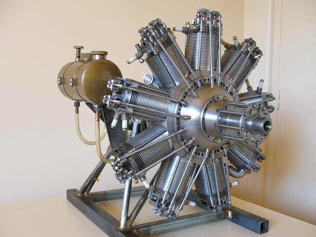
This is a sneak peek at a 1/6 scale model of the Pratt & Whitney R-1830 dual-bank, 14 cylinder radial being built by Ron Harris (USA). The lost wax castings are being produced by Bruce Satra (Vernal Engineering, Utah). The center three crankcase sections are machined from solid, as are the blower ring and gear box, blower impeller is a slightly modified from a used Garret turbine. The engine has a bore of 0.875" and a stroke of 24mm, so every camp is satified! The engine will have a scale electrical constant speed, controllable pitch prop. I count 12 tapped stud holes on each cylinder base (168 total). |
|
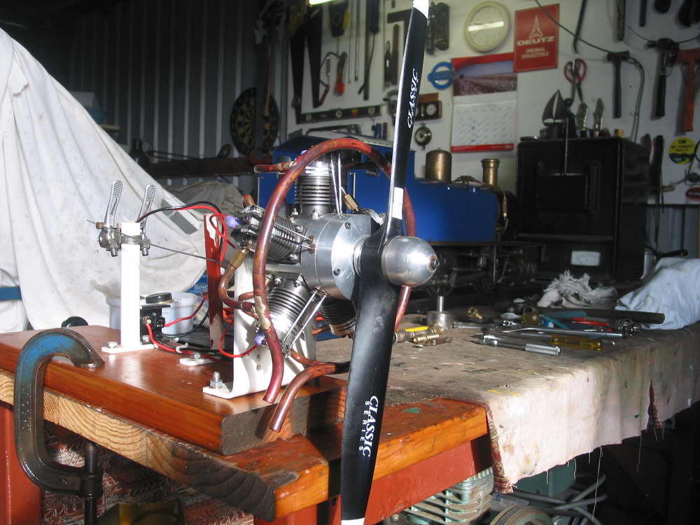
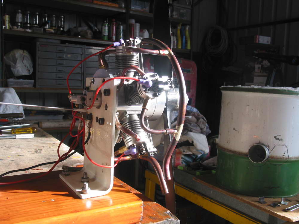
These photos and descriptive text were sent in by Model Engine News Member, Ken Dines. Ken shows that you don't have to start off with simple, single cylinder two-stroke. Of course, it helps if you know what you are doing to start with...
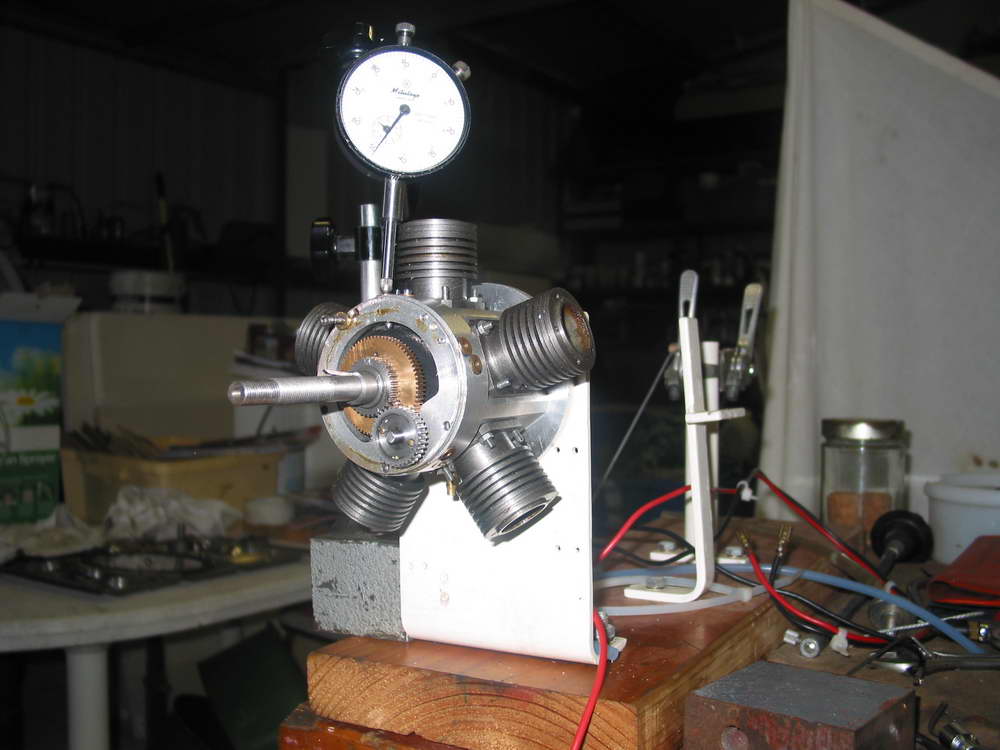
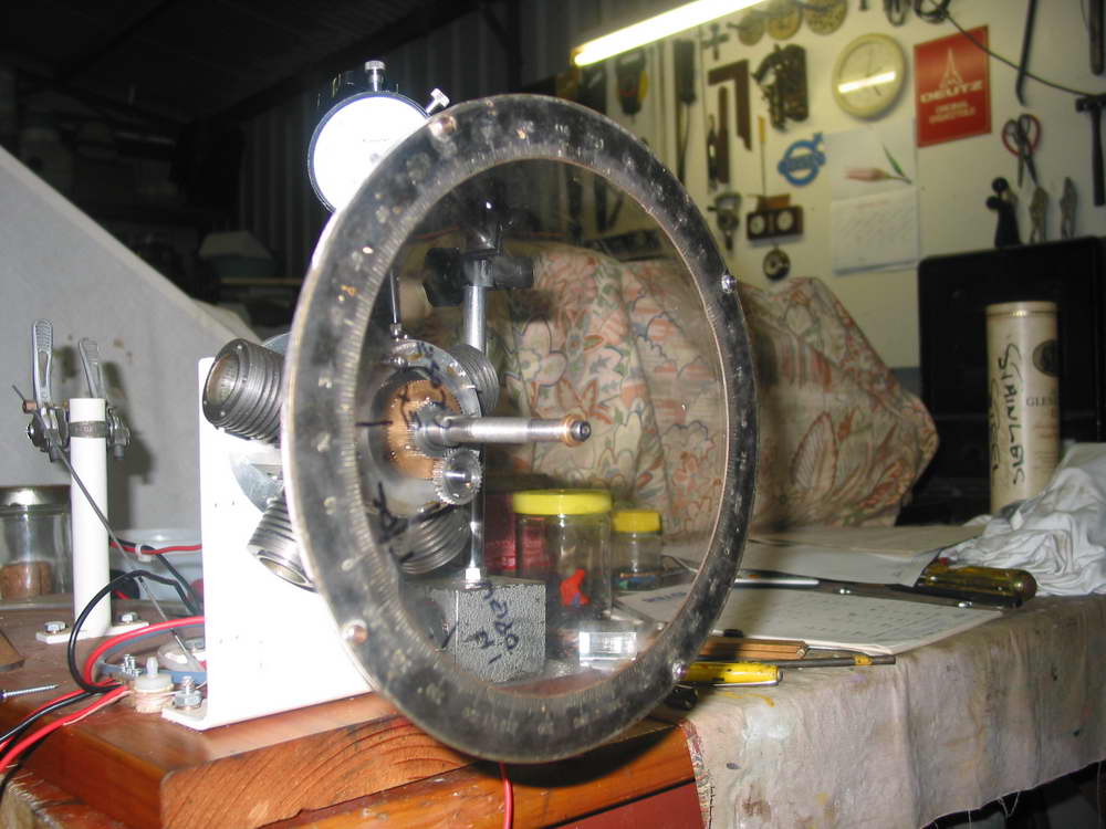
The following is my experience in building a five cylinder, 38cc, four-stroke cycle. radial IC engine. First my background. I was involved with automotive and heavy earthmoving machinery, mainly with engines from 10hp to 1000hp up until my retirement some years ago. During this time I have been interested in models, mainly steam and small IC engines. The opportunity came on retirement so I could pursue this hobby. First I built a 5" gauge steam loco (a "Simplex"), then an 8 cc four-stroke spark ignition engine. These projects sparked my interest in building a radial engine as I wanted to know how they work. The plan was obtained from a friend in UK of a 5 cylinder radial to which I made several modifications, mainly to the induction system and valve rockers. Having a Southbend lathe and a Mill-drill I set about it. The crankshaft was made first, followed by the crankcase, cylinders and cylinder heads. I left the rotary cams to last. They required four internal gears to achieve a ratio of 6:1. As the gears were not obtainable I made two hobs so the gears could be made by the rotating method on the mill. Valves were made from stainless steel and pistons rings from cast iron. Assembling the engine was quite straight forward. Valve timing took some time as the gears and cams are enclosed which meant "assemble and try" several times. Carburetion was from a proprietary make as recommended but caused some problems so I made an air bleed type which worked quite well. As the engine has 5 cylinders it therefore has 5 glow plugs, which require some 15 amps at 1.5 volts to light them up. It took some research to find a suitable 2 volt 20 amp capacity battery that was suitable. With all parts assembled and ready to start the big day came. It is not possible to start the engine by hand, therefore I had to resort to an electric drill which proved satisfactory. Eventually after fiddling with fuel and air mixture the engine fired and performed successfully. KEN DINES, June 27, 2006 |
|
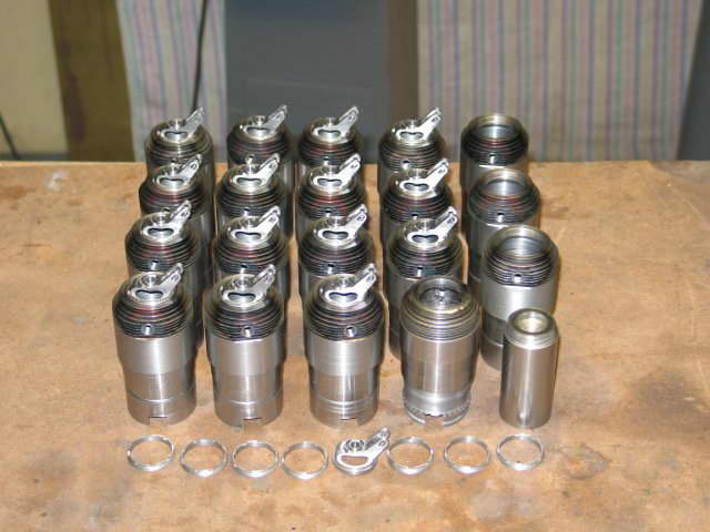
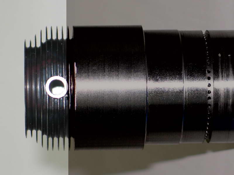
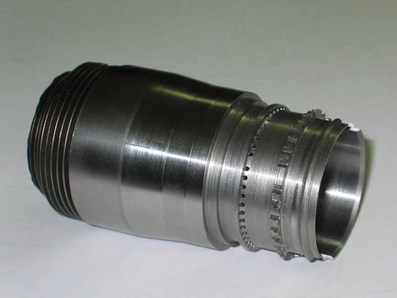
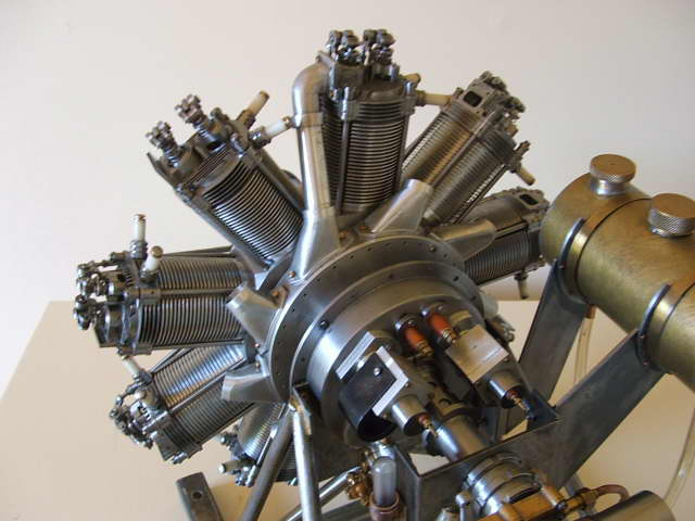
Murray Lane (NZ) has been working on a this double bank, 18 cylinder Gnome rotary for
quite a while—extended because he is demanding the best authenticity
possible. Murray sent these photos in April 2007 and the following words to place it all in perspective:
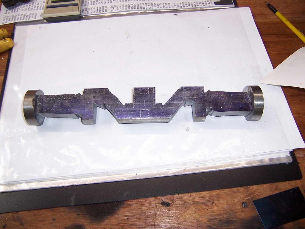
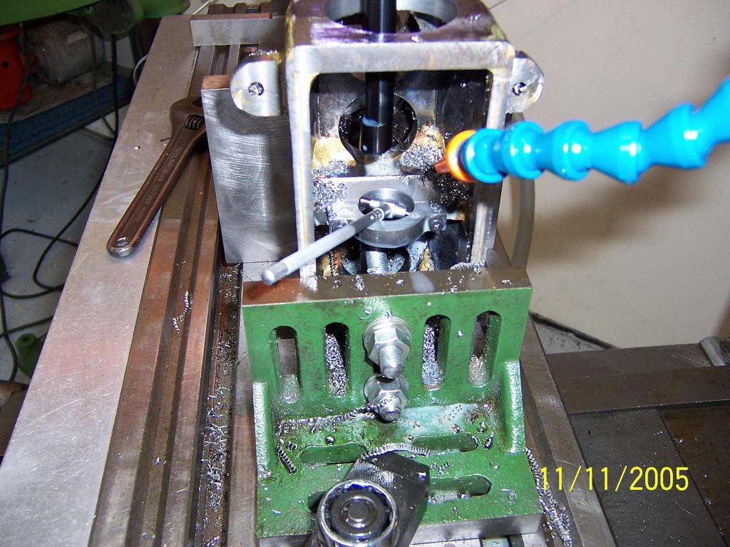
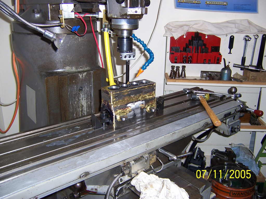
The top photo shows all the cylinders. They are made from 4140 alloy steel. The bar in the front right is the test male thread plug for the internal thread in the top of the cylinder head. All cylinder threads were screw cut to fit the gauge. The photo of the individual cylinder head shows the thinness of the fins, 0.4 mm, which were cut with a special parting tool, and the tapers with a double tool which cuts both sides of the fin at the same time. Note the bottom of the grooves is radiused. The sequence of the machining of the cylinders is critical re holding for the individual machining operations. ie The flat top for the spark plug bush is machined before drilling the hole. The fins are then turned, the spark plug bush is then tig welded in place from the inside. Bit tricky but the welds are perfect. The welding of course hardens the alloy so it cannot be machined afterwards. I write machining procedures for work like this and these are modified to suit when carrying out the work. At present the machining steps on the experimental cylinder are up to 88. The valve cages are cut from solid free cutting steel and it took 2-1/2 hours machining time for each one. There is at least 48 steps. After jigs, methods, and scraped items (about 9) are added, any machining time can be multiplied by a factor of three. I understand Tony Walshaw's statement in the 15/4/77 Model Engineer article, about his 1/5 scale mono, when he said that a number of these ended up in the box under the bench. I have 16 good ones but only require 9 for the front row cylinders, the cages in the rear row are completely different. The base of one the experimental cylinder that I do all the initial work on is finished and it has also has the bore ground to size, 36.66 mm. is shown in the third photo. Drilling the transfer ports (1.25 mm dia) took about an hour on the first cylinder and four drill resharpenings in the milling machine. This was reduced to 11 minutes using a simple dividing head and two drill resharpenings for 882 holes, in my high speed bench drill. |
|
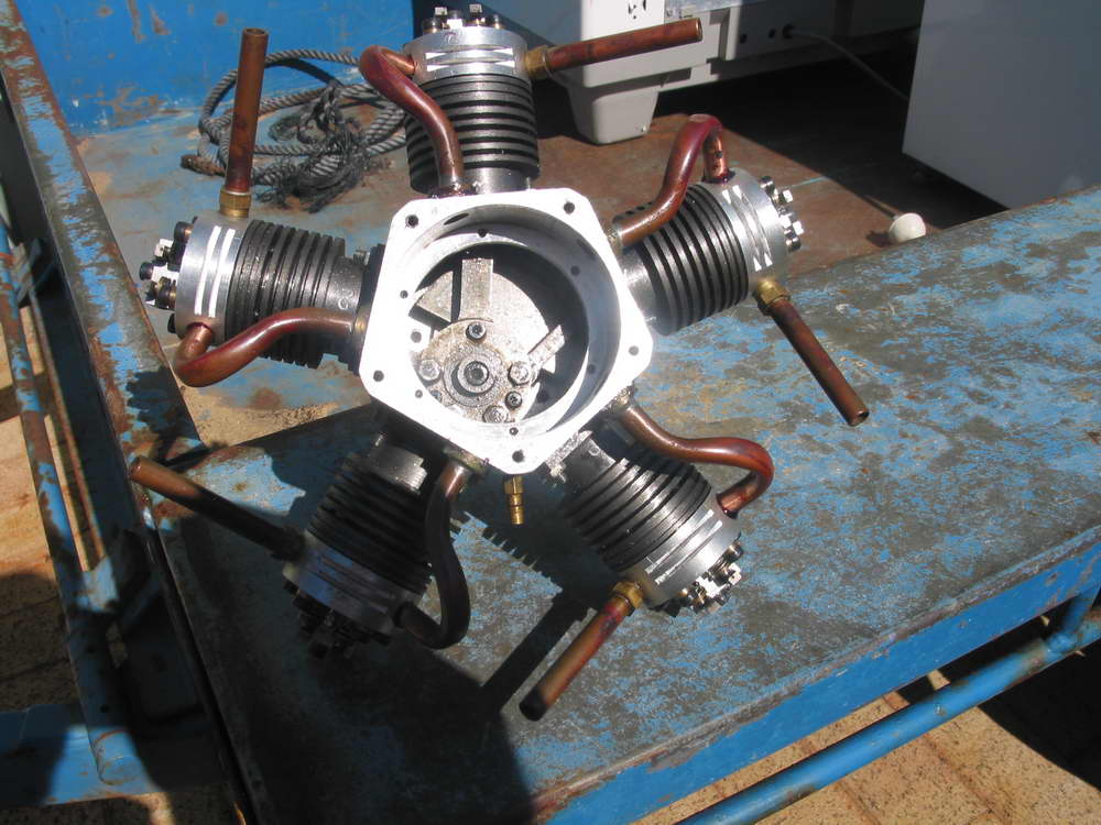
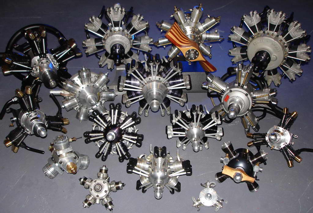
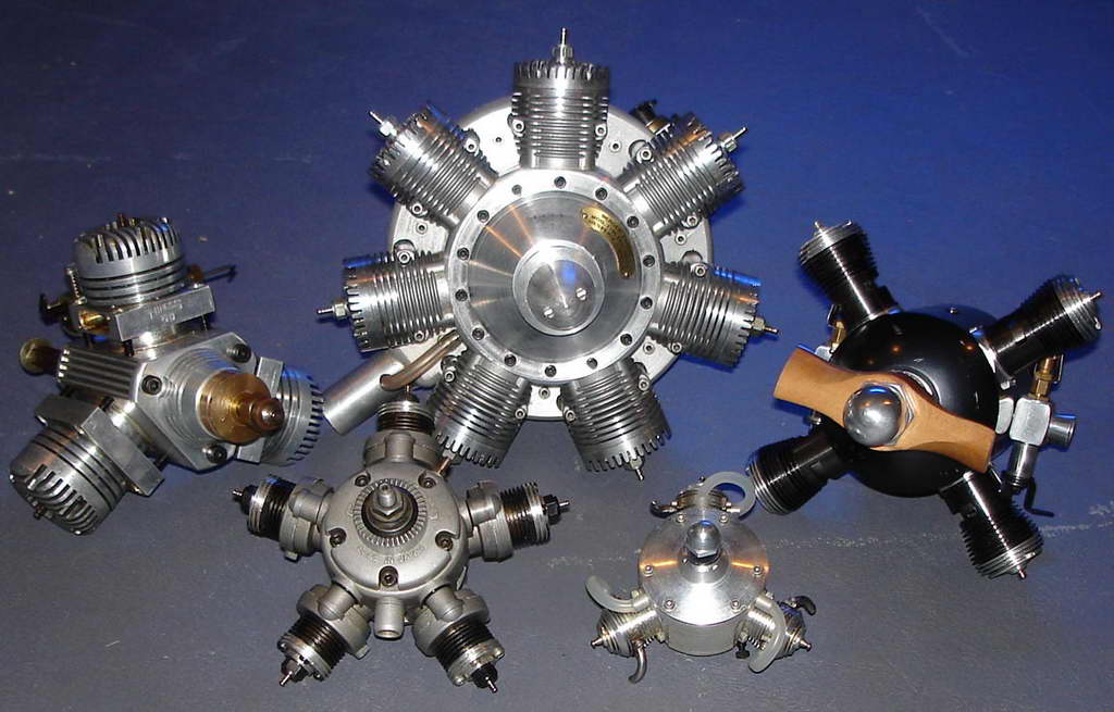
It seems that there is a pattern to collecting, regardless of what the subject of the collecion may be. Most collectors don't suddenly decide to start a collection, they acquire something, then another, and another. Before they know it, they have a capital-c Collection and have become a capital-c Collector. There are stages to collecting too. Initially, a collector will collect anything that fits their chosen subject—be it model engines or stamps! The next stage is to refine the collection to a specific subset of the broader category. The photos here are an excellent example of a "mature" and mouth-watering collection. The category is model engines, while the sub-category would be best termed round engines. The top picture shows the entire collection. The one below shows a collection within a collection: two-stroke radials (extra points go those who can spot the other sub-category exemplified by a single example). The photos were supplied by Steven Satkiewicz. Steve says he's financed the collection and avoided the divorce court by buying motors by the lot, cleaning them, then reselling them. |
|
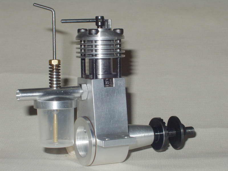
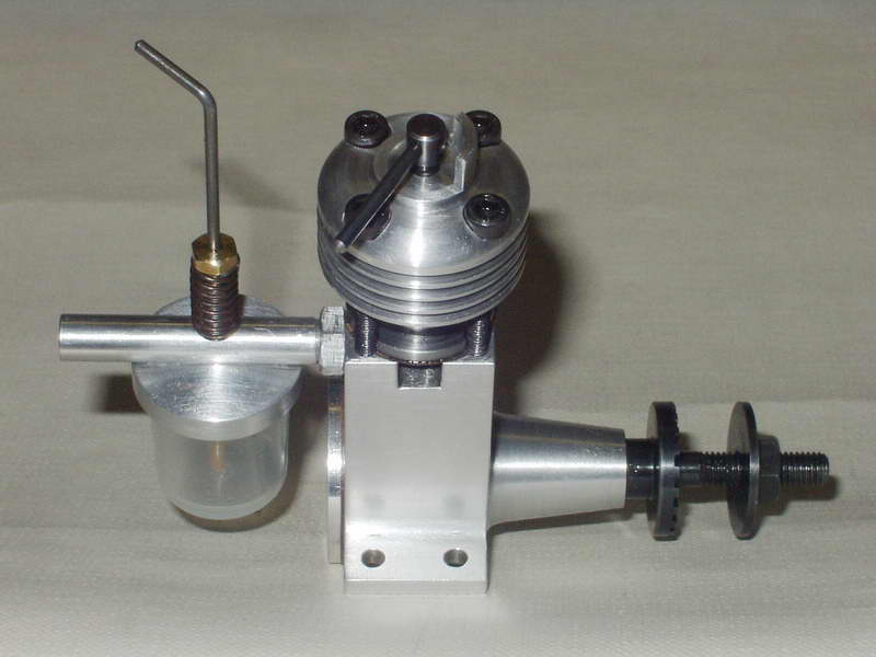
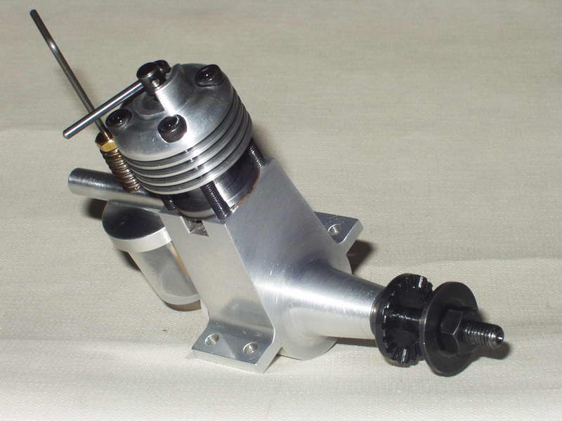
This engine was made by Richard Jackson (Dorset UK). He calls it an "Allourchey/Mills" and I'll let him explain why:
I started the crankcase in a fit of enthusiasm as soon as your article in MEB came out, then it went into the pending tray while I built 2 Midges and a Sparey .8, I decided I did not really need another Mills as I have some originals, so as Mills blatantly copied the Allourchey I built one based on your Mills design. The main differences from your drawings are that I raised the deck height and made the con-rod longer to suit, the head and liner are held down by long bolts, the taper on the bearing housing is greater, the threaded portion of the crankshaft is longer and my favourite features are the head with built in compression stop, the castellated prop driver and fuel tank /venturi which is much prettier than the Mills. I did not copy the Allourchey flanged 2 bolt venturi fixing (too much like a steam engine part). Every picture I could find was different so this is my version; not a replica; but in the spirit of the original. If you look at the line drawing in Model Diesels 1946 (page 67) the draughtsman must have had it taken from his drawing board before he was finished as the exhaust ports are not drawn and the mountings are not complete! I started it up today and it runs very well, just by way of comparison I ran my Mills 1.3 series 1 and they are very similar to handle but the Allourchey is slightly louder. |
|
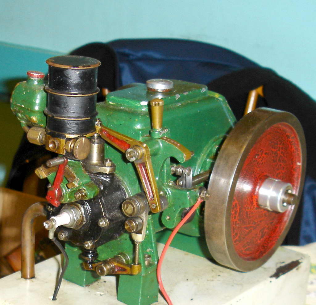
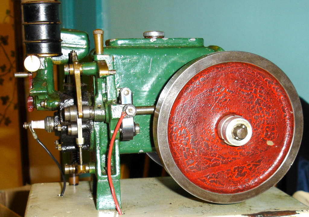
It may look like a stationary engine, but that's just because the rest of the Aveling Type DX Road Roller is slightly missing! There was a time when castings for all of this magnificent beast were available. They even survived the bombing of London during WWII and could still be bought in the 1950's. No longer, I'm afraid. This has not stopped other model engineers who have become obsessed with this design from building replicas, full and part, by using fabricated replacements of the complex castings. But this one is the Real Deal and from the fine patina on the flywheel, it may have been built in the 50's or even earlier. |
|
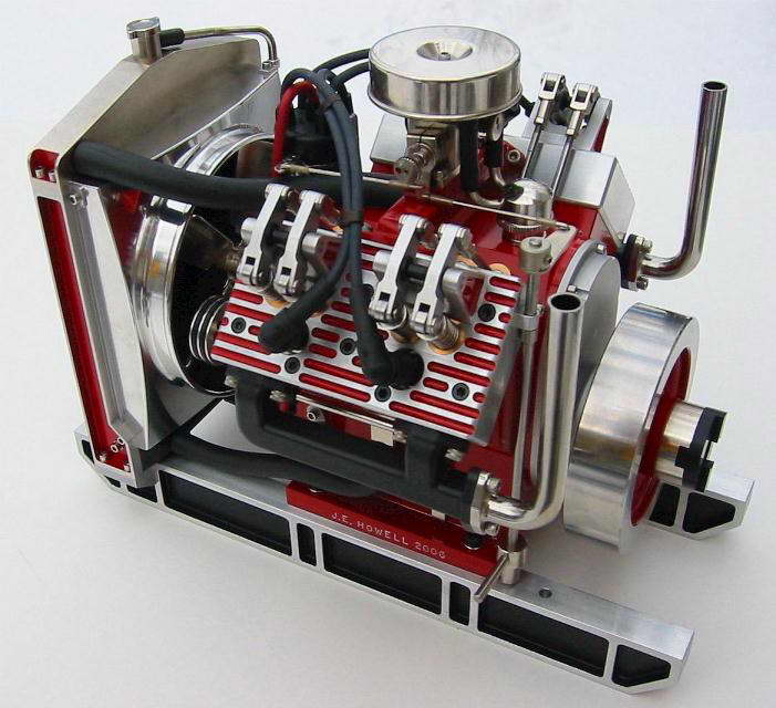
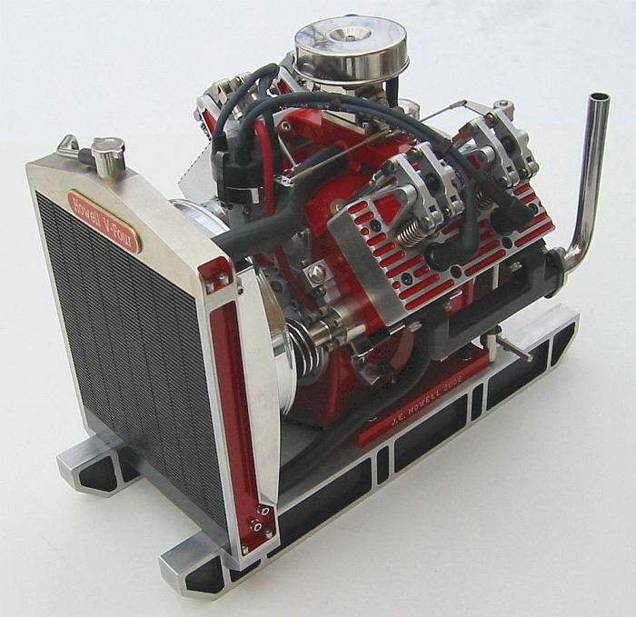
In case you have to ask, this is Jerry Howell's justly famous V4. Jerry sells full plan sets for this and other engines. The following description is taken directly from Jerry's Web Site:
The engine is 1.95 Cu. In. (32cc) in displacement. Cylinders are 90 degrees apart in order to have the engine balanced for vibration free running. The cylinder bore is .875" and the piston stroke is .812". The cylinder banks are not staggered and robust knife and fork connecting rods are used. The multi segment built-up crankshaft and twin cam shafts are amazingly easy to make. A Hall Effect distributor is driven off the end of one of the cam shafts. The distributor body is linked to the throttle arm for spark advance/retard with the throttle setting. The throttle is my proven 2-jet design with an oiled foam air cleaner. Pressure lubrication to the rod ends is by an external gear oil pump which feeds oil through the drilled crankshaft. There is an oil pressure adjuster and an oil pressure gauge port. The engine is water cooled using my unique magnetic drive water pump which has no seals to leak, and a proper looking and effective shop made radiator. The fan blade shroud insures that the 5 curved blade fan actually pulls air through the radiator fins and not just circulate the air around behind the radiator as would otherwise result without one. There are ball bearings on the crankshaft, timing gears, camshaft, distributor, rocker arms, water pump, oil pump and fan shaft. All external parts are sealed using "O" rings which prevent any oil seepage from the engine. A crankcase vent/check valve maintains negative crankcase pressure. A dipstick is provided to monitor the oil level and also an easy to get to oil drain plug. |
|
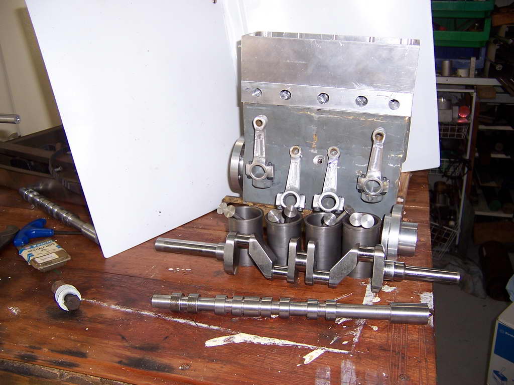
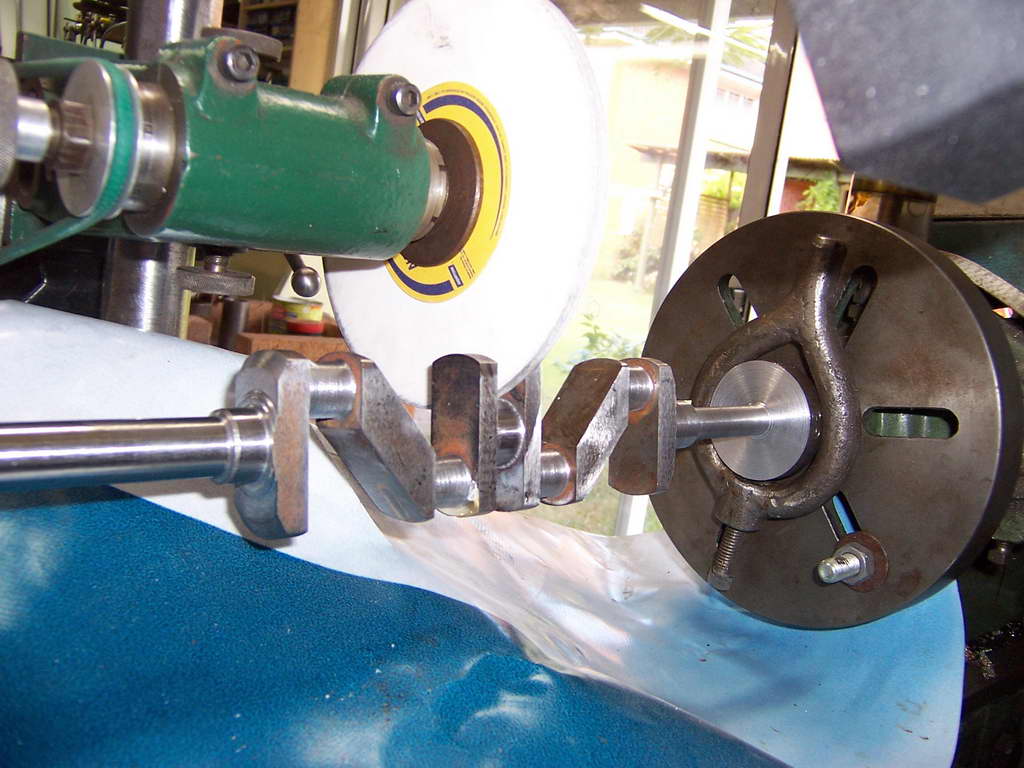
Mike Ruska hales from my own part of the world and has been working on a scaled up ETW Sealion, which is a scaled up Seal. He's even managed to find a categorically justifiable name for it. Here is the message that accompanied his photographs:
I started building the engine which I have called Walrus (A Sealion on Steroids ) about 14 months ago. I have been a member of QSMEE for 13 years and after building a 7.25" steam loco was looking for a new project. Something different. A "diesel "loco was initially looked at however the thought of useing a single cylinder commercial engine did not appeal. The same project with a multi-cylinder engine would. Roy Amsbury designed a 120cc V8 that was serialized in ME from May '91. It appeared the best bet until one of the club members suggested I look at the designs of ETW as his engines were simple and robust. Sealion was serialized in ME from Jan'59. The volume was available from our club library. It was duly borrowed and copied. Enlarged copies were made of all the drawings and annotated with the enlarged dimensions. At 1.5 times the original the engine is a very useful 100cc plus. Bearing surfaces are generous and I believe I will end up with a useful engine able to run at load for extended periods. The crankshaft was made from 4140 and was, for me an achievement on its own. The block has been fabricated from 10mm and 3mm steel. So far the other components have been machined from solid bar. If I were starting on the cylinder head again I would make it from brass. Mistakes could be much more easily repaired. I am not the first to make an enlarged Sealion. One of my club members gave me a photo copy of Letters to the Editor from ME 7/11/69 in which an F L Davies is proposing to do the same as me. One of the photos I am enclosing is a cam grinding machine I am making. It is following close on the heals of George Punter who published an article on his machine in AME May / June 2003. His concept is great. Mine will just be bigger and uses what I have to hand. This is part of the project I approach with some trepidation. I am sure I will get the hang of it after my first bucket of scrap. |
|
This BR2 has been built to Lew Blackmore's design by Bob Cole who hales from Adelaide, South Australia. The high standard of workmanship and ability to perform repetitive machining tasks underscores Bill's live steam background. Bill also makes a good point about redrawing the plans as he goes.
I've attached a couple of shots of my BR2 which you may be interested in. These shots were taken prior to a major teardown which could lead to a final assembly(?) Metal was first cut in Jan 02. I've maintained a log book of all the components by manufacturing process and tooling used. I have redrawn all the items prior to cutting metal, as I find it pays to enter the workshop with a sound idea as how one is to approach the job. [but thinks change!!] I am not really an engine fanatic, as this is my first venture into internal combustion. Currently I run 7.25" Loco. But having tackled the BR2 I must say model engines make interesting projects. |