Editorial
My calendar tells me that August is upon us, so within 18 months, Microsoft will deliver the cure for spam and life will be good. It's what passes for cold here, so I've spent zero time in my unheated shop, though I did build a coil and battery box in the kitchen in preparation for the great Feeney starting attempt—due Real Soon Now. Other model engineering activity for the month was to prepare CAD drawings of the Pepperell Seven-Sixteenths diesel. That was fun, and could be done in warm comfort as well.
While there's still a page or two required to complete the Feeney construction series, revision of the Pepperell page and creation of an ED Mk I page have consumed this month's writing budget. But I'll finish at least the construction of the Feeney next month, promise. Hits in the last couple of months have been down to some 6,000 odd, so I must be doing something wrong. With the amount of math in this month's MEN, I can bet that they'll be down even further next month!
An email from a reader during the month highlighted the growing difficulty in obtaining little tungsten point rivets for ignition engines. They are still obtainable, but not readily. An alternate is to just use polished, unhardened, drill rod. This will work fine forever, provided they don't have to carry the primary coil current. In other words, use a transistor assisted coil so the points carry only milliamps. That's what I've used in my little coil box. It seems to work well enough—at least I've managed to electrocute myself a couple of times so far, so we can term that a positive outcome.
We have more Westbury this month, courtesy of Phil Coleman's investigation into the Westbury Kiwi. Thanks Phil! It's also been a good month for reading and software refactoring. One such revision of our MetaSuite codebase resulted in an obscure bug being squashed, and a critical piece of the code now running better than ten times faster than it did before. Ahh, the small joys of engineers. On to business...
Foxy Patent

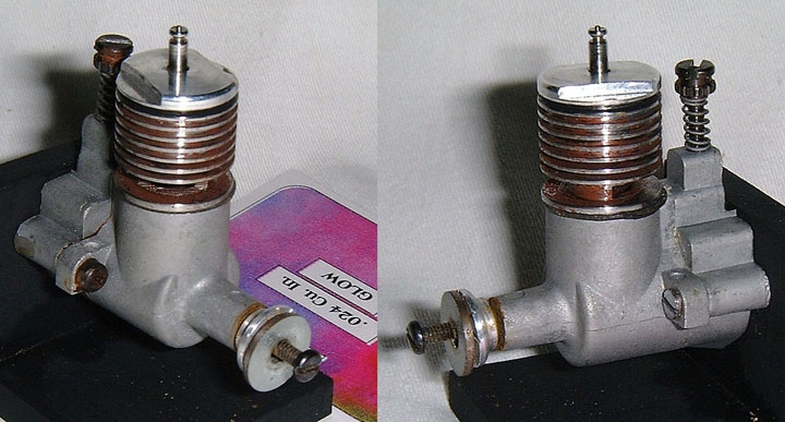
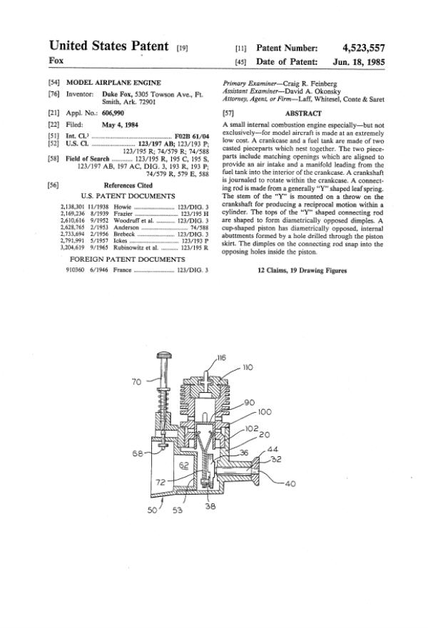
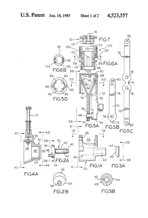
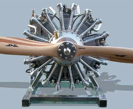
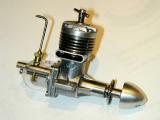
Sorry about the despicable title, but I just couldn't resist it. The engine pictured here resides in the AMA museum (picture kindly supplied by Tim Dannels, editor of The Engine Collectors' Journal) in response to a fascinating piece of engine archaeology, namely a patent, forwarded by Bert Streigler. Bert in turn had received it from another source who was researching a Fox go-cart engine and found US Patent no. 4,523,557 dated June 19, 1985 registered to the one and only Duke Fox. The pages we have are reproduced below. They are obviously not the full patent description—in fact it's hard to determine just what was new and original in the design—apart from the dinky, stamped, Y-bar conrod. The needle and spray bar are also a tad unusual, but we figure it's gotta be the conrod. The die/stripping plate that would make that gizmo with sufficient precision is beyond the bounds of even my most fevered imagination, but I'll bet Duke had it worked out.
The AMA example is, we believe, a mock-up and does not feature the Y-bar rod thingie. It never went into production as far as we know, though the case certainly looks die cast to me and the engine has a certain "Fox Rocket" flavor to it. You can click on the patent page thumb-nails below to enlarge them. Note that Figure 8 omits the actual inlet port in the casting. Patents frequently try to obscure an important operational detail while exposing the basic idea, but side-port induction is hardly what I'd call a state secret. Note also the entries under "References cited" to patents held by Anderson and Brebeck.
Pepperell Redux

Last month, I reviewed the definitive guide to Pepperell engines and put together a lamentably high-level "Engine of the Month" review of the Pep Seven-Sixteenth model. David Owen, the proud owner of the engine pictured there, has kindly parted, temporarily, with his priceless relic, allowing me to make a far closer examination. And even better, he managed to disassemble it by the judicious application of a little heat before sending it. I can't stress enough: never, never try to use brute-force to pull down an old engine—just heat it gently, 'cause if that don't unglue it, nothing else will. David's kindness has enabled me to do the full MBI CAD treatment of the engine. We are thinking about producing a die-casting of the crankcase, every bit as crude and functional as the original, although as seen last month, a fabricated case is a practical alternate. In the mean time, please revisit the Pepperell Seven-Sixteenth page for pictures of the parts and a far more detailed description of the engine—which turned out to be of very high quality indeed, considering the cottage-industry facilities they were made in.
Engine Stands

Finding a nice way to mound an engine for display permits almost infinite variation, most of them time consuming. One solution is to simply throw money at the problem. I received a nice email from Peter Scott in the UK last month heaping lavish praise on my swollen head and asking if my site accepted advertising. The short answer is no, but if the item/service in question fits within my own arbitrary guidelines of what I think regular readers would be interested in, I'm happy to pass it on. Peter's web site is under construction, and includes details of the simple stands that Miguel deRancougne used for a large part of his collection. If you'd like some of these, contact Peter. It goes without saying that I have no connection with this enterprise, and accept no responsibility for good or ill arising out of any related dealings—but Peter seems like a good guy.
New Books and Magazines This Month

While researching The Trustee from the Toolroom last month, I came across Slide Rule, the autobiography of Nevil Shute Norway, the aeronautical engineer—as distinct from Nevil Shute, the author. Norway tried earnestly to keep his two activities separate, believing that any reputation as a story-teller would not engender great confidence in his abilities to design airships and aircraft. A copy was ordered from Amazon and duly arrived, hence I am now well informed regarding the author's other career and can say that I enjoyed the book immensely.
Until reading Slide Rule, I'd been unaware that Mr Norway was one of the founders of "Airspeed", a between-the wars aircraft designer and manufacturer which I have an affection for through an early Aermodeller plan for a twin engine, rubber-powered scale model of the Airspeed Envoy designed by Howard Towner (designer of many fine, but intricate single and multi-engined rubber-powered scale models, including a B17!)
It's always pleasing when another piece of the great puzzle drops into place and the intricate mesh of *everything* becomes a little clearer. This book did that for me. Reading between the lines (and sometimes on the line) Norway gives his insights into the decisions that began and accelerated decline of Britain from major world power. Also, having been there, his observations regarding the pressures and temptations on executives of start-up companies resonated strongly. Although the book relates to happenings more than half a century in the past, it is not really "dated". Highly recommended: published by The House of Stratos, ISBN 1842322915, US$14.99.
-oOo-
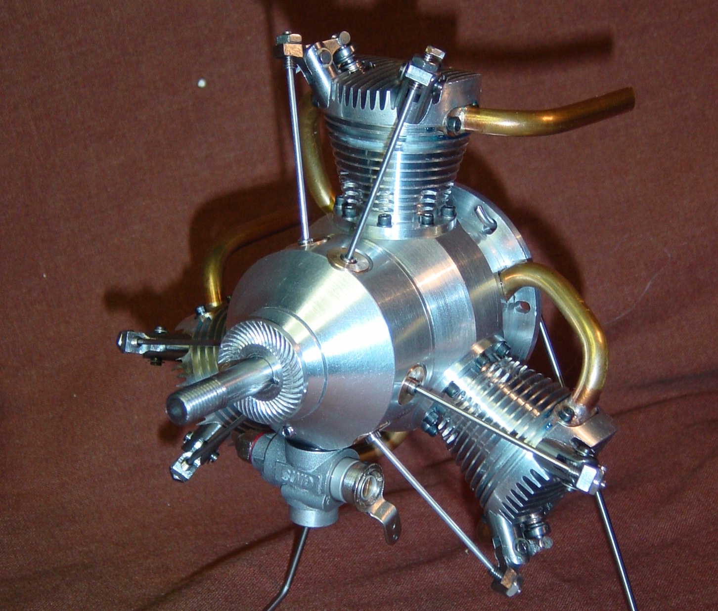
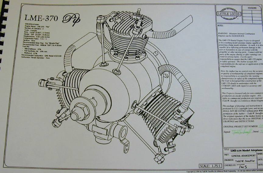
Also mentioned last month was the announcement from Todd Snouffer that he had completed his design for a three cylinder radial, based loosely on the Morton M5, and was offering plan sets for sale via the Internet. Well joy upon joy, Todd kindly sent me a set as thanks for some small help provided during the development. Now I gotta tell you (hint, hint) that I just love unsolicited graft, so this month I can give a much more informed description of the package.
The LME-370 is a three cylinder radial four-stroke with a total displacement of 0.69 cuin (11.3 cc). It uses a conventional master/slave rod configuration with a two-lobe ring-cam driven by planetary gearing. Separate rings are used for inlet and exhaust actuation. The effective stroke is 5/8" and the cylinder bores are 11/16". Each piston is fitted with two compression rings. Carburetion is provided by a readily available, commercial R/C type throttle. A diffuser running at crankshaft speed assists atomized fuel distribution to the inlet valves. The valves are turned from drill rod and are opened by rockers made from large diameter, water-hardening drill rod. The push rods are 1/16" music wire, actuated by roller-tappets. Glow-plug ignition is employed and no "sustainer" supply is required. Todd's prototype engine reportedly runs at 6,000 RPM (prop size not stated), idling at 2K on standard methanol based fuel having 15% nitro and 18% synthetic oil (minimum).
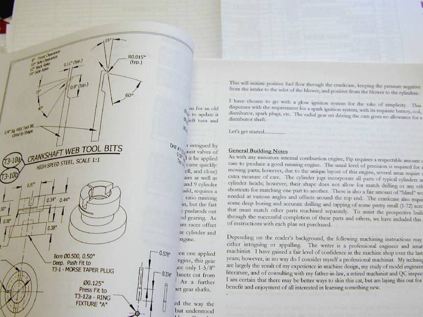
 The plans comprise 28 CAD drawing sheets, and 36 pages of instructions. They are printed on 19" x 11" sheets and arrive spiral bound and numbered (I have set #13). The drawings are clear with imperial dimensions and lots of white space. Many include an isometric rendering of the part, and even more important, they present full details of jigs, fixtures and tooling required to build the engine, including tooling to make the tooling! A parts list thoughtfully provides the material and blank size required for all parts, with a suggested supplier and their catalog item number where appropriate.
 The machining instruction pages are printed in two columns, with instructions for making the tooling presented as "side-bar" inserts. I liked Todd's description of his own instructions. In the introduction he says that builders will find them either intriguing or appalling, depending on one's background (like me, Todd is a professional engineer, and amateur machinist). I found his instructions clear, and well written for the novice builder; probably about the level I've provided on the various projects on this web site. For instance, he goes into detail on heat treating where required, with more than enough detail for the first time builder to avoid gotchas.
Of special interest to me was the George Trimble inspired piston ring heat-treat fixture. Todd's fixture is almost identical to that which I used on the Feeney rings and now believe to be wrong, despite the positive results. Todd's fixture, like my own, has the advantage of totally enclosing the ring stack, thus preventing scaling without recourse to application of extra gunk on the (exposed) outer ring surface as required by the 100% Trimble approach. Yet Todd's fixture works, as does mine. Go read the Feeney article on rings and decide for yourself.
A last word on the plans. I had not had them more than a week when Todd emailed saying a builder had noted an error on the master rod drawing and replacement pages were on the way. These duly arrived: a replacement drawing, procedure page, and parts call-out. That's very professional service for a very modestly priced package. Todd has updated the Little Locos web site since last month, adding exploded photo-rendered views of the engine. I look forward to reporting on the first plans-build example to burst into life soon.
Engine Of The Month: ED Mk I
This month, archaeology in the mountain-o-magazines has dug up the dirt on the venerable ED Mk I (aka the "Bee"). The impetus for this selection was an email from a reader requesting identification of a "watzit", that I quickly and somewhat inaccurately called an "ED" "Bee". Well, I was 50% right, but in the pursuit of engendering some degree of suspense and surprise, you'll have to go to the page in question and read the engine review all the way through to the end to find out what it's all about.
Tech Tip of the Month: Calculations with Π and desaxé
While scanning Model Engine World to locate references for the ED Bee (this month's featured engine), I rediscovered a two page article that went to great pains to complicate a simple procedure: calculating engine capacity. Pressed for time, I did not read the text in detail, so if I'm doing the original author a disservice, I apologize in advance, but one thing certainly stuck out like dog's ears, that being problems with pi.
The "capacity" quoted for our little model engines is more accurately, the "swept volume". Under what I'll call normal circumstances, this is quite simply the volume of a cylinder; in other words, the area of the cylinder multiplied by the distance the piston moves from BDC to TDC. Stated in our terms, this is the area of the bore (or piston), times the stroke. So first we need to calculate the area of a circle.
I have the advantage of a 1950's primary school education where the "times tables" and basic formulae (like the area of a circle) were beaten into us by rote—literally! In case you had a more enlightened education and lack the scar tissue that engraves that formulae in my memory, it's "pie-arr-squared" (the radius of the circle squared, times the mathematical constant provided by ratio of circumference to diameter for any circle, known since the 15th century as "pi").
For us: one-half the bore squared, times pi. Then multiply that by the stroke and you have the capacity (in most cases, but I'll come back to that).
So why did the MEW piece make such a big production over this? Possibly it IS a big deal if whatever hand-held calculator you have lying around does not have the constant "pi" hardwired. Being an engineer and scientist, nearly all mine do. But if I'm stuck, I have a couple of approximations to fall back on.
The first is "22 on 7" (more scar tissue). This gives a value that is high by 0.004%, so as a purist, I must scorn it. A far better one is 355/113. I read this one in a wonderful little out-of-print book called Asimov on Numbers, written by the famous writer of science fact and fiction, Isaac Asimov [1]. By coincidence, as I write this, an abomination of a movie usurping the title one of Asimov's most beloved fictional works is premiering world-wide. Namely, "I, Robot" and the less said about that, the better! [mumble, grumble, car chases, explosions... save me from hollywood, etc...]
A chapter in reference [1] charmingly called "A Piece of Pi", gives the history of the symbol π and its uses. The chapter is a wonderful romp, but I won't bore you with it beyond summarizing Asimov's findings on the origin of the symbol. We commonly use the Latin circumference when referring to circles, and perimeter from the Greek perimetron (meaning "around") when talking about polygons. English mathematician William Oughtred is credited with using the Greek symbol "π", called "pi", being the first letter of perimetron. It appears to have stuck. Oddly, we still refer to the "diameter" of a circle, which comes from the Greek diametron meaning "the measurement through" and symbolized as "δ" (lower case "delta") by Oughtred. Go figure.
Back to the topic. I said that bore area times stroke would be mostly correct. The case where it is not is when the axis of the crankshaft and cylinder are displaced. The displacement is called "desaxé". Contrary to popular belief, this is not the name of the French inventor! It is however French and means "unbalanced". For us, it has several effects. First, it changes the time the piston will spend on up-stroke and down-stroke from equal to skewed. Second, it reduces slightly the distance the piston will travel (stroke) from a measurement taken as twice the crankpin displacement from the crankshaft axis. Third, if the offset is in the direction of rotation, it reduces the conrod angle during the power stroke, thus reducing the side-thrust on the piston, which will reduce friction.
So if we arrange the desaxé correctly, we can get a fast power stroke with less piston side-thrust, followed by a slower compression stroke that helps transfer. Westbury was especially fond of this arrangement. I could present the math for this, but I believe that I'm running on the limit of your patience by now, so I'll demur and instead present ref [2] for the dedicated. There's a story, perhaps apocryphal, that tells of a noted engine manufacturer who had a whole production run of crankcases cast with the desaxé the wrong way 'round. Ouch.
Before closing on this topic, a quick word on units. Naturally when calculating displacement, your result will reflect the units used for bore and stroke. So imperial inches will give cubic inches. If you want cc's (cubic centimeters), you'll need to either convert bore and stroke to centimeters, or apply a conversion factor to the cuin value. All through the years that SIC was published, I shook my head in bemusement every time Bob Washburn admonished readers to convert millimeters to inches by multiplying by 0.03934—a number I doubt I could ever memorize, regardless of painful consequences. Eventually I wrote to SIC and RAW saw fit to publish that 25.4 was much easier to remember, and more accurate when used for conversions. Just divide or multiply depending on the direction. You don't even have to remember when to divide or multiply. The answer will look wrong if you get it wrong. Finally, the ccs to cuin conversion constant is 0.061. Divide by it when going from cuin to cc; multiply for the other direction.
References:
| [1] |
Asimov, Isaac: Asimov on Numbers, Doubleday, New York 1977, ISBN 0-517-371456, p73.
|
| [2] |
Blair, Gordon P: Design and Simulation of Four-Stroke Engines, Society of Automotive Engineers, Warrendale, 1999, ISBN 0-7860-0440-3, p24.
|
Westbury Kiwi
Continuing on the Edgar T Westbury theme we've been following for the past couple of months, I'm pleased to offer up some extended verbiage on ETW and the "Kiwi" four-stroke. Even better, I didn't have to research and write it. That privilege went to fellow ozzie, Phil Coleman. Phil has built a Kiwi and also has a home page dedicated to IC engines and clocks (not too sure about the temporal fetish, Phil, but good job on the IC projects). So read all about the Kiwi on the ETW Kiwi Page.
1/4 scale Wright J-5 Whirlwind

Over a year ago, in the July 2003 Editorial, I listed known scale Rolls Royce Merlin models and mentioned briefly, the plans available from Carl-Eric Carlsson in Sweden. In the past month, Carl-Eric has contributed to my sagging foundations by selling me a full set of a comparatively short-lived magazine from the early 1990's called Workshop Masters. Included in the package were some sample drawings from the Merlin plan set, and pictures of the castings for the quarter scale Wright J-5 Whirlwind nine cylinder radial designed by Karl-Erik Olsryd. The Whirlwind was the engine that powered the Spirit of St Louis across the Atlantic in 1927. The model of the engine was designed specifically to power a quarter-scale R/C model of the Spirit.
This engine was the subject of a construction series in SIC that commenced in Volume 4, No. 24 of Dec 1991/Jan 1992. You can buy plans, investment castings, bearings and gears for the J-5 from Carl-Eric, complete for 7,950 kronor (around US$1050), including postage. Incidentally, the plans included are not those that appeared in SIC, though you can save 450 kr if you already have the SIC drawings, and are prepared to chase down all the SIC revisions and errata (now slight intended, RAW was only one man doing the job of many). Individual bits for the J-5, or use in free-lance designs, are also available. For instance, a set of nine cylinder heads, with separate rocker boxes and covers cost 1,500 kr. Included is a "free" part to practice on—nice touch.
Carl-Eric's 20% scale RR Merlin plans (also a Karl-Erik Olsryd design), comprising 63 CAD sheets, are 800 kr. including postage (just over US$100 at the current exchange rate). They (naturally) employ metric dimensioning and all annotations are in Swedish. From the samples provided, it would appear practical for an experience model engineer to build the design "from the solid" with some interpolation of dimensions and contours. Drive for the twin overhead cams is by spur and idler gears, unlike the full-size engine that used bevel gears and torque tubes, or the other commercially available model that uses a toothed drive belt.
Overall, the sample Merlin plans are very professional indeed and from the photos of the J-5 investment castings, they appear to be of a very high standard. Although a grand of real dollars for the J-5 "kit" appears a steep price, consider that you get plans (40 CAD sheets and 34 machining instruction sheets), 17 castings, 12 ball and roller bearings, 10 gears (including the two internal ring gears modified to the drawings), 18 valve springs, oil seals and tubing for inlet and exhausts. Capacitor Discharge Ignition systems (CDI) for 9 and 18 cylinder radial engines are also available from the same source. To email Carl-Eric, click on the link above.

 Editorial