Editorial
Over 8,000 hits last month. The numbers just keep climbing. As I sit here, the drugs from Stage One of a root canal job done three hours ago are starting to wear off and concentration is diminishing. Which makes me ever so glad that all of this month's Model Engine News has been written bar the bit at the front where I prattle about for a paragraph or two. Perhaps this month it will be joyfully short.
We have some good stuff, and a lot of it, this month. First up, there's an absolutely brilliant coverage report of the Miguel deRancougne Auction, very kindly prepared by Ron Moulton (who must be regarded as one of aeromodeling living treasures). Then the start of the Feeney Construction series, and pics of two little somethings thrown together by two of the northern hemisphere Motor Boys in the last few weeks.
For the greater world in general, we have an announcement by Bill Gates that he (Microsoft) will "do something" about the email spam problem within two years. I'm skeptical. Our research suggests that a viable solution requires non-repudiation of source; everything else is just band-aids (or worse, a proprietary marketing ploy masquerading as a cure). Still, I'm certainly prepared to be pleasantly surprised.
On an allied topic, one of the zillions of spams I received this month was generated by the music recording industry, gleefully telling me that they'd detected an MP3 sound file on my web site and they are getting ready to sue. As an ex pro muso, I have some sympathy for artists receiving fair payment for their effort. But they've lost me now. The file in question is the sound file of Ken Croft's Delong Diesel in operation. Sweet though it may be to our ears, it's not going to take Ken to the Top of the Pops anytime soon. I have to conclude that the music recording industry is trying a scattergun fear campaign that can only do them more harm than good. In a word, the are behaving like bozos, wallies, or wankers, depending on whether you're American, English, or Aussie. Rant mode off—it's hurting my jaw.
More Red Faces
You would really think I'd have learnt by now, I mean you really, really would. Last month, to show what a really humble guy I am (hah!), I said I was going to crawl out on a limb in saying there were no alternate firing, horizontally opposed two-strokes. Well if you heard an almighty CRACK! in early January, that would be the bough breaking, so before I choke on my crow diet, I better come clean.
As mentioned in New Books and Magazines for this month, the latest bound edition of Engine Collectors Journal showed up. In it was an article from one of Europe's most respected and well informed model engine authorities, Holgar Menrad. Holgar's piece was on a little known (outside of Germany) pioneer engine designer and builder named Alexander Thusius. Well, turns out as Herr Thusius was busy proving me wrong 60 years ago by patenting a design for my "impossible" two-banger, and ECJ published a drawing from the patent to prove it.
Fortunately (for my digestion), it is still impossible for the bogus ENYA twin described last month to run. The Thusius patent used a device called a "Scotch Yoke" which allows both pistons to be rigidly joined by a straight, fixed, rod. Since the rod always remains on the (common) axis of the cylinders, it becomes possible to seal the cylinders off from each other completely using a steam locomotive-like gland nut. So now the areas below the pistons in the (sealed) cylinders can act as independent pumps. With some cunning piston porting via a single rotary valve, we can now use the crankcase as a plenum chamber to feed the alternately sucking cylinders and viola! A horizontally opposed, twin cylinder, alternate firing, two-stroke!
Holgar's article merely mentions the patent and the fact that the inventor made a model to demonstrate the concept that now resides in a museum (so is not available for disassembly and investigation).
The drawing in ECJ, taken from the patent, may be misleading—a frequent characteristic of patent drawings. What follows is my opinion on the design, with the rider that I've never seen the actual patent and little good that would do in any event, as even though my old high school results suggest I speak German better than English, I can assure you this is not the case!
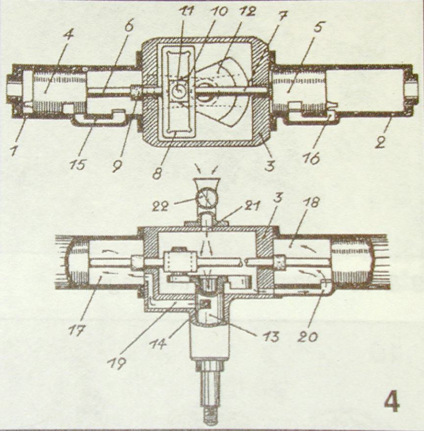
In the following paragraphs, the numbers in [square brackets] refer to the numbers on the diagram below. It may help to open the drawing in a new window as you read this.
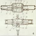 Let's consider the "Scotch Yoke" [8] first. The crankpin [11] rotates in a bearing block [10]. This block, generally made from bronze is a close sliding fit in the yoke [8], hence rotary movement of the crankshaft [12] is converted into linear motion of the conrods [6] and [7]. These are rigidly attached to the axis of the pistons [4] and [5]. Notice that the crankcase [3] seals the lower ends of the cylinders [1] and [2], and that the conrods pass through "glands" [9] to effectively seal each individual cylinder and isolate the crankcase volume from them. On each piston down-stroke, the volume under the piston will be compressed, so that at Bottom Dead Center (BDC), when the transfer port in the piston aligns with the bypass passages [15] and [16], the compressed gas will be delivered into the upper half of the cylinder, being directed at the baffle on the piston crown to produce "loop scavenging" action. The drawing does not show any exhaust ports, but normally, these would be opposite the upper bypass port and timed to open just before the bypass opens, allowing the expanded exhaust gas to escape thus lowering the upper cylinder pressure to assist the transfer.
Now the interesting, and slightly confusing bit. The lower, top view diagram shows how we can use the fact that each cylinder is totally isolated from the other to effect induction. It's confusing because the diagram shows two different schemes! Also, notice that both pistons are drawn at TDC (with the right hand conrod "broken" to show this is not a view at a single instant). Here's what I think is happening. As piston [15] rises, the pressure in the volume below it [18] decreases until just before TDC when the piston uncovers inlet port [20]. The gas in the crank case will be drawn into the right hand cylinder, drawing fresh air and fuel into the case through the inlet [21]. Notice that rotary valve [14] of the crankshaft [13] will be closed during this period, isolating the left cylinder. The right hand piston now descends on its power stroke, closing the inlet port [20], isolating the right hand cylinder again, and compressing the inducted mixture. Meanwhile, the left piston is ascending, reducing the pressure in its lower cylinder volume [17]. Sometime just before L.H. TDC, the rotary valve [14] will register with the left inlet passage [19], and the mix in the case will fill the left cylinder. As it begins its power stroke, the rotary valve closes, and the cycle begins again. We have in effect, two independent two-stroke engines sharing a common crankcase and fuel metering system. The right hand cylinder being "Piston Ported", the left being a "Front Rotary Valve" engine.
I'd be asking why? It will be difficult to assure that the inlet timing is the same for both cylinders. If they are different, the weight of the charge will be different, and so will the BMEP. I would have arranged another front rotary opening for the right hand cylinder allowing the rotary valve to do its trick twice pre rev, but then software engineers like symmetry. Then there's the "why?" in relation to an alternate firing horizontal twin. Why design an engine that's as out of balance as it's possible to get, when a simultaneous firing one is about as in-balance as its possible to get? Perhaps to achieve a power stroke every 180 degrees, or perhaps the inventor just wanted to see what could be done with Scotch Yokes. The counter balance on the front of the shaft crankweb [14] is intriguing too. This complicates the thrust bearing (omitted in the patent drawing), and what is it trying to balance? (or un-balance, more to the point) However, the concept is basically sound and an actual prototype exists—even though we don't know if it ran. Perhaps Herr Thusius just wanted to show it was possible. In any case, hats off to him.
A closing word on Scotch Yokes before you all start running to your CAD stations. The friction component is higher than a conventional connecting rod design and the as the sliding pillow block goes off center, there is a large force couple that tries to distort the piston, giving even more friction increase and potentially impacting gas seals and possibly causing lubrication break-down. So the piston has to be beefed up making the out-off balance situation even worse. Cut it any way you want, our conventional little two-strokes are as simple and efficient as we can get.
And following the Closing Word, a Footnote! A Google search on Alexander Thusius got one hit from the Deutsches Museum:
Thusius, Alexander
- ? -? (approx. 1980)
- Journalist; Commercial artist; Technical designer of Kleinstmodellmotoren
[small model engines]
- 1 box
- Correspondence and patents, exploded views, photos; technical designs partly in the plan collection
- Identification book
- German museum, archives, NL 166
THE Auction Results
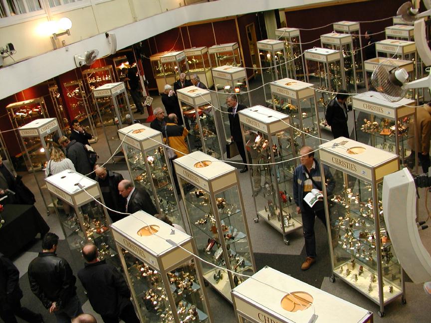
 The Christies auction of Miguel deRancougne's engine collection is over and has grossed a bit over £400,000 for his family, so far. The prices fetched for all but one of the lots are available on-line at the Christies Web Site for a while, at least. The one lot that did not sell was because the highly desirable Paul Bugl designed HP 15 team race engine it contained could not be found! But all is not lost. It appears that quite a number of engines were not catalogued by Christies and these will appear at another auction later this year. I'll let you know when I know more.
In the mean time, Aeromodelling authority Ron Moulton (who assisted with engine identification) has provided a lot of pictures taken of the auction exhibits and the action. These have been composed into a montage as a Tribute to Miguel and his passion for model engines. Use the link provided. An appropriate entry has also been added under Museums and Shows as the three day pre-auction viewing was most definitely a once in a lifetime exhibition in it's own right. While you're on the page, look at the engine in the background of the "Lot 209" photo—bless my soul, it's a Feeney!! I don't know if it is an original, or a reproduction, but it sold (Lot 208) as quote: A single cylinder spark ignition engine, with pushrod operated overhead valves with hair springs unquote, for a whopping £587.50 to some lucky buyer. Oh, the lot did include a Brown Jr, and some garden variety Enyas, plus a Super Tigre.
Feeney Construction Commences
 As mentioned last month, my reading on Helical Gear Cutting for Idiots paid off and the impediment to turning the Feeney casting kit into an actual engine has been eliminated (though whether it will be a running engine remains to be seen—there are problems). Construction has commenced, and a whole new series of pages will emerge approximately in step with the work. The link appears in the Advanced section of the Engine Construction Projects index page. Just click on Feeney. This month, we feature the "how-to" on an easy way to produce miniature helicals, and the complete words and music for the crankshaft; maybe more if I have the time to compose it.
Tech Tip of the Month: A Cautionary Tale
As if there wren't enough things to keep you from a good night's sleep. This month's Tech Tip is more in the line of a Good Workshop Practice item (and don't worry, it's not one of those gory personal injury stories). Some months back, Motor Boy Ken Croft emailed our little group to warn us about a very trying time he'd just put himself through. We all read Ken's description, made the appropriate *gulp* sounds as the implications became apparent, and publically thanked Ken for the warning and for raising our awareness of something we all vaguely know about, but had either filed in the "...it won't happen to me..." jar, or the "...must remember that..." black hole. Well, it happened to me this month, even though I've been as cautious as hell after reading Ken's tale. Fortunately, in my case, the ramifications were not serious. First, here's Ken's experience:
Hi again.
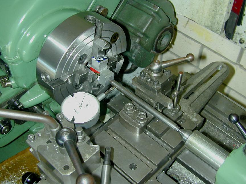
The other day I took the 3 jaw off my lathe and fitted the heavier 4 jaw. I tightened it in the normal manner, but when I started the lathe, I seemed to see the spindle or the chuck or something shoot sideways. I thought it was a bit odd, but I am always seeing odd things these days, like spiders walking about that are not there, or a mouse running about that isn't there either, so I just forgot about it. Until that is, I came to remove the 4 jaw and it would not come off. Then I realized what had happened.
The chuck had only been tight against some swarf or chippings on the mandrel, not tight at all against the shoulder on the mandrel. When the lathe kicked in at full rpm, the chuck ran into the spindle shoulder so tight that I could not undo it. I tried locking the mandrel in the usual way and put a 3 ft long bar across the jaws of the chuck, but it would not move. Only when it occurred to me to lock the spindle by engaging the back gear did I manage to get the chuck free, and that took the 3 ft long bar to do it. I talked to some old hands at the Model Engineer Exhibition, who said that this is not uncommon, and people have had to resort to unbolting the chuck from its backplate and machining the backplate away until the remains could be split away.
So beware. Don't do as I did, or it may prove a costly learning experience.
cheers
ken
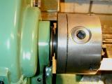
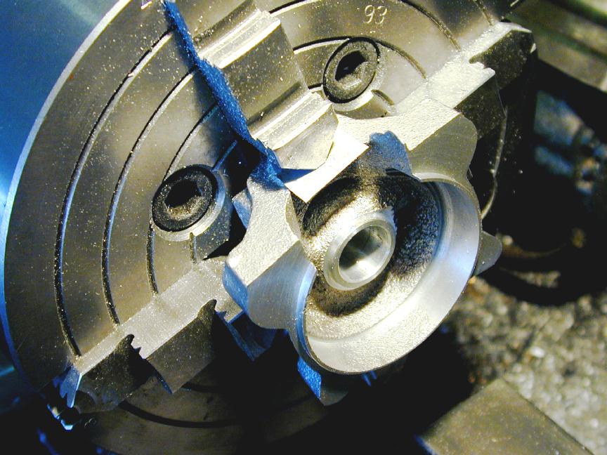
Chuck not seated |
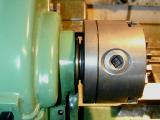
Chuck seated correctly |
The photos above show the problem and highlight the difficulty of spotting it by eye. The first photo, showing the chuck not seated against the nose register, is "posed" with the chuck unscrewed a full turn—yet it is very like the second photo where the chuck is fully seated. All it takes is a miniscule amount of swarf, and this would be much harder to spot visually. In my adventure, I happened to be looking at the chuck as I engaged the Myford's clutch and watched it spin back under inertia. It was sort of like a slow motion, life-before-you-eyes, experience. I had time for a quiet "oh blimey" (or something like that) before stopping the lathe, while realizing it was already way too late.
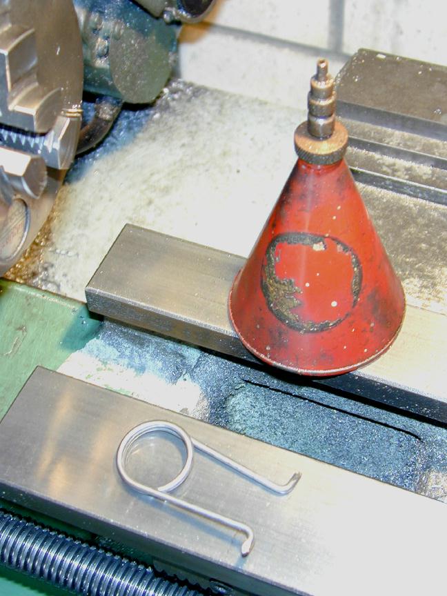
Even before reading Ken's warning, I was quite cautions when changing chucks (Note: this tale/tip is only applicable to those of us with threaded lathe headstocks; cam-lock folk have their own problems to deal with, but this won't be one of them). I keep an old tooth brush on the lathe tray and use it to remove swarf from the thread when changing chucks. I also have an old but very useful "clicker" type oil can to oil the headstock thread every time a chuck gets screwed on, and I've made a spring type backplate thread cleaner to remove swarf that gets really deep into the thread. Finally, I check by feel as the chuck screws home. If there is the slightest hesitation, it comes off and the reason is discovered before trying again. This latter is mostly to ensure the best possible concentricity from the 3-jaw, but is a good anti-swarf practice too. So how did it happen?
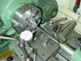
Sometimes, you can be your own worst enemy. My near downfall came about not through swarf, but cleanliness! I'd done all the above and the 4-jaw independent chuck spun on silky smooth. Next step was to setup the job to run true using a DTI and a wobbler. While doing this, the chuck is rotated back and forth by hand. It was while doing this that my silky smooth thread was undone, un-noticed, by me! The gap was small, but enough to notice the chuck leap back onto the register when power was applied. I was saved by the low speed and the chuck came loose with normal effort under its own inertia. I use all HSS tooling (having built that bloody Quorn to sharpen HSS tooling, I intend to use it!) Ken uses insert technology, so he seldom engages the lower Myford speeds via the second belt, while I seldom engage the upper ones. So, saved by lack of technical progress on my part!
So now I've found Yet Another of the myriad things that are just waiting to go wrong and have added the precaution of removing tension from the Myford multy-step drive belt to the check-list used while playing with the wobbler. This frees up the headstock spindle, minimizing the chance of inadvertently unscrewing the chuck. As a footnote to the tale, after validating that chuck and spindle were still separable, and realizing that the 4-jaw may not have been hard against the headstock spindle register, I decided it would be a good idea to re-check the setup. It was a good 10 thou out due to final adjustments having been made with an unregistered chuck (so to speak  ). Now don't say you haven't been warned...
New Books and Magazines This Month
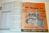 There are three ways to buy Engine Collectors' Journal. First, you can subscribe. Each subscription is for six issues which appear when and as editor Tim Dannels has the material to fill them. Second, you can order single copies from The Model Museum, going all the way back to Volume 2 (there effectively is no Volume 1). And lastly, you can wait until a volume is complete and get it in soft cover bound format. I prefer the latter, and even though it means I may have to wait a year or more to see what my friends and others have been up to, I believe the wait is worth it. Now the good news is that Tim has just released volume #28, comprising issues #157 (April 2003) through #162 (December 2003) and it arrived in my mailbox last month. This volume contains the landmark 40th Anniversary Issue and Tim must have been thinking of me then he chose a twin as the cover subject for the month
Highlights of this volume include Roger Schroeder's adventures restoring an Atom (manufacturing would be closer to reality!), the start of a very complete and well researched series on Fox engines from go to current, pictures of two actual Feeneys, some great articles on very rare and unusual motors, and the Holdar Menrad piece that has impacted cuisine at my place in recent days (see this month's True Confession). All this for US$25. Great work Tim, and thanks to all who freely contribute their time and effort for the enjoyment of others.
Engine Of The Month: Den Allen's AE Range
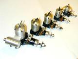 This month we feature Dennis Allen's AE range of bar-stock diesels. These appeared on the market in the 1990's, and range from a miniature 0.1cc (0.006 cuin—just multiply by 0.061 for a close-enough conversion), to a 2.5cc, twin ball race, Schnuerle ported design. You can read the story by clicking on the thumb-nail, or by looking them up in the Engine Finder.
Rear Rotor Madness: The Answers, Really!
Having stretched this one out beyond a joke, listed below are the answers to the question. If you want to know the questions to the answer, go re-read November 2003 and January 2004 Model Engine News columns.
- DC Rapier 2.49
- ETA 15
- Webra 15 "Bully"
- Dooling .29
- McCoy .60
- Frog 3.49cc
- ED Hornet 1.49cc
- ED Racer 2,49cc
- ED Hunter 3.49cc
- Ivor F "Sesqui" (1.5cc obviously )
A Very Rare Brit
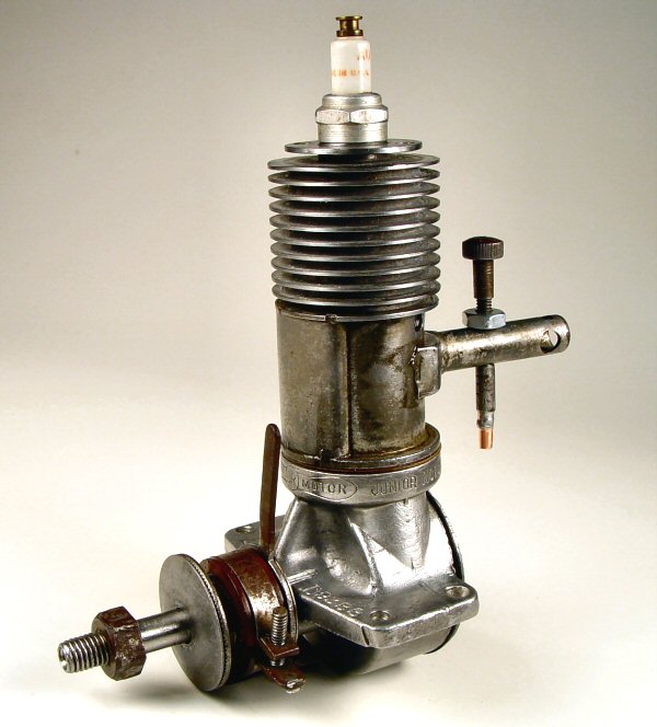
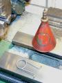
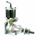 This unusual little side-port is the MS 1.2 and no prizes for intuiting that is is a 1.2cc (0.073 cuin) "diesel". It was manufactured and sold through The Model Shop Newcastle (the UK one, not Oz ), which explains the "MS" part. It appeared in the post-war 1940's along with an even rarer 2.4cc engine with compression adjustment via an eccentric crankshaft bearing. The engine pictured here is an original and after being measured and dissected by Motor Boy Ken Croft, sold for a princely £300 at a swap meet. A week later another original sold for £450 at the Gildings auction. So Ken quite correctly decided he'd better get on with making his copy.
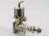
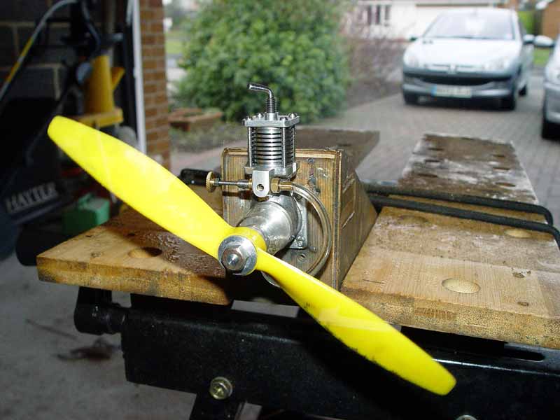
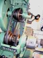
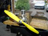 The reproduction is now complete and you'll have to agree, it's a beauty. As a group, The Motor Boys try to be ethical about our reproductions—we don't make them for sale, nor do we part with them, so there is little likelihood of their appearing in less scrupulous hands, being offered as the Real Thing. The tell-tales on Ken's MS 1.2 are: a sand-cast case (original appears die cast), less taper on the front of the fuel tank, and round-head screws as opposed to cheese-heads on the original. The picture captured on the test stand shows the engine running, but as usual, the prop has been strobed into stillness by the flash. I'm busily CADing the engine now, so it will be a future Motor Boy plan.
A Very Rare Brown
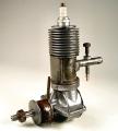 You are looking at the exceedingly rare Brown SB1. In fact, Bert Streigler confidently states this is the only one in existance—having been made from his Scrap Box (hence, "SB1"). During the past month, we exchanged mail on another unpopular motor making aspect, namely, making counter-balances cut-outs in crankshaft webs (a future Tech Tip Topic). Bert dug out a shaft to illustrate his Texas Rancher approach to the problem, and realized he had enough bits to complete a flyable Brown lying around:
This is a rare model Brown - there is none other quite like it. OK, so I am pulling your leg! After I took the pic of the shaft to show my set up for machining the web balances, I realized the shaft was one of Don's built-up Brown cranks. So, I went to work and finished the machining of the web. Then it occurred to me that I had some other Brown parts, mostly junk, so I drug this stuff out. I had a cylinder from a model C where the needle valve hole was near the end of the intake. Then some idiot drilled two holes and probably tried to fit it with a choke nut, but then realized that it was always open somewhere because of the extra holes. It did not matter because he took a big pair of pliers to the cylinder to remove it from the case and distorted the cylinder, in addition to leaving the fins in pretty horrible shape. So, I drove a steel bar down into the cylinder. The bar was machined to the bore but with about .002 clearance and generously coated with grease and graphite. Most of the distortion was in the exhaust port area and the bar straightened it out pretty well. Then I honed the cylinder with a brake cylinder hone - very crude - and then lapped it, made a piston and fitted it. Believe it or not, the silly thing has super good compression. I had a junk Hurleman timer that fitted and by day's end I have a Brown that should make a good runner. I will put a sleeve over the inlet tube to tidy it up. Just to make matters worse, the whole mess is assembled on a late model D case and it has a model B connecting rod.
The monster came to life, snarling and smoking from it's nostrils. Actually, the thing runs quite well, but it will take a long break in. After about 6 tanks (Ken, the tank is one of the funny little film canisters you sent me), the engine will start reliably on the first flip! The procedure is to give it three chokes, turn on the ignition and flip hard - and away she goes! The piston/cylinder fit worked out really good, with good, hard compression and just a little pinch near TDC.
I always liked the old Browns because they were very reliable and are surprisingly good runners. Most of the parts for this one are 1938 vintage aside from the home built stuff. The first two tanks were on FAI fuel, but the last two were on gasoline and 70W oil with its delicious and distinctive smell. Oddly, this engine runs better on the gas and oil mix than it does on the alky and castor mix.
So, there you have it, an original Brown SB 1 (Scrap Box 1). Better than nothing, I guess, and I now have one I can fly without worry.
Bert.
The technique Bert used to repair the butchered cylinder is quite smart, and similar to a technique I've read about called "ball sizing" where a hardened, precision ball is forced through a hole a thou or so smaller than the ball to make it a uniform, circular size. Since the Brown cylinder is blind, this was out of the question, so Bert's done the next best thing. Now, the Motor Boys are a pretty blasé lot, so while we may have ho-humm'ed over the Brown (
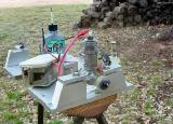
jolly good show etc ), we went into absolute raptures over Bert's test stand. Look at that thing! Fully adjustable, rock solid and double-ended. Now that's a real test stand...
Coming Next Month
More Feeney construction, the Allbon Javalin, and making counter-balance cut-outs in crankshaft webs, what else?!
 More Red Faces
 Editorial