Editorial
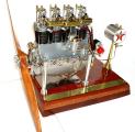 Welcome to 2004—meaning it's now 20 years since 1984 and the sky has not fallen. Or perhaps it has, but we've been conditioned not to notice. Sure been hot enough here to make me think I'm living under a pile of steaming rubble. The Seasons' Greetings picture here was provided by prolific builder and craftsman, Les Stone. It's a DeHavilland Gypsy 1, the engine that powered the Gypsy Moth. The model is fully operational in 1/4 scale and you can click on the pic for more details.
I'd hoped to see the hit counter climb past the 100K mark for this posting, but alas, it's just a gnat's wisker short at 99,515 and gives 7,238 hits for the month. Still, this page was posted 2 days early (December 30 Downunder), so not bad considering the amount of math I inflicted on the world last month. But the outcome of that math (and corresponding research) is a 30 degree, 40 DP, 20 tooth skew gear for the Feeney (see Coming Next Month in this issue), so it's all been worth while and I know what I'm going to write about next month  .
.
For no particular reason, here's some metrics on this site at the approximate date of this page's posting: The twisty little maze of passages from the home page contains 222 separate HTML pages, and 3515 JPG images. Of these images, 1438 are thumbnails, so the actual picture count is 2077. The HTML pages contain a total of 293,264 words for an average of 1,321 per page (including HTML page formatting directives). Due to the less than wonderful way the pages are linked and indexed, the only way to see them all is via the links in the left-hand frame of where you are now. If you don't see this frame, you've entered through a side door and should go the the real front page as given in the Standard Stuff section of this page.
Auction Pending: Christie's
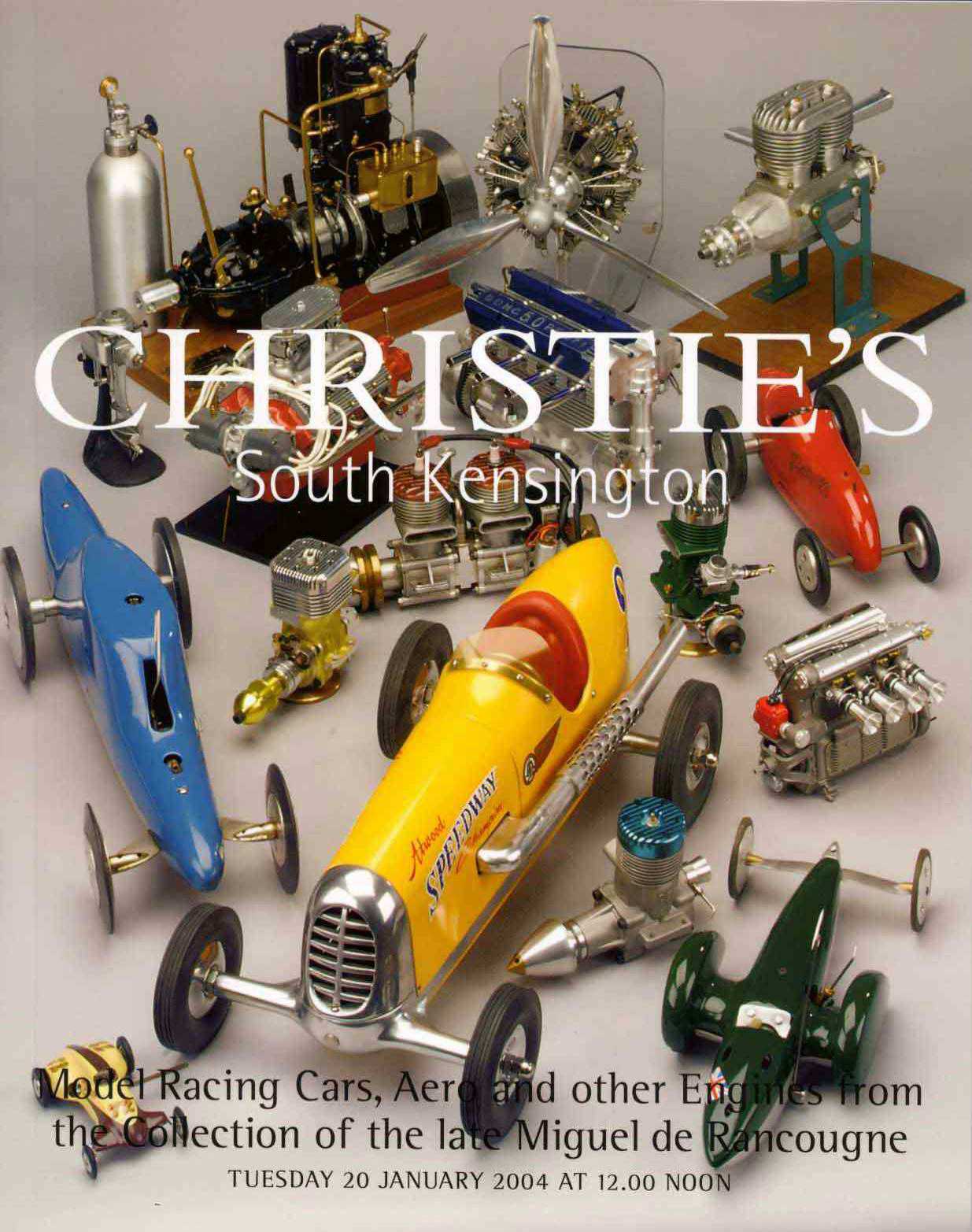
 The October Issue of Model Engine News reported that the Manuel de Racougne collection would be auctioned by Christie's on January 20, 2004. The catalogue for that auction is now available for purchase. The collection, amounting to around 1200 items, has been sorted into "lots", so prospective bidders will potentially have to bid on several items they don't want in order to get the one they do—then dispose of the remainder (I expect Feb/March will be a hot time on eBay). Although being conducted in South Kensington, the auction will be "live" in the USA over large screen TV. If you don't want to shell out for the catalogue (which will still be available for sale for some time after the auction I'm told), here's the link to the on-line catalogue, all 20 pages of it. If your only experience with auctions is eBay, or "trash 'n treasure" events at the NATS, be sure to read the fine print on how the Big Boys play this game. A "premium" of 17.5% (plus VAT or sales tax) will be added to the hammer price for each lot. Afraid I won't be partaking—still it's nice to see that the "M14" made it to the front page of the catalogue.
Auction Results: Gilding's
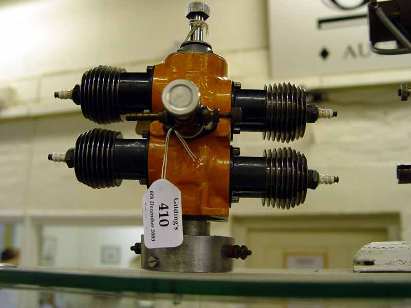
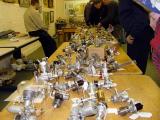 And while on the Big Boys Auctions topic, the Gilding's Fifth Annual Vintage and Classic Modern (sic) Engine Auction mentioned in the October issue was held on December 6. It proved a disappointment to some (though not to all, especially the new owner of the Elfin 50). Ken Croft, who attended to bid on behalf of a couple of the Motor Boys for things that had taken our fancy, provides the photographs and material for the report here.
 In the event, we were unsuccessful and in a number of cases, Ken decided not to bid at all as the condition of the item when seen in the flesh was so disappointing (Now I ask you, what kind of person would drill a hole in the side of an ED Miles Special? Perhaps a pressure tap point, but still butchery). Anyway, Ken says:
There were a couple of total surprises on the day. A Milford Mite, probably the worst diesel engine ever made in England that should have been worth a max of £150 just for its rarity value went for a massive £590 (US$1027, A$1390), followed by a standing ovation! The second surprise was an Elfin 50 that was expected to go for about £300 to £400 (say US$500-700, or A$700-950), but the estimate was only £50 to £80. A couple of bidders were messing about in £5 increments at around £50 to £60 and suddenly the hammer came down at £65 because he thought the bidding had stopped. Simultaneously about 10 bidders shot their hands up, me included, but the hammer was down and the sale was confirmed amid a general hue and cry that the auctioneer was just far too quick. Had the estimate been more sensible I am sure he would have let it run, but there it was, a mistake and a real bargain for the bidder.
 Top price paid was £1700 (US$2950, A$4000) for a Fergurson Condor four cylinder two-stroke. This is an engine with a history. During The War (that's WW II, da Big One, sonny ), Mr DA Russell, managing editor of Aeromodeller magazine in the UK, began construction of a large scale model of the Westland Lysander. Intended initially as a free flight model, it received wide coverage, appearing in various stages of construction at exhibitions, in Aeromodeller and other publications. I've seen photographs of the model with an Elf "Goose-Egg 4" and the Condor bolted on. Ultimately, in 1950, LH Sparey designed and built a monster 47cc single cylinder two-stroke especially for it (the engine appeared as a construction series in Russell's Model Mechanic magazine, then edited by LHS—DHR certainly knew how to extract maximum value!) As far as I'm aware, the model was never flown. Exhibiting a certain degree of optimism, the Gilding's catalogue suggested a value of £2000-2200 for this engine. Lowest price at the auction was £6 for a Jet-X 50 carrying an estimated price of £10-12. For comparison, the "premium" for room bidders was 12.5%, while Internet bidders paid an extra 17.5% (before tax).
The catalogue is viewable on line (for a while longer, at least) at http://www.gildings.co.uk/pdfs/Cat061203.pdf.
All That Glitters May Not Be ENYA
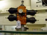
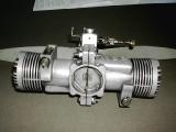
 Here's an intriguing picture sent in by a reader of an unusual ENYA that's come into his collection. The story that accompanied it suggested that it was one of only 600 made by the factory. My reader reports that the pistons are arranged to fire every 180 degrees, making it an alternating "boxer". Oh dear. Now picture Ron, checking his balance carefully as he prepares to crawl out on a limb, far above the ground. Sorry, but I 'gotta call Bravo Sierra on this one.
Some time back, in the October 2002 Editorial I had to confess to being completely wrong about how to "time" a Saito FS-80T boxer twin 4-stroke. I'd made the grand but erroneous assumption that ALL opposed twins would be simultaneous firing—as this results in a smooth running engine with the reciprocating masses trying hard to cancel each other out. Well what could I say but something like "MmmMmmm... this crow tastes mighty good." Before the month was out I'd discovered that Saito did make alternate firing, opposed twins, and no less an authority than Peter Chinn reported that it didn't shake as bad as one would expect. So why am I crying foul on the ENYA?
Because it's a two-stroke. The humble two-stroke depends on crankcase volume varying as the piston goes up and down to act as a pump that will draw in mixture on the up-stroke, then force it under pressure into the cylinder on the down-stroke. This forces out the remnant of the previous burnt charge (scavenging), readying it for the next compression and power stroke. If there's one piston going up as another is coming down, the net result will be close enough to a constant volume, so the crankcase will neither draw in mixture, nor transfer anything anywhere.
Now look at the inlet. It's a standard Enya front-end, rotated 90 degrees to give a pleasing appearance. An alternate firing two-stroke would require this front rotary valve to be drawing in two charges per rev. I won't even bother trying to describe why that won't work—it's just too silly for words. And look at the rotating exhaust restrictors on the cylinders that are flapping in the breeze. Originally, the restrictor was connected to the carburetor arm to improve the low speed idle by increasing backpressure (a common enough practice before mufflers made the scheme impractical and unnecessary). The fact that they have been left unconnected suggests that the builder never intended this contraption to run. The hardware store bolts and pressed steel nuts holding the case together are a bit agricultural too, and let's not go too close to the backplate seal and the fact that there's no practical way to mount the engine—and a 1.2 cuin engine that has been designed to run as out of balance as it possibly can is going to need serious mounting!
We've not seen the internals, but consider what the con rod arrangement must be like. The people at Enya design and make good engines—like the 90 degree V twin cylinder four-stroke pictured here, so the crankcase volume in that single cylinder 60 would be just what is needed by a single cylinder 60; no more. When you try to fit two con rods onto a single pin, the width at the big end is going to have to be reduced to 1/2 of what is really needed. "V" configurations with the cylinder centerlines lying on a common plane at right angles to the crankshaft would probably use a "fork and blade" big end, or a "master/slave" rod arrangement similar to radials. Four cylinder four-stroke boxers (Lycoming, Continental, VW, etcetra) stagger the cylinders so that the pairs of rods can sit side-by-side, but still be on the axis of the respective cylinder bore. The model two and four cylinder two-strokes made by Ross put the cylinders in line and accepted that the rods would be offset fore-aft from the cylinder center-line. Not ideal, but it certainly worked well enough.
Back to the monster. We have no real idea of the origin of this creation. It's even quite possible that the builder made it as a joke from two run-out engines, with no intention that anyone would ever take it seriously. But somehow, it has moved into the rare collectable arena where it can do nothing but leave a bad taste in people's mouths. What's even sadder is it could be made to work! Here are the major problems that need to be addressed (as I see them):
- Crankcase modification and joining
- Configuration/design
- Crankshaft and con rods
- Engine mounting
Crankcase modification and joining
 The basic idea of using the old mounting lugs as flanges to join the cases is sound enough, but we can make it much better. First, fit a pair of close fitting dowel pins between the old engine mounting holes to key the case halves into assured alignment, and fit some decent cap-head machine screws and nylock nuts. Join them so both exhausts point in the same direction. We can do this because next we mount the case up on the lathe and bore right thru to get a nice straight, circular and true bore. The front and rear case faces are skimmed at the same time. Then we machine new front and rear bearing housings to be a close fits in the case bore. This will further assist in keeping the case halves in alignment as the case has to be opened for assembly.
Configuration/Design
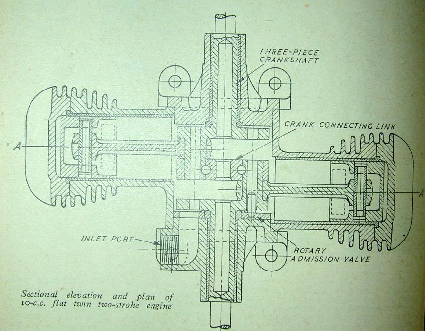
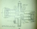 To stand any chance of running as a twin two-stroke, it has to be able to pump, so it must be made to fire simultaneously. This means we need a two-throw crankshaft. The picture here shows the internals of Edgar T Westbury's Craftsman Twin of 1948. Notice the "stagger" of the cylinder axis ETW needed to match crank and cylinder geometry. He also chose to use a fabricated crankshaft, allowing the connecting rods to be one-piece items. The crank joining piece is slit in the center to allow the hi-tensile bolts to clamp it to the crankpins, as well as keying into the pins. This required a substantial connecting link, but as he was designing from scratch, he was able to adjust the cylinder stagger accordingly.
Crankshaft and Con Rods
We have no such luxury. The cylinders must be in line, so the crank throw joining piece will have to be as thin as possible. The G-Mark boxer twins used an overhung, two piece, double throw crank. The rear piece was a disk with two opposed crankpins on either side of it. The front pin was longer than the rear and was secured into the main crankweb (after the rod was slipped on) by an ingenious tapered clamp arrangement. There was no rear shaft, so the rear rod just slipped on normally. Bert Striegler pointed out to me that the forces on the two crankpins will tend to cancel each other out—provided both cylinders are either firing equally, or not—so it's not as bad as it seems—although there will be a twisting couple. Bert has owned and run both the G-Mark opposed twins and likes them a lot (there was a little one and a big one—the "big" still one being only 0.30 cuin, I think).
 The excellent .30 cuin G-Mark aside, I'd feel safer with a "full" crankshaft, supported in ball races at both ends. This means that the con rod big ends will have to be "split" to use caps, or straps. Fitting the rods into the available space will be a squeeze and we may have to go to split bushed steel to get sufficient strength. The throw has to stay the same or we screw the timing. As the big ends will be split, or "strapped" (like a Calkin Elf, or Westbury Ladybird), clearance will be a problem too. We can probably reclaim some of the room by reducing the thickness of the front shaft web from that of the standard crank web since it no longer needs to double as a counter weight. But this could still be a show-stopper, so careful layout work required beforehand (CAD to the rescue). Front or rear rotary valve boxer two-stroke twins can easily suffer from having one pot run leaner than the other. The Bantam (pictured here) solved this by having both front and rear rotary valves. I'd be tempted to just go for a front rotary since the cylinders are in line axially, and hence there's no "rear" pot as such.
Engine Mounting
No problem. This whole scheme will work because of the nice little lugs cast into the rear of the ENYA case. These allow us to "reverse" the cylinders and have close fitting spigots on the (new) front and rear case covers. These covers carry the bearings for the "full" shaft, and the rear one can be machined to provide bulkhead mounting ears (or M5 like mounting ears if we feel like brazing up a "full-size" style space-frame mount). The old mounting lugs can be reduced in width a bit and blended to make them stand out less.
I love twins. But they are a *lot* of work to make and at model engine sizes, will never perform as well as a single of the same capacity. The hypothetical we've just built will be weak in the conrod department. The induction may be inadequate to feed both hungry pots cleanly. The crankshaft will probably have a too-light center web in order to compromise on the rod offsets in their cylinder bores. So no matter how you cut it, we end up with a delicate curiosity that's probably not worth the effort it took to make it. Would still look (and sound!) neat though.
Tech Tip of the Month
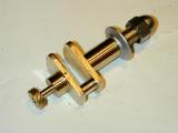 Crankshafts for single cylinder engines fall into two categories generally called "full-throw", or "overhung". The overhung variety is the sort we are accustomed to seeing in model engines. The other type, shown in the picture here, is what we'd expect to see in our lawn-mower (or motor-cycle, or maybe our weed-eater, or giant R/C accident waiting to happen). The purpose of a motor is to produce power, and the enemy of power is friction. We take great care to machine the crank-pin of an overhung crank to be axially in line with the crankshaft. But when running, it is seldom in that position as pressure will be bending the crank web one way, then the other. This constant loss of axial alignment between the big and little ends of the conrod increases the friction and wear, especially on the the big end of the connecting rod (which is generally a softer material than the crank pin). As a full-throw crank is supported at both ends, the pin cannot deflect, but now we have more bearing area to worry about (and extra complexity in the crankcase manufacture).
The "full-throw" crankshaft is not encountered much in simple, single cylinder model engines. While it will prevent deflection of the crank pin, it's needlessly heavy and complicated to make. Still, since I'm scratching for a tech-tip and have just machined one, here's a little trick learnt from reading old issues of Model Engineer about how to machine crank shafts for steam engines—or at least looking at the pictures anyway.
Crankshafts for single cylinder engines fall into two categories generally called "full-throw", or "overhung". The overhung variety is the sort we are accustomed to seeing in model engines. The other type, shown in the picture here, is what we'd expect to see in our lawn-mower (or motor-cycle, or maybe our weed-eater, or giant R/C accident waiting to happen). The purpose of a motor is to produce power, and the enemy of power is friction. We take great care to machine the crank-pin of an overhung crank to be axially in line with the crankshaft. But when running, it is seldom in that position as pressure will be bending the crank web one way, then the other. This constant loss of axial alignment between the big and little ends of the conrod increases the friction and wear, especially on the the big end of the connecting rod (which is generally a softer material than the crank pin). As a full-throw crank is supported at both ends, the pin cannot deflect, but now we have more bearing area to worry about (and extra complexity in the crankcase manufacture).
The "full-throw" crankshaft is not encountered much in simple, single cylinder model engines. While it will prevent deflection of the crank pin, it's needlessly heavy and complicated to make. Still, since I'm scratching for a tech-tip and have just machined one, here's a little trick learnt from reading old issues of Model Engineer about how to machine crank shafts for steam engines—or at least looking at the pictures anyway.
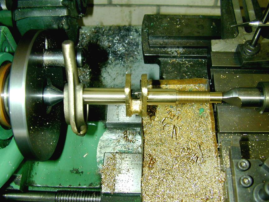
Our subject here is the "Feeney" four-stroke. If you've been reading these pages for the past three months, you could be excused for thinking I'm getting a bit obsessive about this thing. This fixation has largely come about through the need to make a skew gear if the engine is ever to be built. Having explored possible ways to do this, I decided that to test the gear, the crankshaft and case would have to be made. So first step: machine the shaft. Art DeKalb's kit contains a giant lump of cast bronze that duplicates the original. Machining the crank throw will require the shaft be offset from it's axis in a special jig, so the shaft must be machined first.
The best and easiest way to do this is between centers. First, centers are marked on each end of the casting using a surface plate and marking block. Each end is then center drilled after making the marked ends run true in the 4 jaw chuck. There is another way using a vertical slide in the lathe, but it's more effort than using the 4-jaw.
 Now, finally, the tip: we have to prevent the centers from springing the casting together in the gap. This would result in a shaft that is not straight when the pressure is removed. To prevent this, we fashion a short screw-jack from a piece of 8-32 bolt cut just shorter than the gap. Nuts are screwed onto each end so that they can be unscrewed to make the thing a firm fit in the gap (the inner faces having been dressed flat with a file first). Obviously we must not over-tighten the nuts or we'll be causing the same problem we are trying to prevent! The gizmo is jiggled into somewhere close to the phantom axis of the shaft in the gap and brought to finger tight. A light tweak of the spanner makes it firm without turning it into a jack. The lathe centers can now be brought to bear and heavy cuts applied with impunity.
New Books and Magazines This Month
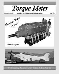
 Yup. Got a few. First up, the last issue for 2003 of the Aviation Engine Historical Society journal Torque Meter. A good, well researched piece on Menasco and his engines, more on "hollow shafted" constant speed props, and way more that I really wanted on Reno racers. AEHS has maintained their publishing schedule and is not taking subscriptions for 2004. I'm 50/50 on renewing. There's been some good material, but I'm left with the feeling that if I did a page count, the number of pages devoted to unlimited racers at Reno would be way outa proportion.
 Next up we have Internal Fire by C. Lyle Cummins Jr, Carnot Press, Wilsonville OR, 2000, ISBN 0-917308-05-0. No prizes for guessing that that this is a book about Internal Combustion, although the title is rather clever in they way it manages to convey the topic and theme—that being the history of the development of internal combustion engines 1673-1900, and the "fire" that burned brightly in the hearts and minds of those who contributed to its development. And if the author's name seems familiar, that would be because he is the son Clessie Lyle Cummins, the man who founded the diesel engine company that bears his name.
Amazon reports that the book is currently out of print. There have been two imprints (1976 and 2000) by Carnot Press, and one (1988) by the Society of Automotive Engineers. I had no great difficulty locating a New In Box 2000 edition (this is a quality book) after a short web search. In 355 pages and 14 chapters of clearly written text, liberally illustrated with reproductions of early drawings and glossy photographic plates, Cummins traces the development of internal combustion, placing each step within the cultural context that drove it. You'd have to call this a "scholarly" work as each chapter is meticulously referenced with end notes, but I found that the entertainment value was in no way diminished by this.
Of necessity, the author must first trace the development of external combustion engines (steam and "Stirling") and the patent system operating within Great Britain, the USA, and Europe as these had a significant impact on inventors and their inventions. He then proceeds through the inventors who missed the concept of compression, yet still produced commercially viable internal combustion engines. Next is the four-stroke cycle (and who should be credited with it); the two-stroke, and finally, in a chapter titled "Rudolf Diesel: the End of the Beginning", compression ignition engines.
This is not a light read. The many drawings illustrate complex machines and the text provides just enough description to plumb their operation (mostly), even if you back-and-forth a few times. This is not a criticism. To cover the breadth of material he does without bogging down in needless detail is an achievement. Frequently, he is trying to explain the operation of a mechanism from a patent drawing—which not uncommonly were prepared in such a way as to obfuscate the operation they were intended to protect! Cummins also provides some insights worthy of note—such as the gunpowder cannon as an engine—certainly the ultimate in long stroke? I expect the public library system should be able to obtain a copy for you on inter-library loan, and most university engineering libraries would most likely have a copy. I'd also guess that the book was initially self-published. The author's acknowledgments are post stamped "Wilsonville, Oregon" and the name "Carnot Press" is a dead give-away, especially as Cummins opens the book with a quote from Sadi Carnot on heat engines (1824). Recommended to serious students of engines and their history.
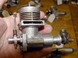
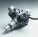
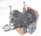
Engine Of The Month: DC Manxman
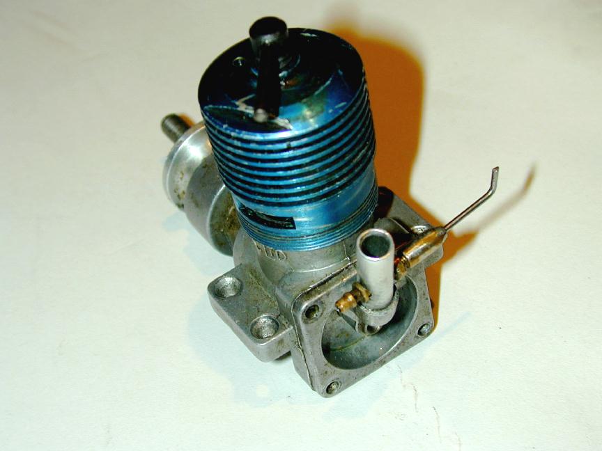
 This month's featured engine is the Davis-Charlton Manxman of 1956. Last month I added a single picture of this engine to the Engine Finder. That has now been expanded into a full review, complete with archival research, together with my usual fanciful and unfounded speculations. The engine pictured here came into my collection last month in trade for an AHC. At 3.5 cc, it's a big brute that the DC add in the March 1956 Aeromodeller calls "A real man's motor". The Manxman was released soon after DC's move to the Isle of Man, replacing the earlier DC 350 which it resembles. Click on the pic to access the review direct.
Bruce Engineering On-line
Last month I mentioned Bruce Engineering as the source of the kit for the little hone-clone I use for pistons and shafts. All I ahd was a snail mail address dating way back. Well thanks are due to Mike Waters who emailed me to say the Bruce Engineering appears to have been taken over by a manufacturer of live steam locomotives and kits named "Polly Model Engineering". They have a web presence at http://www.pollymodelengineering.co.uk and can be emailed at [email protected]. Their web site makes no mention of the little hone kit, so I suggest dropping them an email.
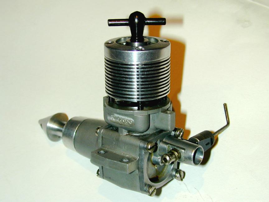
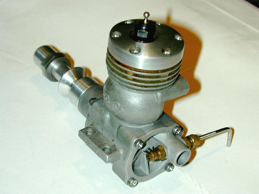
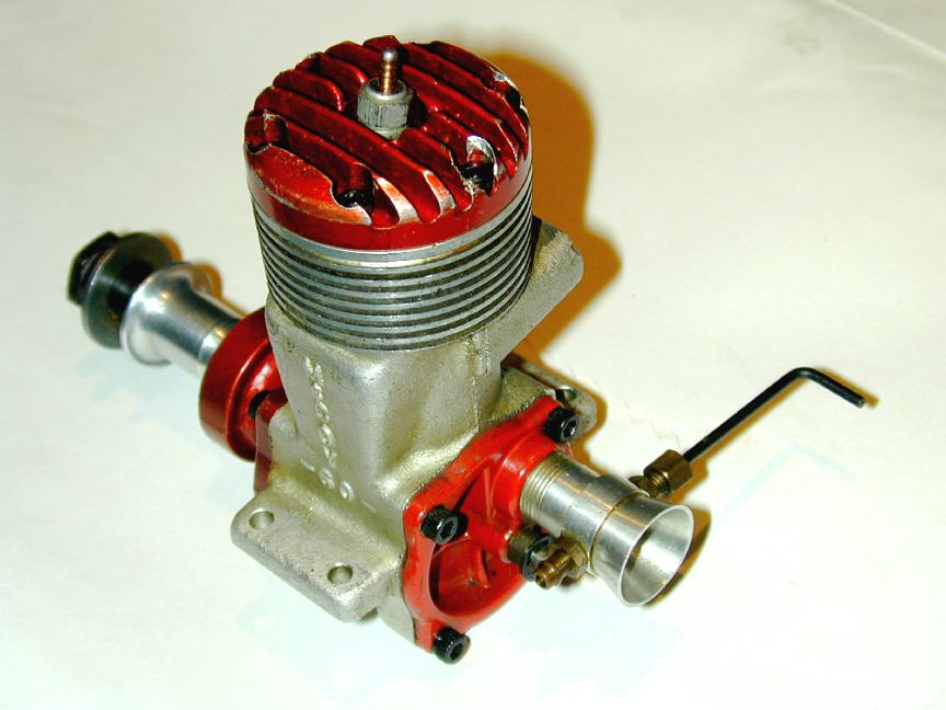
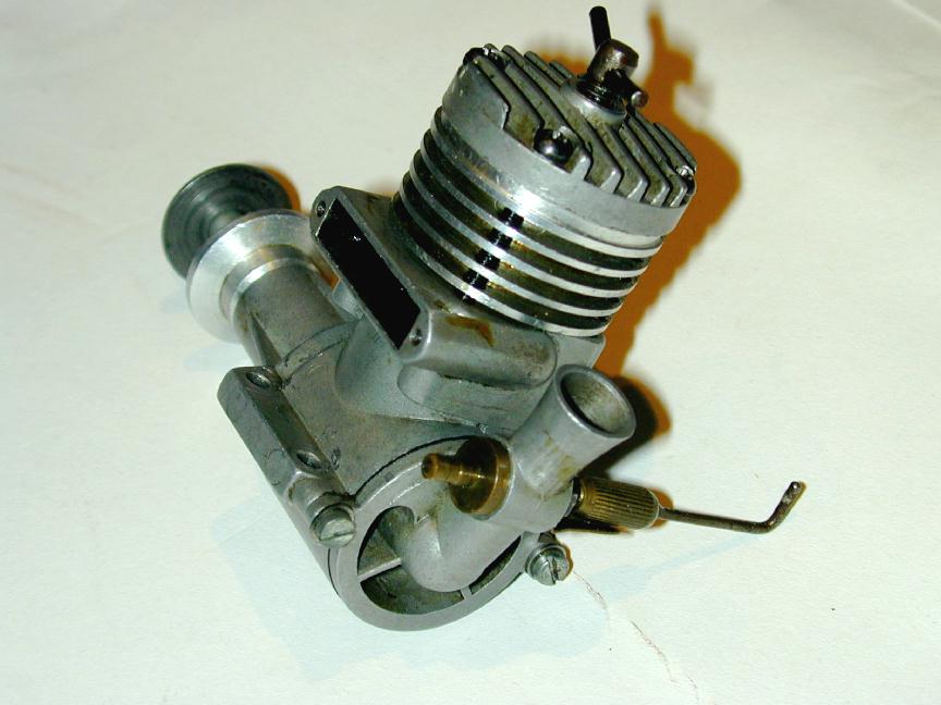
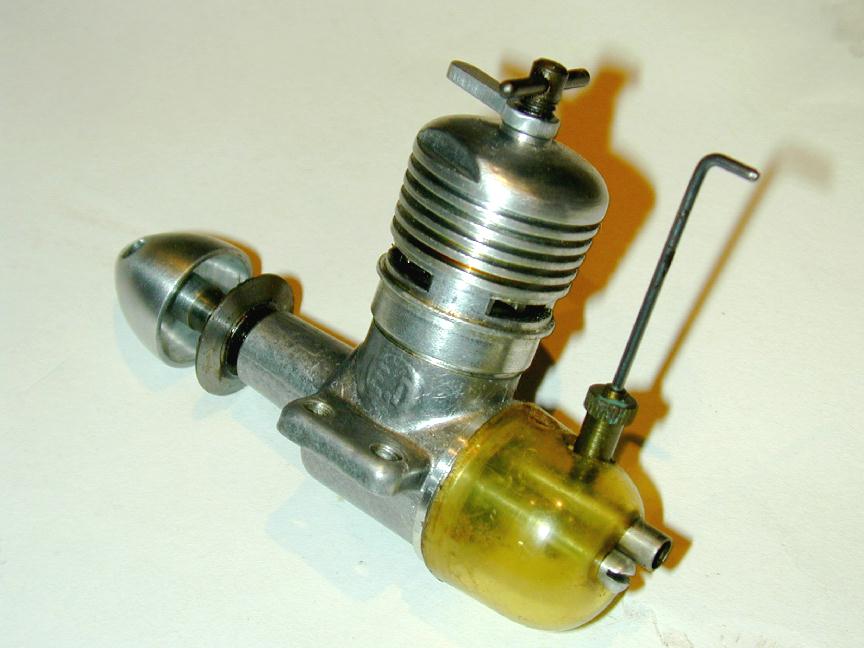
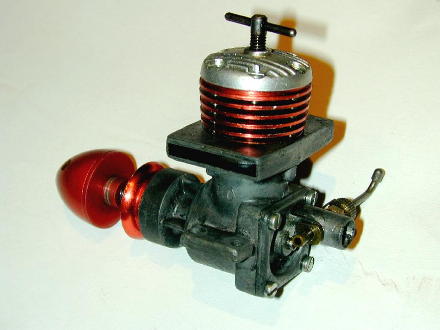
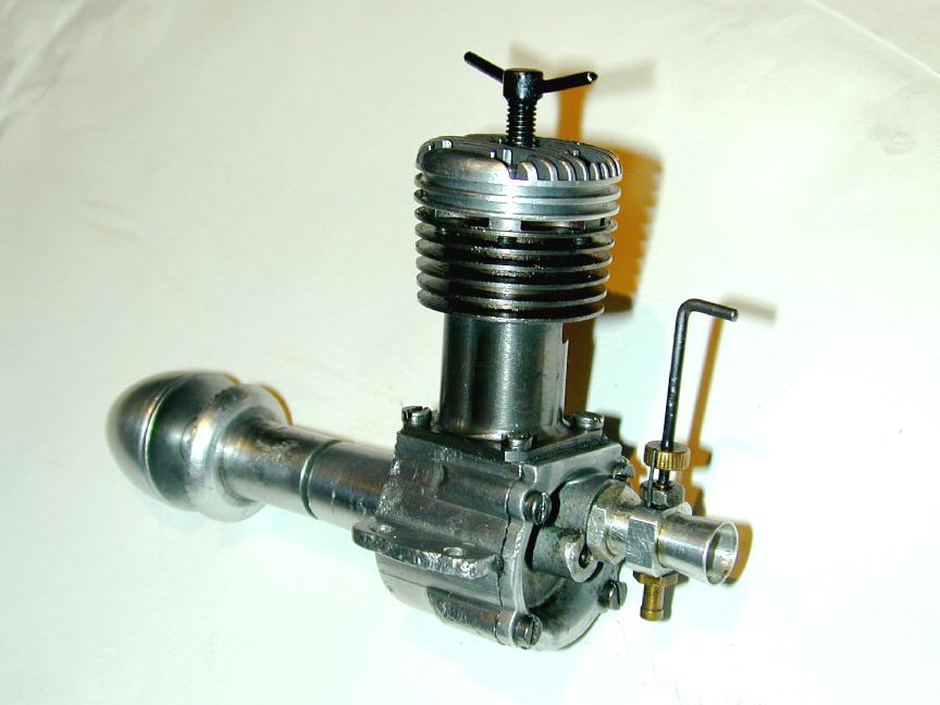
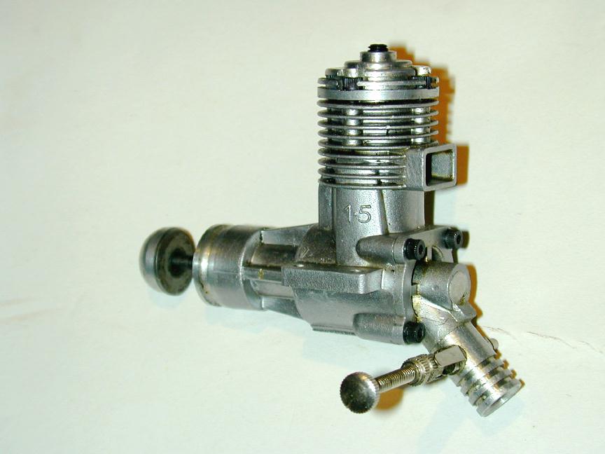
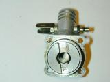
Rear Rotor Madness: The Answers?
In the November Model Engine News column, I presented some backplate and rotor assemblies for you to test your Old Motor Knowledge Quotient against. Time and Feeneys just plum ran away from me while preparing the December issue, so the answers had to be held over until now. In an effort to drag out the suspense as long as inhumanly possible, the same thumbnail pics appear below, but this time, clicking on one will present a view of the complete engine belonging to the backplate. To show just what kind of a sadist I can be, no name will appear, thus allowing me to stretch this out for another month <insert evil chuckle here>.
Photo 1
|
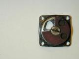
Photo 2
|
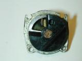
Photo 3
|
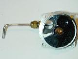
Photo 4
|
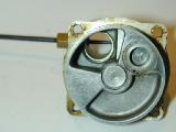
Photo 5
|
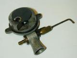
Photo 6
|
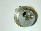
Photo 7
|
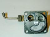
Photo 8
|
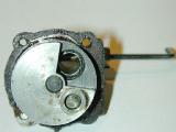
Photo 9
|
And Photo 10, the bonus point engine...
Coming Next Month
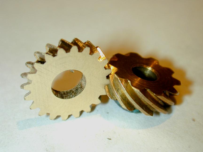
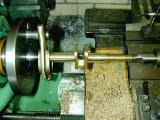
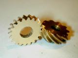 WooHoo!! It's December 30, and I'm about to post the January Model Engine News Page to the web, but thought I'd sneak in this little taste of what's to come next month. The hurdle to completing the Feeney four-stroke has been left behind—I've managed to produce the 30 degree, 40 DP, 20 tooth skew gear required for the cam shaft. The one lying down came with the kit; the one standing up, together with all the required cutters, jigs, swarf and burrs came from my shop. I bought absolutely nothing to do this—everything came from the scrap bin. Expect this to be written up during January and posted in February.
 Auction Pending: Christie's
 Editorial